Today I was able to drive a line on SRM pitch and yaw, aka SRC1 P and Y, in an attempt to understand how the SRM alignment signal appears in various sensors. Our current configuration has SRM alignment controlled via the AS RF72 signal, which is the beat of the 118 MHz and the 45 MHz.
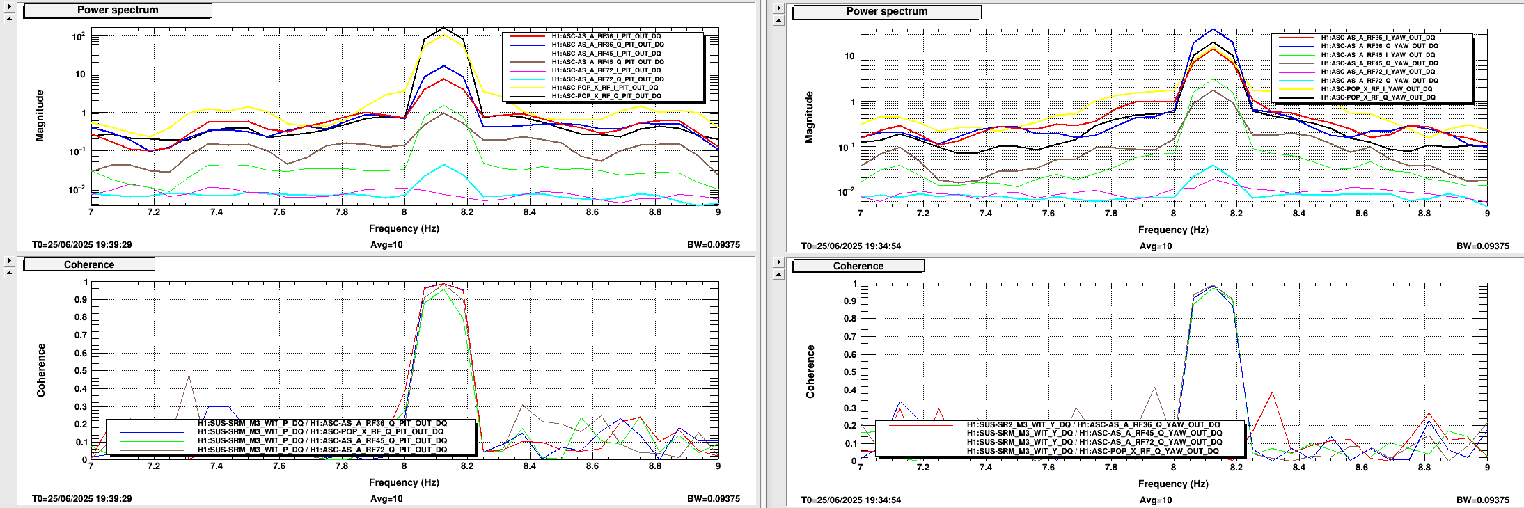
To do this measurement, I engaged the usual 8.125 Hz notches in the ASC loops, and drove at 8.125 Hz at the SRC1 SM exc point. I measured the signals in the I and Q phase on AS RF72, AS RF45, AS RF36 and POP X RF, which is a 45 MHz demod.
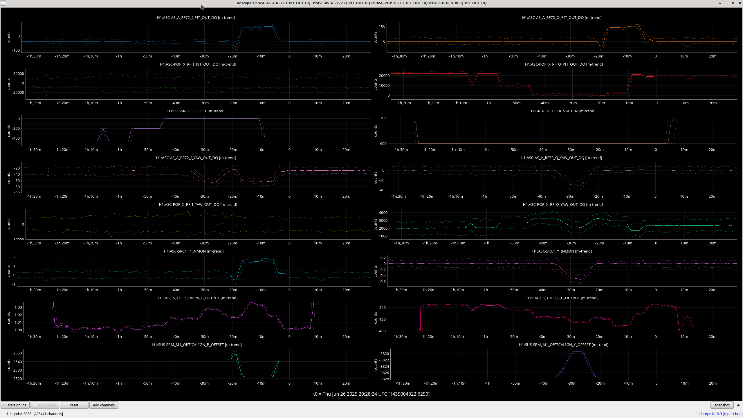
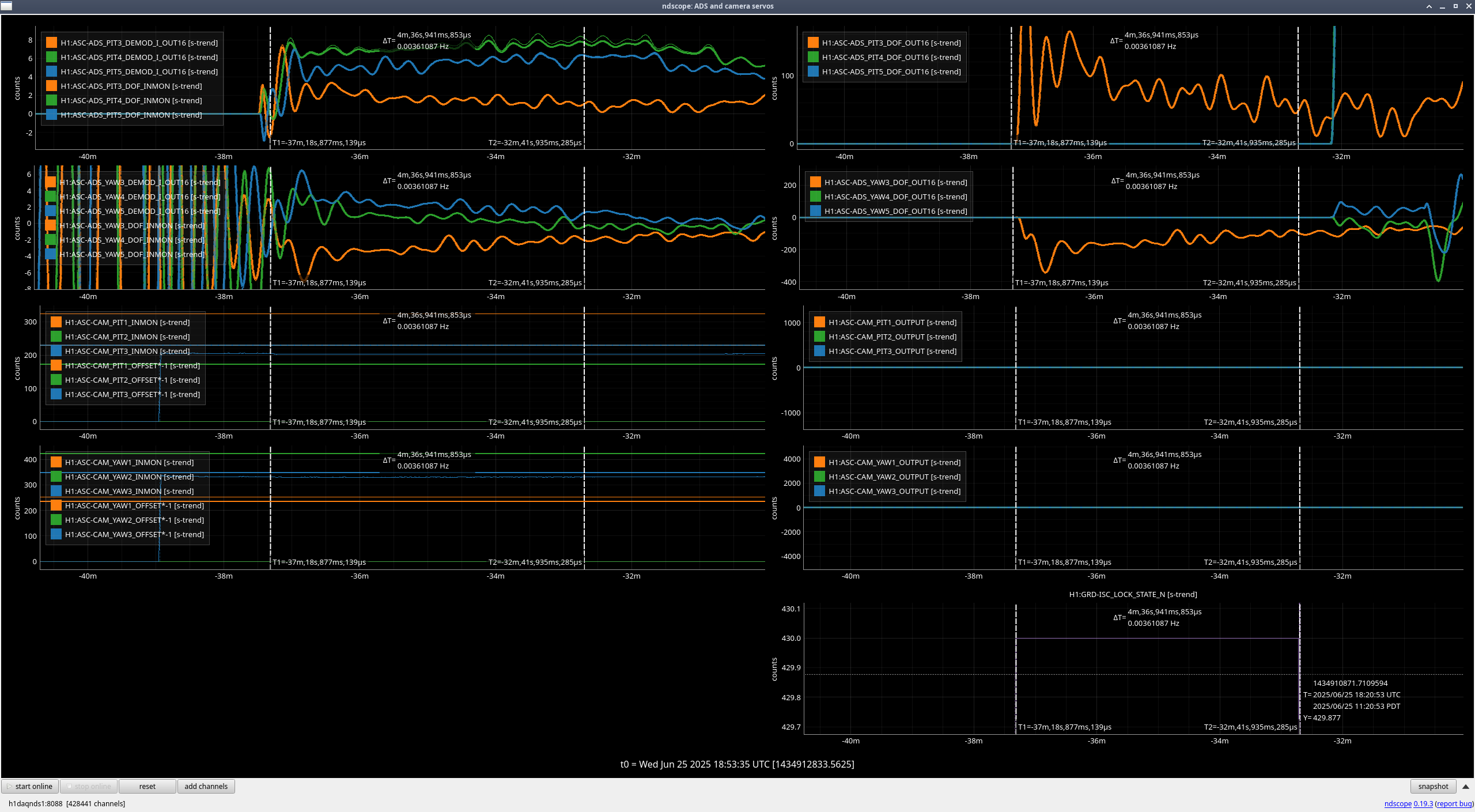
First, it is very hard to drive a large enough signal to even see the line in AS RF72 compared to other sensors. We are currently operating with 1 stage of whitening on RF72, for reference. The attachment shows how the signals appeared in the AS WFS as well as the POP WFS for pitch and yaw.
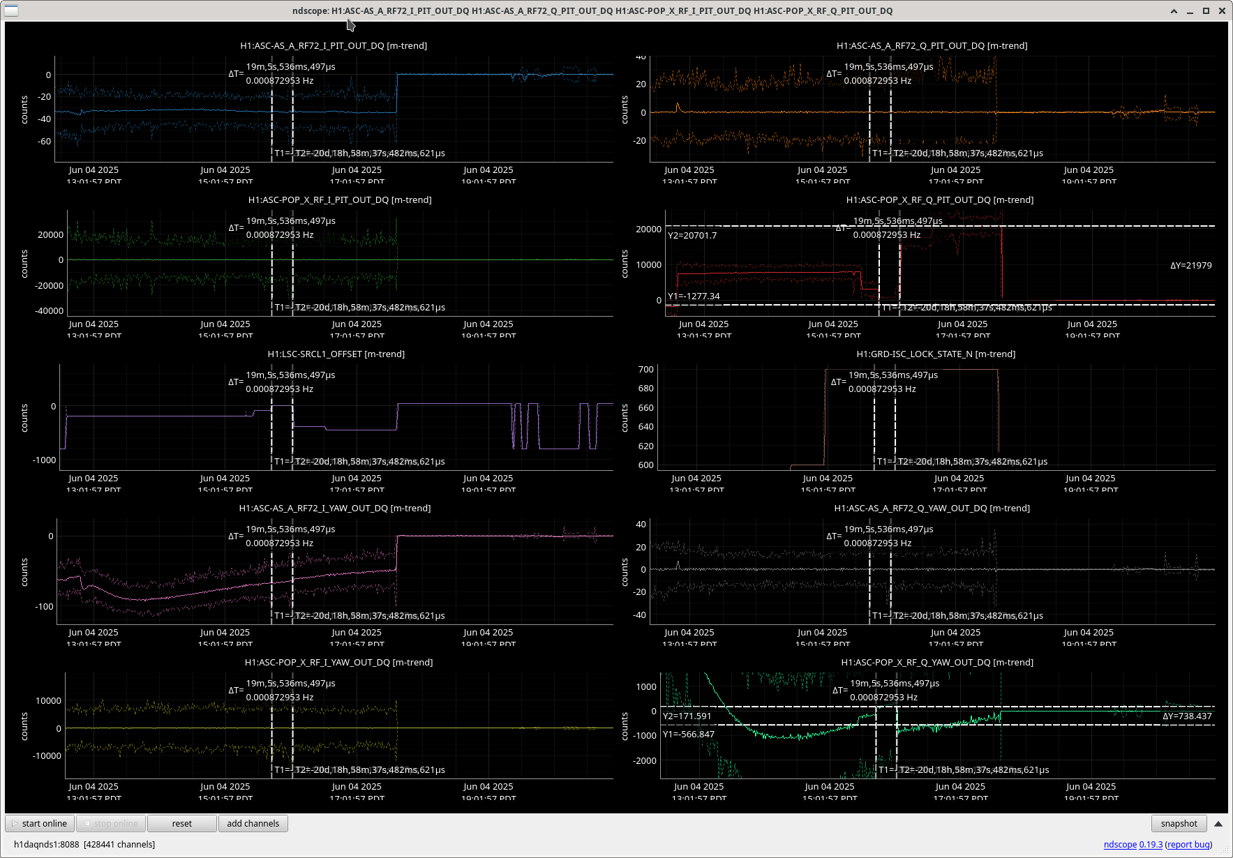
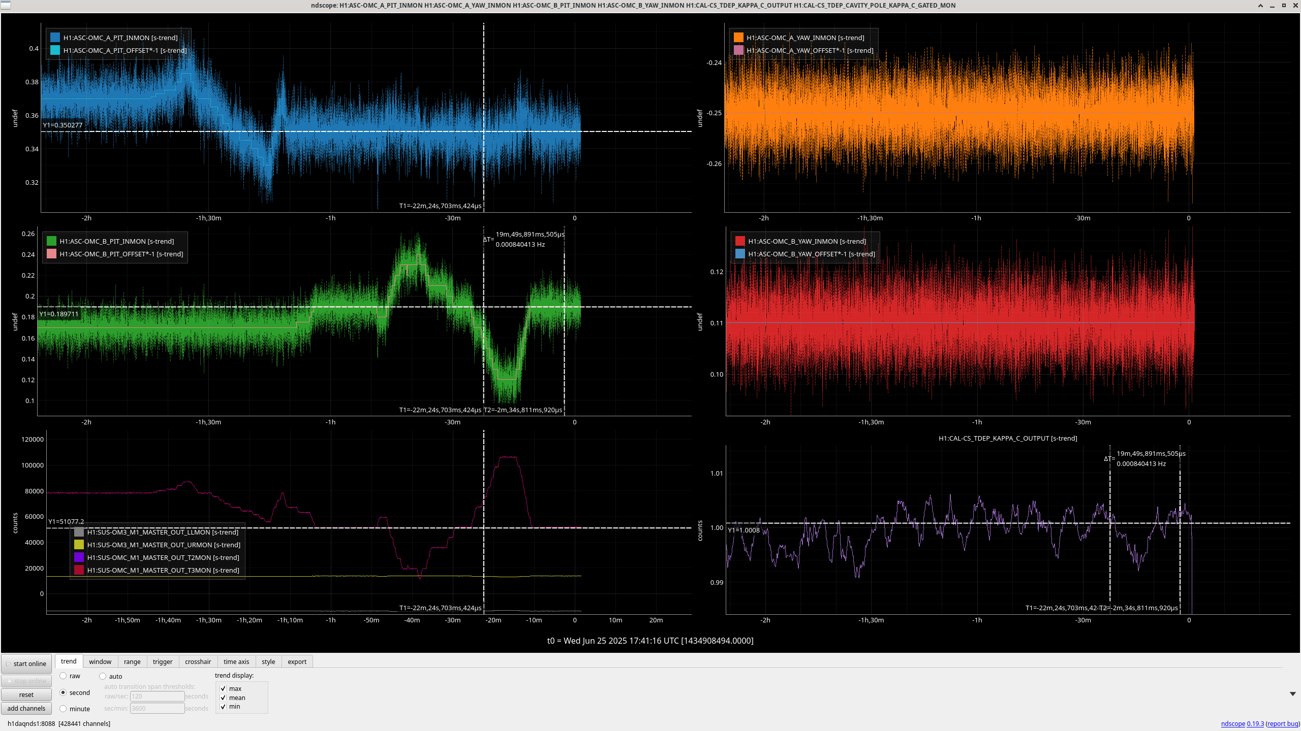
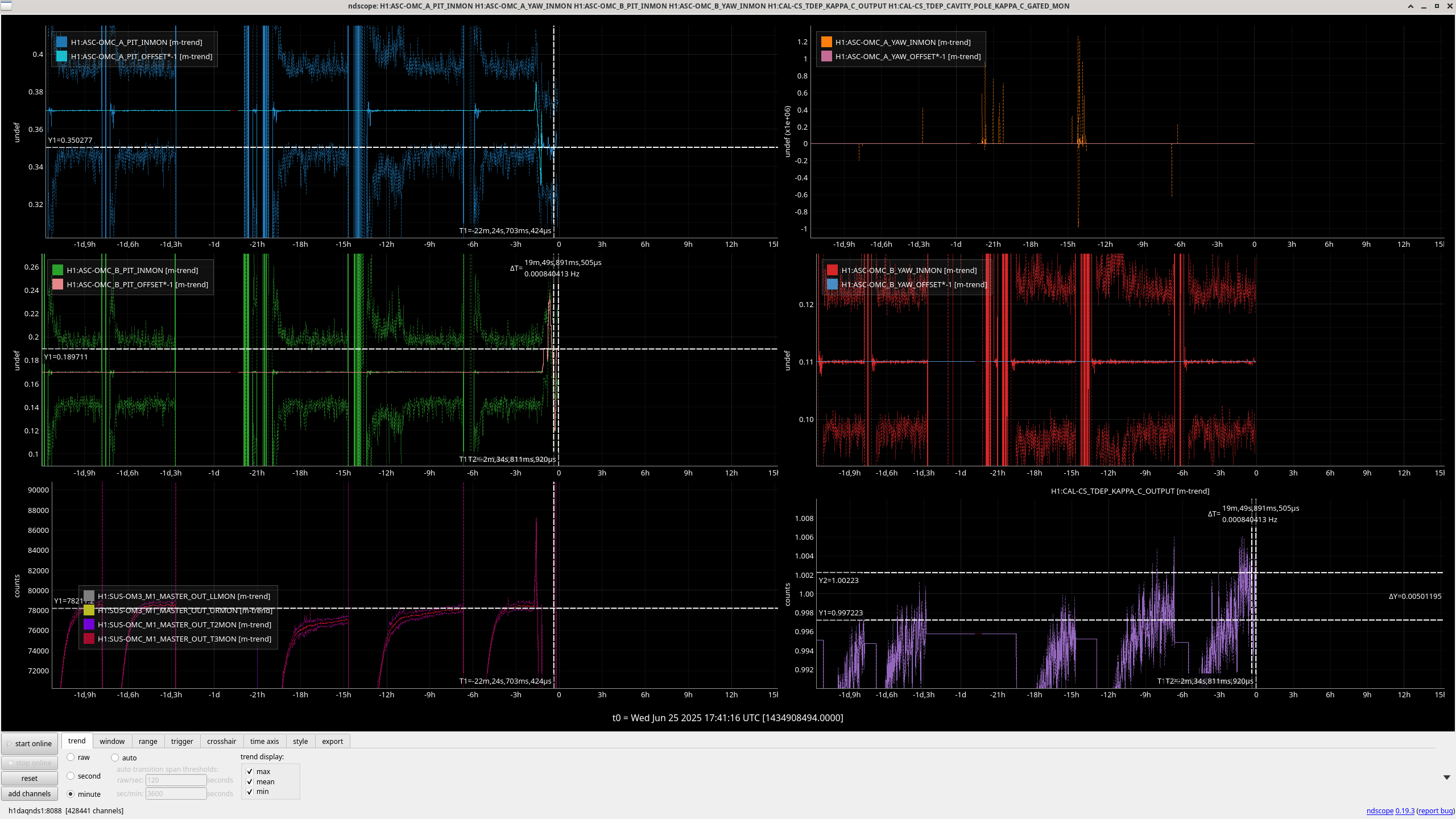
Once I took this measurement, I looked at the time series of the signals. POPX 45 Q pitch has an offset that corresponds to 1.5 urad of SRM pitch offset. I calculated this calibration factor from my injection: 7.37e-5 SRM pitch urad/POPX pit ct. The POPX Q yaw signal also had an offset, but it was much smaller, only 0.24 urad, calibration factor 3.25e-4 SRM yaw urad/ POPX yaw ct
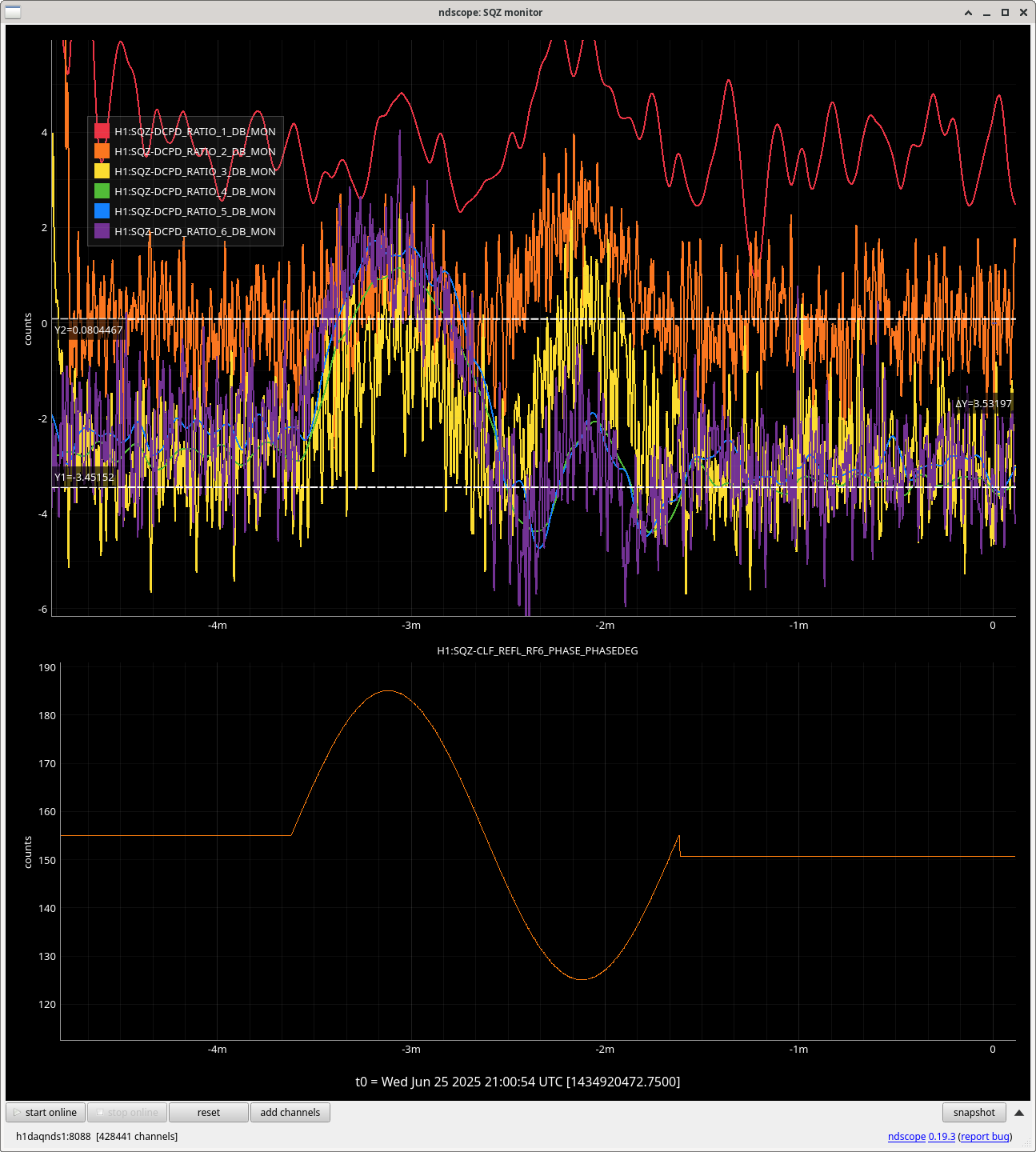
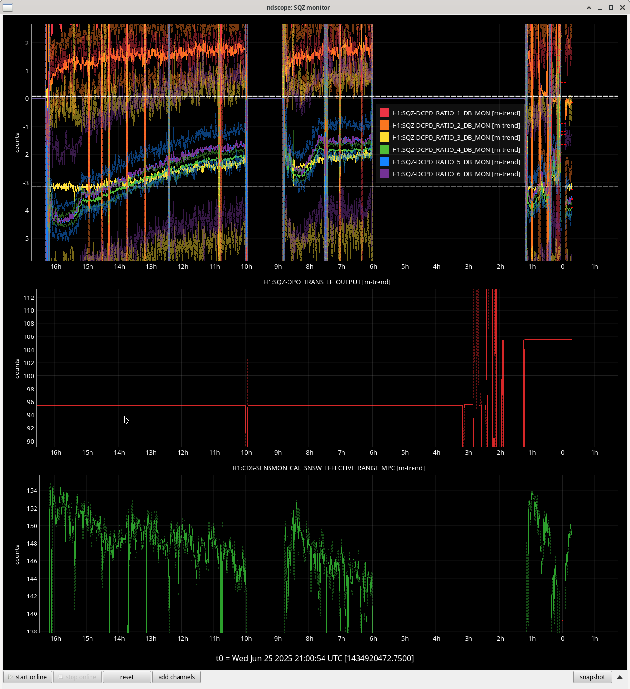
On June 5, the SQZ team adjusted the SRCL digital offset, and when the SRCL digital offset was zero, the POPX Q offsets corresponded to about 0.09 urad of SRM pitch offset and 0.05 urad of SRM yaw offset (sqz alog).
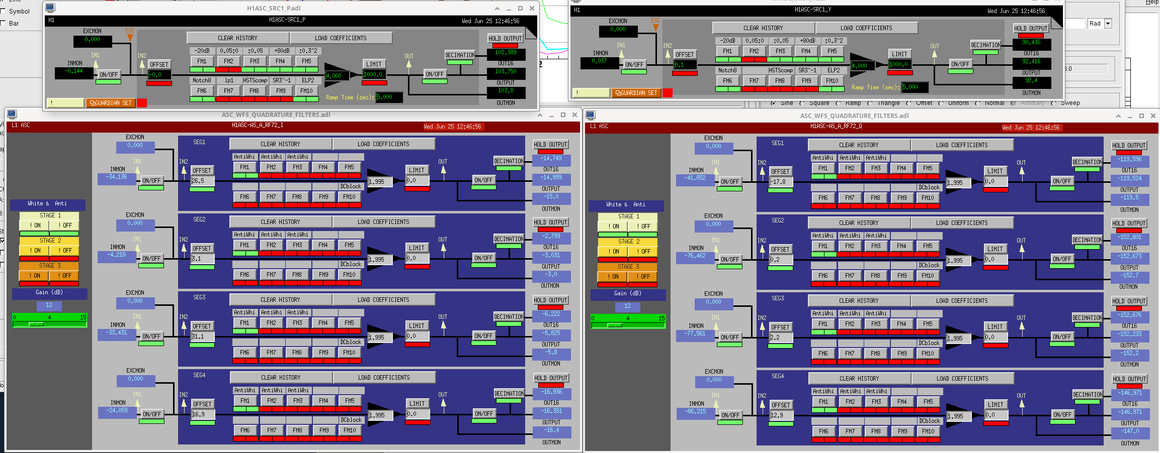
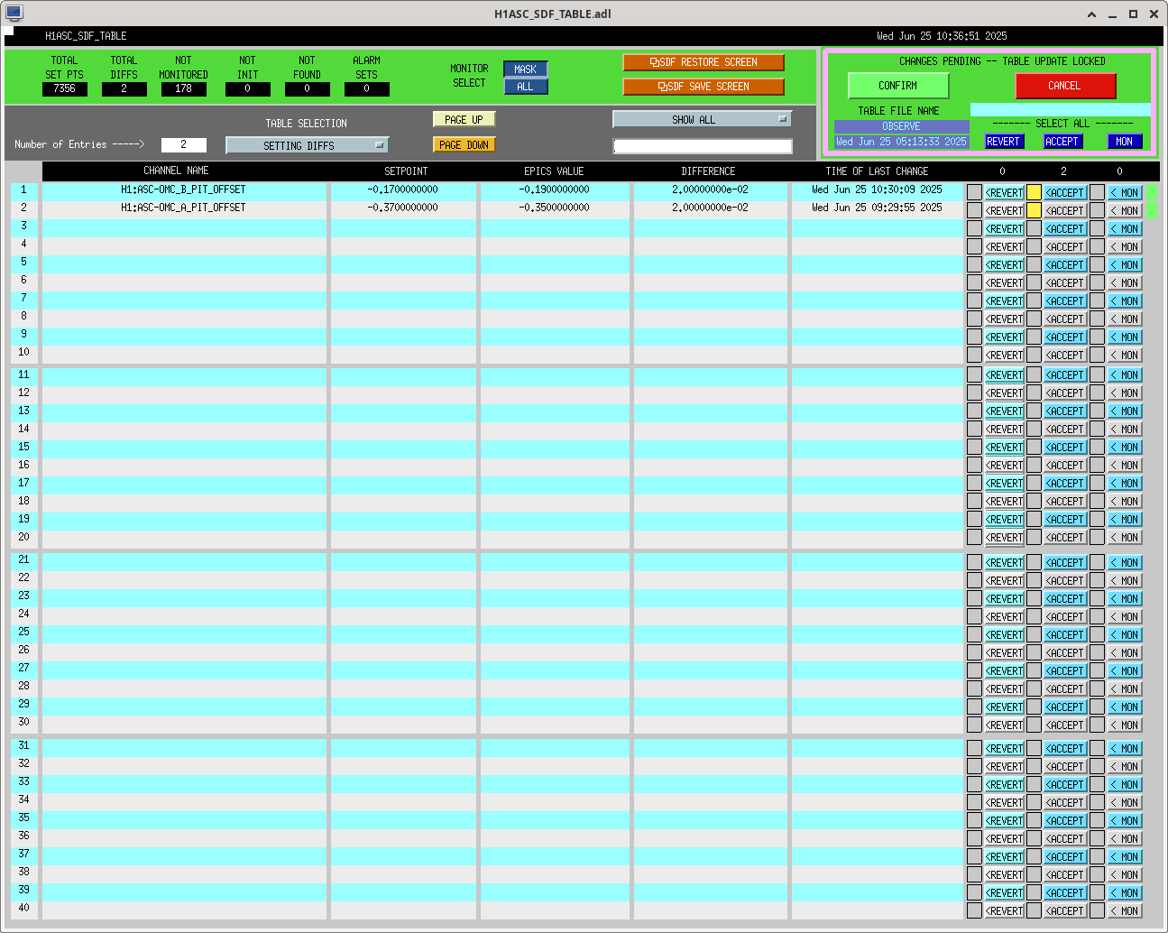
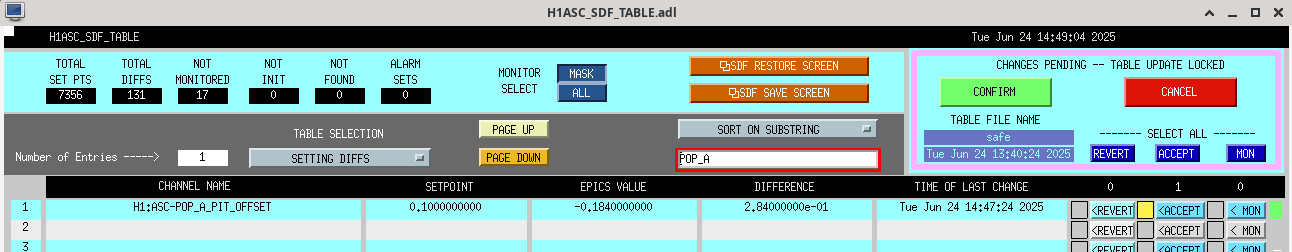
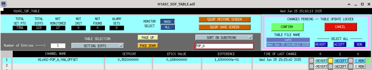
In the past, we have operated with some SRC1 offset, however, that offset is remarkably small compared to even the dark offsets we have applied to the AS RF72 channels. SRC1 p offset was set to -0.042, SRC1 Y to 0.098, while the four segment dark offsets on RF72 Q are -17.8, 0.2, 2.2, 12.9 (medm screenshot).
Overall, I think we should consider a few things:
- do we need more whitening on AS RF72?
- should we commission POPX 45 Q as the SRC1 sensor instead?
- should we adjust the alignment offsets of SRC1 to offload some of the SRCL offset?
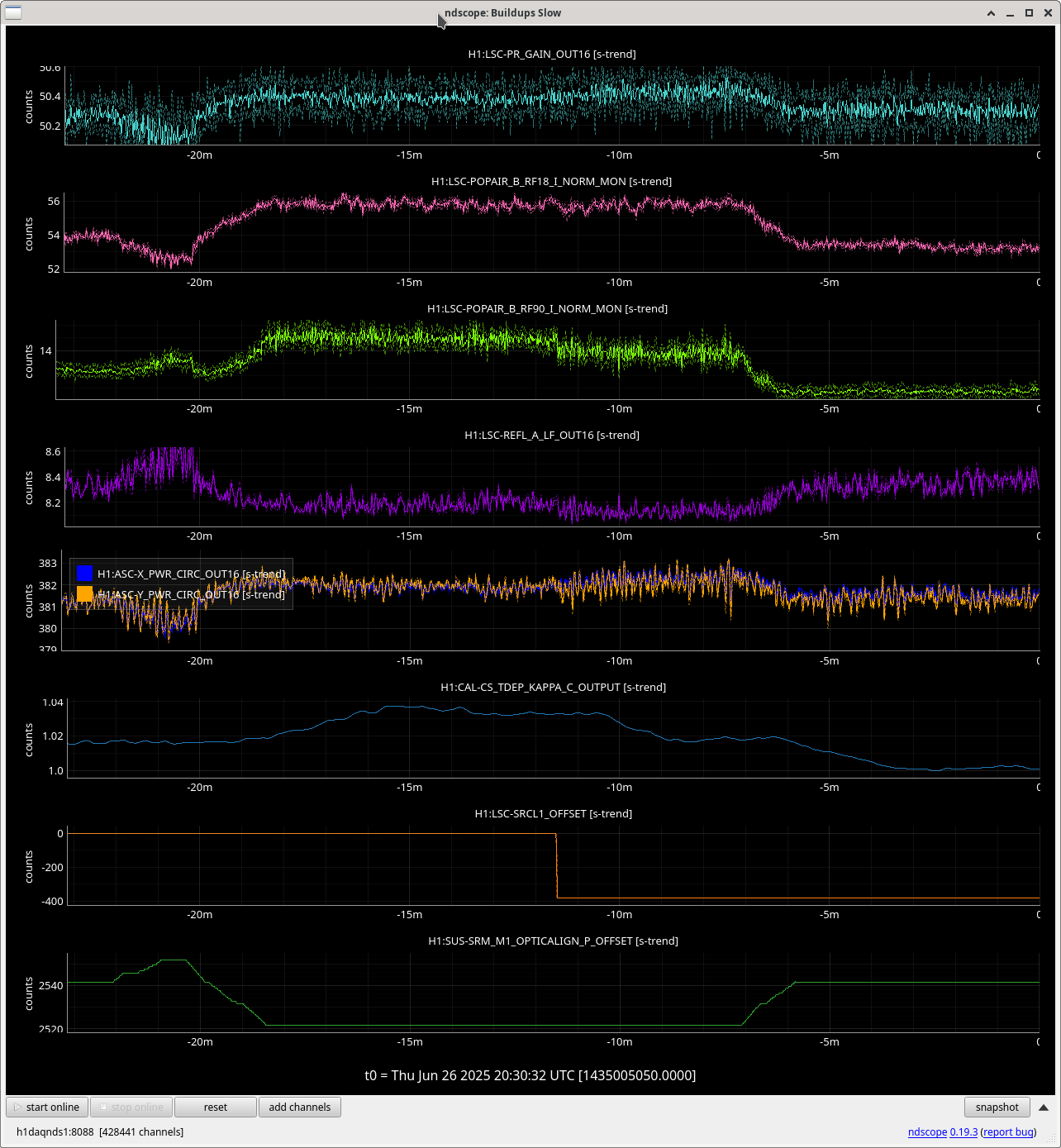
Sheila has suggested we open the SRC1 loop and try stepping the offset while monitoring the buildups, the effect of the SRCL offset on SQZ, and the overall offsets in AS RF72 and POPX Q.
Whatever effect alignment offsets in the SRC are having on the SRCL detuning seems to be much smaller in yaw than in pitch.
To calibrate the AS RF72 signals into SRM angle, we can use these factors:
0.274 SRM pit urad/ AS RF72 pit ct
0.173 SRM yaw urad/ AS RF72 yaw ct


