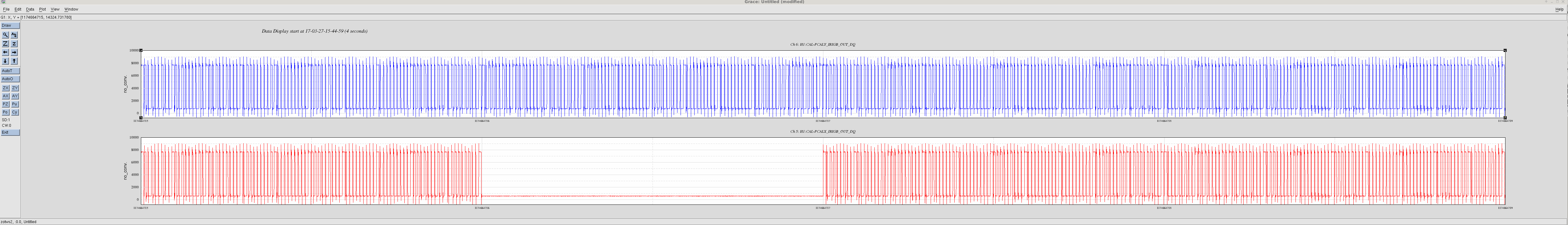
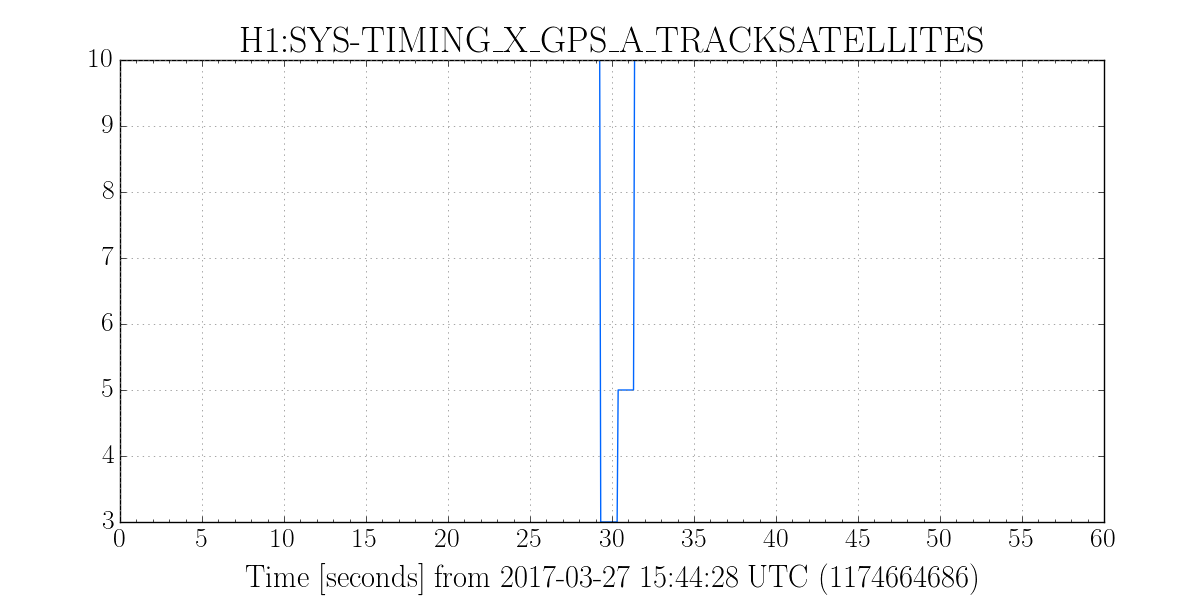
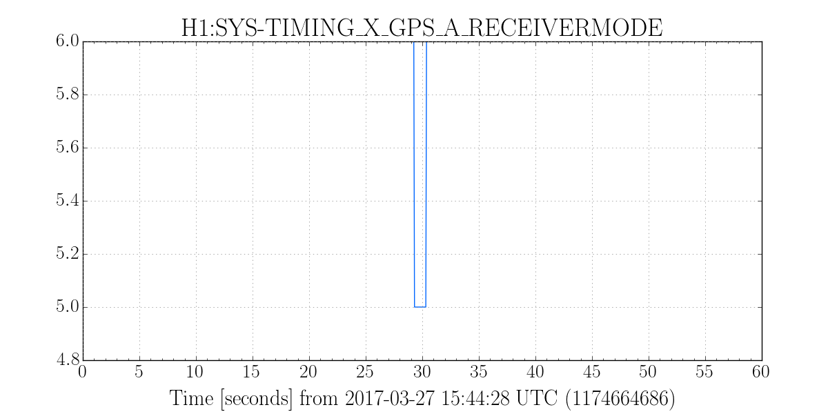
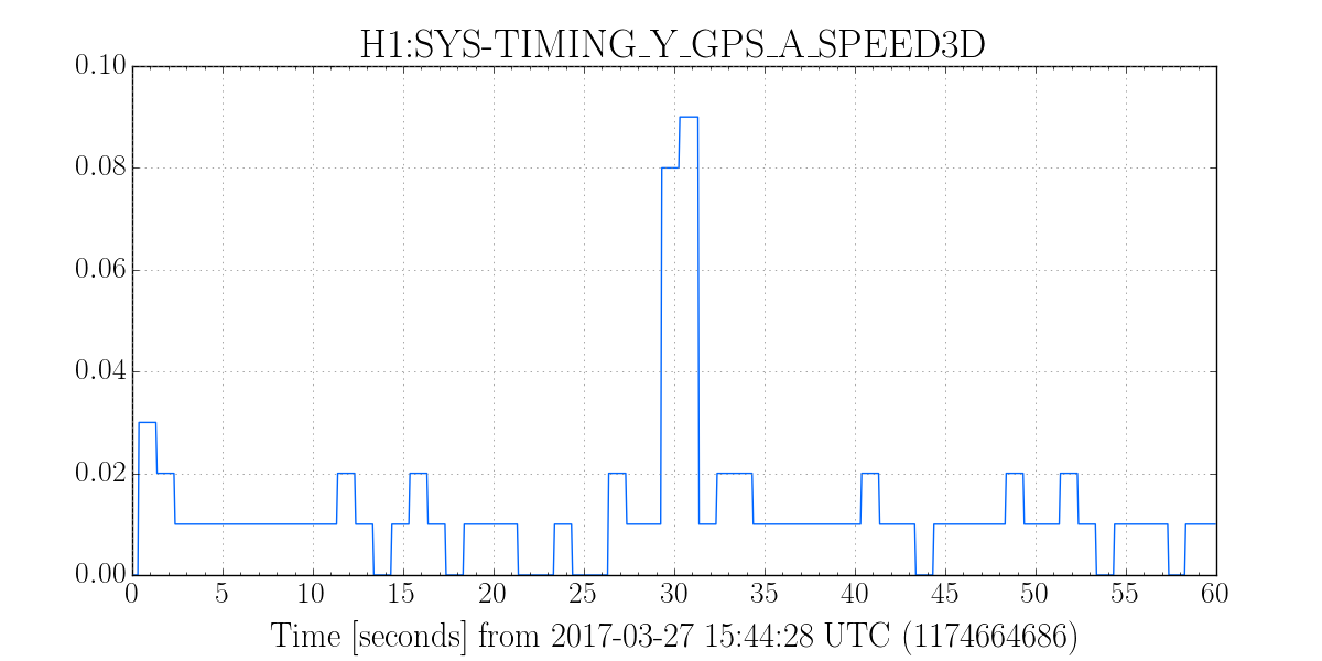
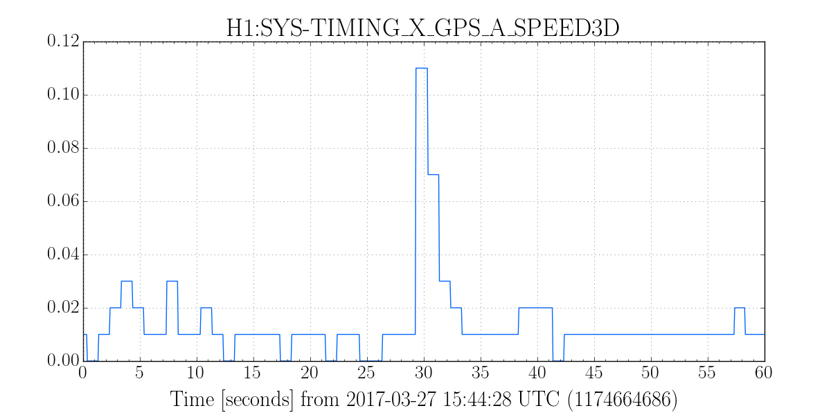
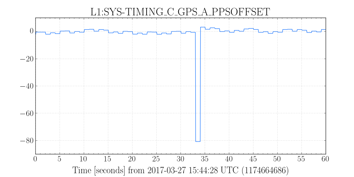
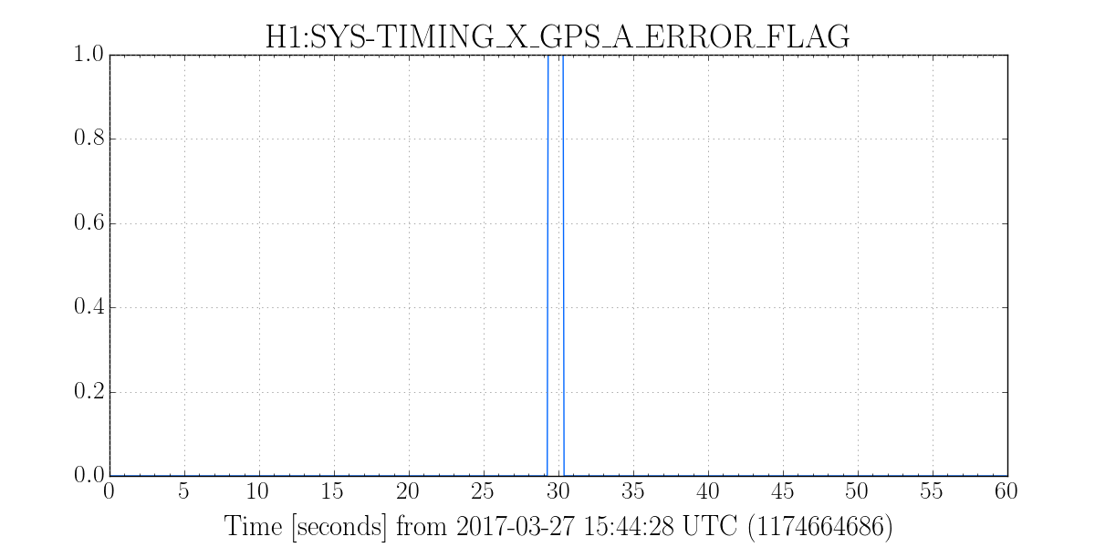
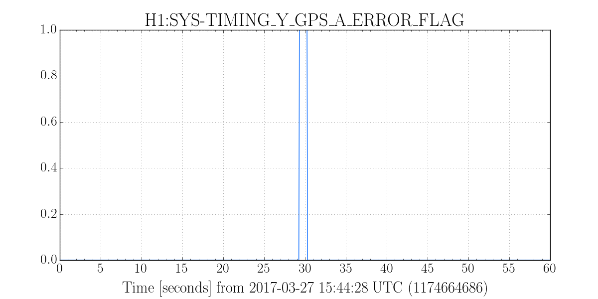
J. Kissel, K. Izumi We discovered today (see LHO aLOG 31427) that the previously most recent tag of the H1 SUS ETMY dynamical model, /ligo/svncommon/SusSVN/sus/trunk/Common/SusModelTags/Matlab/ quadmodelproduction-rev7995_ssmake4pv2eMB5f_fiber-rev3601_h1etmy-rev7915_released-2016-06-15.mat has a bug ** in which the ~1 Hz dynamics of the suspensions are junk. While exploring, we also found that the L1 SUS ETMY model tagged at the same time, /ligo/svncommon/SusSVN/sus/trunk/Common/SusModelTags/Matlab/ quadmodelproduction-rev7995_ssmake4pv2eMB5f_fiber-rev3601_l1etmy-rev7914_released-2016-06-15.mat did not include UIM-to-PUM wire violin modes. As such, I've tagged two new dynamical models, using the current damping settings at BOTH sites for ETMY (*including* optical lever damping at LHO, since we're now using Pitch damping during nominal low noise), and including upper-stage wire violin mode dynamics, /ligo/svncommon/SusSVN/sus/trunk/Common/SusModelTags/Matlab/ quadmodelproduction-rev8274_ssmake4pv2eMB5f_fiber-rev3601_h1etmy-rev7915_released-2016-11-11.mat quadmodelproduction-rev8274_ssmake4pv2eMB5f_fiber-rev3601_l1etmy-rev7914_released-2016-11-11.mat I attach plots of the transfer functions from UIM, PUM, and TST to TST in the longitudinal direction for both interferometers, comparing all ETMY-specific tags in the repo. Details ::::::::::::::::::::::: The damping loop settings for both sites were captured at the same time, while both IFOs were in nominal low noise. These filters are captured here: /ligo/svncommon/SusSVN/sus/trunk/QUAD/Common/MatlabTools/QuadModel_Production/ dampingFilters_h1etmy_20161111.mat dampingFilters_l1etmy_20161111.mat The wire violin mode frequencies are currently the same for both sites, taken from LHO aLOG 24917. There're not actually the same, but LLO hasn't measured theirs yet, so this'll have to do for now. Remember, - the calibration group has an external SVN link to this directory of model tags here: /ligo/svncommon/CalSVN/aligocalibration/trunk/Common/externals/SUSdynamModelTags/ so they don't have to download the whole SUS svn just to use these tags. I suggest the ISC group do the same, though I haven't made new tags for any of the other three QUADs in either IFO. - Models are tagged using the function /ligo/svncommon/SusSVN/sus/trunk/Common/MatlabTools/tagsusdynamicalmodel.m ** I've traced the bug back to the addition of Sus. Point to TOP Mass violin modes. If you call /ligo/svncommon/SusSVN/sus/trunk/QUAD/Common/MatlabTools/QuadModel_Production/ generate_QUAD_Model_Production.m and insist that it includes all of the QUAD's violin modes, >> quadModel = generate_QUAD_Model_Production(freq,buildType,svnDir,plotFlag,isDamped,filterFile,useModalDamping,modalDOFs,includeViolinModes,nViolinModes) where includeViolinModes = true; nViolinModes = [25 25 25 25]; then it destroys the low frequency response. But, if you don't include any Sus. Point to TOP Mass violins by setting nViolinModes = [25 25 25 0]; then the low frequency response remains intact. This is likely a problem with the numbering of connections, and the requested transfer functions are no longer picking out the right degree of freedom. I'll have Brett take a look at this. Since the Sus. Point to TOP mass wire frequencies don't get excited when the UIM or lower stages are driven, then there's no urgency to fix the bug.
I have just discovered that some hang-ups in the calibration pipeline are due to dataValid errors in many CAL and PEM channels. a partial list of the channels that have errors (dataValid code 19373) are: H1:PEM-CS_ACC_BEAMTUBE_MCTUBE_Y_DQ H1:PEM-CS_ACC_BEAMTUBE_XMAN_Y_DQ H1:PEM-CS_ACC_BEAMTUBE_YMAN_X_DQ H1:PEM-CS_ACC_BSC1_ITMY_X_DQ H1:PEM-CS_ACC_BSC1_ITMY_Y_DQ H1:PEM-CS_ACC_BSC1_ITMY_Z_DQ H1:PEM-CS_ACC_BSC2_BS_Y_DQ H1:PEM-CS_ACC_BSC3_ITMX_X_DQ H1:PEM-CS_ACC_BSC3_ITMX_Y_DQ H1:PEM-CS_ACC_EBAY_FLOOR_Z_DQ H1:PEM-CS_ACC_HAM2_PRM_Y_DQ H1:PEM-CS_ACC_HAM2_PRM_Z_DQ H1:PEM-CS_ACC_HAM3_PR2_Y_DQ H1:PEM-CS_ACC_HAM4_SR2_X_DQ H1:PEM-CS_ACC_HAM5_SRM_X_DQ H1:PEM-CS_ACC_HAM6_OMC_X_DQ H1:PEM-CS_ACC_HAM6_OMC_Z_DQ H1:PEM-CS_ACC_IOT1_IMC_X_DQ H1:PEM-CS_ACC_IOT1_IMC_Y_DQ H1:PEM-CS_ACC_IOT1_IMC_Z_DQ H1:PEM-CS_ACC_IOT2_INPUTOPTICS_Y_DQ H1:PEM-CS_ACC_ISCT1_REFL_Y_DQ H1:PEM-CS_ACC_ISCT6_OMC_X_DQ H1:PEM-CS_ACC_LVEAFLOOR_BS_X_DQ H1:PEM-CS_ACC_LVEAFLOOR_BS_Y_DQ H1:PEM-CS_ACC_LVEAFLOOR_BS_Z_DQ H1:PEM-CS_ACC_LVEAFLOOR_HAM1_Z_DQ H1:PEM-CS_ACC_LVEAFLOOR_XCRYO_Z_DQ H1:PEM-CS_ACC_LVEAFLOOR_YCRYO_Z_DQ H1:PEM-CS_ACC_OPLEV_ITMX_Y_DQ H1:PEM-CS_ACC_OPLEV_ITMY_X_DQ H1:PEM-CS_ACC_PSL_PERISCOPE_X_DQ H1:PEM-CS_ACC_PSL_TABLE1_X_DQ H1:PEM-CS_ACC_PSL_TABLE1_Y_DQ H1:PEM-CS_ACC_PSL_TABLE1_Z_DQ H1:PEM-CS_ACC_PSL_TABLE2_Z_DQ H1:PEM-CS_ACC_PSL_TABLE3_Z_DQ H1:PEM-CS_ADC_4_29_2K_OUT_DQ H1:PEM-CS_LOWFMIC_LVEA_VERTEX_DQ H1:PEM-CS_MAG_EBAY_LSCRACK_QUAD_SUM_DQ H1:PEM-CS_MAG_EBAY_LSCRACK_X_DQ H1:PEM-CS_MAG_EBAY_LSCRACK_Y_DQ H1:PEM-CS_MAG_EBAY_LSCRACK_Z_DQ H1:PEM-CS_MAG_EBAY_SUSRACK_QUAD_SUM_DQ H1:PEM-CS_MAG_EBAY_SUSRACK_X_DQ H1:PEM-CS_MAG_EBAY_SUSRACK_Y_DQ H1:PEM-CS_MAG_EBAY_SUSRACK_Z_DQ H1:PEM-CS_MAG_LVEA_INPUTOPTICS_QUAD_SUM_DQ H1:PEM-CS_MAG_LVEA_INPUTOPTICS_X_DQ H1:PEM-CS_MAG_LVEA_INPUTOPTICS_Y_DQ H1:PEM-CS_MAG_LVEA_INPUTOPTICS_Z_DQ H1:PEM-CS_MAG_LVEA_OUTPUTOPTICS_QUAD_SUM_DQ H1:PEM-CS_MAG_LVEA_OUTPUTOPTICS_X_DQ H1:PEM-CS_MAG_LVEA_OUTPUTOPTICS_Y_DQ H1:PEM-CS_MAG_LVEA_OUTPUTOPTICS_Z_DQ H1:PEM-CS_MAG_LVEA_VERTEX_QUAD_SUM_DQ H1:PEM-CS_MAG_LVEA_VERTEX_X_DQ H1:PEM-CS_MAG_LVEA_VERTEX_Y_DQ H1:PEM-CS_MAG_LVEA_VERTEX_Z_DQ H1:PEM-CS_MAINSMON_EBAY_1_DQ H1:PEM-CS_MAINSMON_EBAY_2_DQ H1:PEM-CS_MAINSMON_EBAY_3_DQ H1:PEM-CS_MAINSMON_EBAY_QUAD_SUM_DQ H1:PEM-CS_MIC_EBAY_RACKS_DQ H1:PEM-CS_MIC_LVEA_BS_DQ H1:PEM-CS_MIC_LVEA_HAM7_DQ H1:PEM-CS_MIC_LVEA_INPUTOPTICS_DQ H1:PEM-CS_MIC_LVEA_OUTPUTOPTICS_DQ H1:PEM-CS_MIC_LVEA_VERTEX_DQ H1:PEM-CS_MIC_LVEA_XMANSPOOL_DQ H1:PEM-CS_MIC_LVEA_YMANSPOOL_DQ H1:PEM-CS_MIC_PSL_CENTER_DQ H1:PEM-CS_RADIO_EBAY_NARROWBAND_1_DQ H1:PEM-CS_RADIO_EBAY_NARROWBAND_2_DQ H1:PEM-CS_RADIO_LVEA_NARROWBAND_1_DQ H1:PEM-CS_RADIO_LVEA_NARROWBAND_2_DQ H1:PEM-CS_RADIO_ROOF1_BROADBAND_DQ H1:PEM-CS_RADIO_ROOF2_BROADBAND_DQ H1:PEM-CS_RADIO_ROOF3_BROADBAND_DQ H1:PEM-CS_RADIO_ROOF4_BROADBAND_DQ H1:PEM-CS_SEIS_LVEA_VERTEX_QUAD_SUM_DQ H1:PEM-CS_SEIS_LVEA_VERTEX_X_DQ H1:PEM-CS_SEIS_LVEA_VERTEX_Y_DQ H1:PEM-CS_SEIS_LVEA_VERTEX_Z_DQ H1:PEM-CS_TEMPERATURE_BSC1_ITMY_DQ H1:PEM-CS_TEMPERATURE_BSC3_ITMX_DQ H1:PEM-CS_TILT_LVEA_VERTEX_T_DQ H1:PEM-CS_TILT_LVEA_VERTEX_X_DQ H1:PEM-CS_TILT_LVEA_VERTEX_Y_DQ H1:TCS-ITMX_CO2_ISS_IN_AC_OUT_DQ H1:TCS-ITMX_CO2_ISS_OUT_AC_OUT_DQ H1:TCS-ITMY_CO2_ISS_IN_AC_OUT_DQ H1:TCS-ITMY_CO2_ISS_OUT_AC_OUT_DQ H1:TCS-ODC_CHANNEL_OUT_DQ H1:ODC-MASTER_CHANNEL_OUT_DQ H1:CAL-CS_TDEP_REF_INVA_CLGRATIO_TST_REAL H1:CAL-CS_TDEP_REF_INVA_CLGRATIO_TST_IMAG H1:CAL-CS_TDEP_REF_CLGRATIO_CTRL_REAL H1:CAL-CS_TDEP_REF_CLGRATIO_CTRL_IMAG H1:CAL-CS_TDEP_PCALY_LINE2_REF_D_REAL H1:CAL-CS_TDEP_PCALY_LINE2_REF_D_IMAG H1:CAL-CS_TDEP_PCALY_LINE2_REF_C_NOCAVPOLE_REAL H1:CAL-CS_TDEP_PCALY_LINE2_REF_C_NOCAVPOLE_IMAG H1:CAL-CS_TDEP_PCALY_LINE2_REF_A_USUM_REAL H1:CAL-CS_TDEP_PCALY_LINE2_REF_A_USUM_IMAG H1:CAL-CS_TDEP_PCALY_LINE2_REF_A_TST_REAL H1:CAL-CS_TDEP_PCALY_LINE2_REF_A_TST_IMAG H1:CAL-CS_TDEP_ESD_LINE1_REF_C_IMAG H1:CAL-CS_TDEP_DARM_LINE1_REF_A_USUM_REAL H1:CAL-CS_TDEP_DARM_LINE1_REF_A_USUM_INV_REAL H1:CAL-CS_TDEP_DARM_LINE1_REF_A_USUM_INV_IMAG H1:CAL-CS_TDEP_DARM_LINE1_REF_A_USUM_IMAG H1:CAL-CS_TDEP_DARM_LINE1_REF_A_TST_REAL H1:CAL-CS_TDEP_DARM_LINE1_REF_A_TST_IMAG H1:CAL-CS_TDEP_DARM_LINE1_UNCERTAINTY H1:CAL-CS_TDEP_PCALY_LINE1_UNCERTAINTY H1:CAL-CS_TDEP_PCALY_LINE2_UNCERTAINTY H1:CAL-CS_TDEP_PCALY_LINE3_UNCERTAINTY H1:CAL-CS_TDEP_SUS_LINE1_UNCERTAINTY H1:CAL-CS_CARM_DELTAF_DQ H1:CAL-CS_LINE_SUM_DQ H1:CAL-DARM_CTRL_WHITEN_OUT_DBL_DQ H1:CAL-DARM_ERR_WHITEN_OUT_DBL_DQ H1:CAL-DELTAL_CTRL_DBL_DQ H1:CAL-DELTAL_CTRL_PUM_DBL_DQ H1:CAL-DELTAL_CTRL_TST_DBL_DQ H1:CAL-DELTAL_CTRL_UIM_DBL_DQ H1:CAL-DELTAL_EXTERNAL_DQ H1:CAL-DELTAL_RESIDUAL_DBL_DQ H1:CAL-INJ_ODC_CHANNEL_OUT_DQ This seems to be going on and off. The channel list above was generated from data from gps 1162941549 (November 11, 2016 23:18:52UTC = ~15:19PST). This may be related to the oaf work. at the time.
Sheila and Daniel pointed out that we could try using the uncontrolled IMC degree of freedom to mimic the WFS offset, without actually misaligning the cavity. I was able to do this for pitch, but was unsuccessful for yaw. Also, I didn't seem to affect the PZT excitation much, but I did get rid of much of the 260 Hz peak.
To DC couple the ISS, I held the output of the 2nd loop: H1:PSL-ISS_SECONDLOOP_AC_COUPLING_DRIVE hold switch on.
In the end, I have an offset in H1:IMC-DOF_4_P_OFFSET of -240. I tried offsets for the equivalent yaw from -200 to +250, and never saw a noticeable change in the ~150 Hz peak, ~350 Hz peak, or my PZT yaw excitation. The input to both DOF4's is off, no filter modules are engaged, and the filter modules have a gain of 1. These settings are accepted in SDF.
In the attached screenshot, Ref0 in green is with no offsets, but a pitch excitation on the PSL PZT from 400-450Hz. The live red trace is about half an hour after tuning the offset, so the offset still seems pretty good, although it's very slightly worse than the very best. The difference is almost imperceptible in the spectrum though, so I'm not worried about it.
The IMC WFS aren't as well centered now as they normally are, so at some point we should go in and center them. Since I have never been on the table where the WFS are, I'm not going to do this right now.
This is the output of the move monitor script. I modified a version for myself slightly such that it is looking at the OSEM witnesses, so these are different numbers than what Sheila has been reporting.
START:
SUS-MC1_M1 -77.7139982167 -1402.28670285
SUS-MC2_M1 621.824242608 -413.66036576
SUS-MC3_M1 -295.471270998 -1542.00494924
SUS-IM1_M1 182.246573766 1119.70220065
SUS-IM2_M1 606.630602164 -207.775211709
SUS-IM3_M1 1934.44031578 150.121067417
SUS-IM4_M1 -3856.74268732 -393.785840775
SUS-PR3_M1 -814.949561082 234.55559486
SUS-PR2_M1 2282.16934135 3242.24543291
SUS-PRM_M1 -1409.3910444 385.240469094
SUS-SR3_M1 -99.7398765539 587.461403381
SUS-SR2_M1 2972.21277609 317.397060269
SUS-SRM_M1 -1729.03418399 1251.99422647
SUS-ITMX_M0 344.119433308 -16.9095533593
SUS-ITMY_M0 996.548899622 83.349298391
SUS-ETMX_M0 -43.4443293476 12.7830931998
SUS-ETMY_M0 -113.192781573 -74.8803343133
SUS-BS_M1 418.802101563 -304.67337983
PIT: SUS-MC1_M1 -84.4985341486
PIT: SUS-MC2_M1 6.57551296647
PIT: SUS-MC3_M1 84.6476471949
PIT: SUS-IM1_M1 0.176299200236
PIT: SUS-IM2_M1 0.159609803854
PIT: SUS-IM3_M1 0.0532221860708
PIT: SUS-IM4_M1 -2.72033242382
PIT: SUS-PR3_M1 -0.482648507537
PIT: SUS-PR2_M1 -4.51434128357
PIT: SUS-PRM_M1 -2.14778485358
PIT: SUS-SR3_M1 -0.307467265582
PIT: SUS-SR2_M1 1.69735082572
PIT: SUS-SRM_M1 -4.77278126446
PIT: SUS-ITMX_M0 0.266663186344
PIT: SUS-ITMY_M0 0.50801149203
PIT: SUS-ETMX_M0 1.04999779019
PIT: SUS-ETMY_M0 0.445617164846
PIT: SUS-BS_M1 1.27672698516
YAW: SUS-MC1_M1 0.762530780343
YAW: SUS-MC2_M1 0.684821504178
YAW: SUS-MC3_M1 -1.60849376182
YAW: SUS-IM1_M1 -0.0294054532108
YAW: SUS-IM2_M1 0.322776681474
YAW: SUS-IM3_M1 0.103454831846
YAW: SUS-IM4_M1 1.48293048173
YAW: SUS-PR3_M1 -0.150923145111
YAW: SUS-PR2_M1 -0.0132833502485
YAW: SUS-PRM_M1 0.341160068319
YAW: SUS-SR3_M1 0.243808779206
YAW: SUS-SR2_M1 -1.30058543927
YAW: SUS-SRM_M1 0.199403791284
YAW: SUS-ITMX_M0 -0.139022372494
YAW: SUS-ITMY_M0 0.105286976283
YAW: SUS-ETMX_M0 0.201915126583
YAW: SUS-ETMY_M0 0.160323724745
YAW: SUS-BS_M1 -0.0897574699579
If this is really a better alignment for the IMC, we should move the DOF_4 offsets into the suspension biases.
There are picomotors to center the IMC WFS. This doesn't effect the length PD, so it needs to be checked on the table. It would also be interesting to know what effect re-centering has on the 260 Hz peak. I find it somewhat puzzling that a pure shift of the beam into the interferometer has such a larger effect on the acoustic peak coupling.
One possibility is that there is some clipping towards the second loop ISS array. Does moving DOF_4 beyond the -240 offset make it worse again?
Nutsinee and I moved jenne's pitch offset to the alignement slides for MC1 +MC3. MC1 moved from 1273.5 urad to 1180.4 urad, MC3 moved from -677. to -599.7
Nutsinee redid initial alingment, and we had no trouble relocking. The recycling gain at 2 Watts was just below 32 (31.8 ish) at 30 Watts input power it is 31.3
The 260 peak was high when we first locked (10^-19m/rtHz) but has been getting better over the first 15 minutes of the lock.
We haven't moved the picomotors on the IMC WFS or checked the IMC length diode.
Related logs, 31303, 31371, 31403
Jeff, Kiwamu,
We have copied the actuator function plotting script from LLO and adopted for LHO. The code seems to run fine. It resides at
/ligo/svncommon/CalSVN/aligocalibration/trunk/Runs/ER10/H1/Scripts/FullIFOActuatorTFs/actuatorCoefficients.m
The attached are the resulting pdf showing the three sets of measurements that Jeff took in the past few days. I did not do fittin yet. Below are several notes
/ligo/svncommon/CalSVN/aligocalibration/trunk/Runs/ER10/H1/params/H1params.conf
quadmodelproduction-rev7995_ssmake4pv2eMB5f_fiber-rev3601_h1etmy-rev7915_released-2016-06-15.mat
quadmodelproduction-rev7995_ssmake4pv2eMB5f_fiber-rev3601_h1etmy-rev7915_released-2016-03-01.mat
Jeff K, Darkhan T,
Modified Kiwamu's script to save the measured actuation transfer functions - which will be used to fit the actuation function parameters (currently written in Python). The results include TFs from Nov 07, 08, 10 and 12. The Nov 12 measurements were added to the previously reported three sets (see LHO alog 31433).
The script also saves the [N/ct] actuation coefficients into a separate set of *.txt files (frequency independent), this can simplify fitting a single parameter - actuation strength for each of the stages.
The clean transfer function *.txt files were uploaded to CalSVN at (files with postscript N2ct have [N/ct] gain values):
${CalSVN}/Runs/ER10/H1/Measurements/FullIFOActuatorTFs/${date}_coefs/*Actuation_measurement.txt
${CalSVN}/Runs/ER10/H1/Measurements/FullIFOActuatorTFs/${date}_coefs/*Actuation_measurement_Npct.txt
The script that generated the txt files was placed here:
${CalSVN}/Runs/ER10/H1/Scripts/FullIFOActuatorTFs/actuatorCoefficients_Npct.m
Operator task request
Now that we're at lower power, we'd like to double check what PI's actually need to be damped. We still have damping settings set up on all the modes that rang up while at 50 W, but it looks like most of them are no longer actually needed. I trended the past several days of locks and only Modes 26, 27, 28, (and maybe 3) rang up enough to engage their damping loops. We'd like to turn off the damping for the other modes and watch and make sure that they really don't need it.
To check:
1. Once you've passed DC READOUT, guardian has turned on all the usual PI gains. Write the gains down (or I've put them in the comment below) so that you can quickly put these values back in if needed.
2. Set the gains of Modes 1 - 25 (edited to now include keeping Mode 3 on) 1, 2 , 4 - 25 to zero. Do Not zero Modes 3, 26, 27, 28 as we are definitely actively damping those. Just do this directly on the main PI medm screen under the 'gain' column.
3. Watch the modes throughout the lock. The StripTool will still give the same ring up info as always and the DTT screen is a good way to keep an eye on if something is growing.
4. If a mode starts to clearly ring up, put back in the original noted gain value and damp as usual. Make a note in the log.
I've chosen not to just auto set the gains to zero already in case the operator is busy for now. Let's get a few longer locks that are more closely watched and confirm we really dont need damping on.
Mode | Gain |
2 | 5000 |
3 | -3000 |
9 | -1000 |
10 | -1000 |
17 | 1000 |
18 | -5000 |
25 | -1000 |
26 | -3000 |
27 | 5000 |
28 | 3000 |
Fil, Jim We replaced the ADC0 card, ribbon cable, and interface card in the h1oaf0 I/O chassis after the last failure of the ADC/DAC. We also moved the h1oaf0 timing fiber and SFP on the timing fanout from port 1 to port 13. (This causes an error status on the Beckhoff timing MEDM screen, which shouldn't cause problems.) After startup, we noted that the timing status on the IOP model flashed several times, this can be observed in a raw data plot of the H1:FEC-23_STATE_WORD channel for 10 minutes ending at GPS 1162946454. See attached plot. We have not seen this behaviour previously. Present status: h1oaf0 I/O chassis replaced with x1psl0 DTS I/O chassis, but using all ADC/DAC/BIO and interface cards with the exception of ADC0 and interface card, which were replaced with a set from the x1psl0 I/O chassis.
State of H1: locking well, OAF issues
Activities:
Currently:
Cheryl's idea was very clever; we now have ~1 min PI damping downtime which is no problem and have made it through several restarts without PI being a problem.
In an effort to get the h1oaf0 to run reliably, Fil and I replaced the I/O chassis with the x1psl0 chassis from the DAQ test stand, which has been the most reliable. We used the same ADC/DAC/BIO cards as were in the original h1oaf0 I/O chassis. The ADC/DAC failed within 5 minutes. Next we will try swapping ADC0 and it's interface card.
2:44pm local Filled CP3 from control room today! Took 26 min. Set LLCV to 50% open (from 20%) and monitored the two thermocouple readings on MEDM. Since it took so long I increased nominal to 21%. CP3 Dewar is scheduled for fill on Tuesday.
T240:
Averaging Mass Centering channels for 10 [sec] ...
2016-11-11 12:46:08.555164
There are 4 T240 proof masses out of range ( > 0.3 [V] )!
ETMY T240 3 DOF Z/W = 0.328 [V]
ITMX T240 1 DOF X/U = -0.47 [V]
ITMX T240 3 DOF X/U = -0.46 [V]
ITMY T240 3 DOF Z/W = -0.743 [V]
All other proof masses are within range ( < 0.3 [V] ):
ETMX T240 1 DOF X/U = 0.093 [V]
ETMX T240 1 DOF Y/V = 0.075 [V]
ETMX T240 1 DOF Z/W = 0.105 [V]
ETMX T240 2 DOF X/U = 0.088 [V]
ETMX T240 2 DOF Y/V = 0.054 [V]
ETMX T240 2 DOF Z/W = 0.111 [V]
ETMX T240 3 DOF X/U = 0.051 [V]
ETMX T240 3 DOF Y/V = 0.022 [V]
ETMX T240 3 DOF Z/W = 0.061 [V]
ETMY T240 1 DOF X/U = -0.03 [V]
ETMY T240 1 DOF Y/V = -0.014 [V]
ETMY T240 1 DOF Z/W = -0.2 [V]
ETMY T240 2 DOF X/U = 0.204 [V]
ETMY T240 2 DOF Y/V = -0.201 [V]
ETMY T240 2 DOF Z/W = 0.011 [V]
ETMY T240 3 DOF X/U = -0.221 [V]
ETMY T240 3 DOF Y/V = -0.04 [V]
ITMX T240 1 DOF Y/V = 0.237 [V]
ITMX T240 1 DOF Z/W = 0.179 [V]
ITMX T240 2 DOF X/U = 0.245 [V]
ITMX T240 2 DOF Y/V = 0.204 [V]
ITMX T240 2 DOF Z/W = 0.232 [V]
ITMX T240 3 DOF Y/V = 0.177 [V]
ITMX T240 3 DOF Z/W = 0.212 [V]
ITMY T240 1 DOF X/U = 0.135 [V]
ITMY T240 1 DOF Y/V = 0.036 [V]
ITMY T240 1 DOF Z/W = 0.036 [V]
ITMY T240 2 DOF X/U = 0.071 [V]
ITMY T240 2 DOF Y/V = 0.172 [V]
ITMY T240 2 DOF Z/W = 0.163 [V]
ITMY T240 3 DOF X/U = -0.195 [V]
ITMY T240 3 DOF Y/V = 0.171 [V]
BS T240 1 DOF X/U = 0.028 [V]
BS T240 1 DOF Y/V = 0.053 [V]
BS T240 1 DOF Z/W = 0.202 [V]
BS T240 2 DOF X/U = 0.135 [V]
BS T240 2 DOF Y/V = 0.184 [V]
BS T240 2 DOF Z/W = 0.174 [V]
BS T240 3 DOF X/U = 0.031 [V]
BS T240 3 DOF Y/V = 0.082 [V]
BS T240 3 DOF Z/W = -0.014 [V]
Assessment complete.
---------
STS:
Averaging Mass Centering channels for 10 [sec] ...
2016-11-11 12:47:53.351902
All STSs prrof masses that within healthy range (< 2.0 [V]). Great!
Here's a list of how they're doing just in case you care:
STS A DOF X/U = -0.537 [V]
STS A DOF Y/V = -0.053 [V]
STS A DOF Z/W = -0.503 [V]
STS B DOF X/U = 0.098 [V]
STS B DOF Y/V = -1.23 [V]
STS B DOF Z/W = -0.064 [V]
STS C DOF X/U = -0.0 [V]
STS C DOF Y/V = -0.0 [V]
STS C DOF Z/W = -0.0 [V]
STS EX DOF X/U = -0.21 [V]
STS EX DOF Y/V = 0.553 [V]
STS EX DOF Z/W = 0.086 [V]
STS EY DOF X/U = 0.027 [V]
STS EY DOF Y/V = 0.315 [V]
STS EY DOF Z/W = 0.298 [V]
Assessment complete.
WP 6314 Fil, Jim In an attempt to stabilize the h1oaf0 ADC/DAC issue, Fil and Jim replaced the DC power supply in the h1oaf0 I/O chassis, and reseated all ADC, DAC, BIO, and interface cards in the chassis. Start time 9:31, power up of I/O chassis at 9:55. The first attempt at starting the models resulted in ADC and DAC errors like we've seen, and the IRIG-B time going negative. The models were killed, then restarted manually to watch for issues. The models started OK on the second attempt. Note that the TCS AI chassis was powered down during this work, and was powered back up once the h1tcscs model was running. We avoided tripping the TCS laser chillers.
H1 was in NLN, but the OAF issues is pressing, so I killed the H1 lock and Jim and Fil are reseating the OAF card in hopes that this will return OAF to it previously stable running.
TITLE: 11/11 Owl Shift: 08:00-16:00 UTC (00:00-08:00 PST), all times posted in UTC
STATE of H1: Lock Acquisition
INCOMING OPERATOR: Cheryl
SHIFT SUMMARY: Locking has been very straight forward tonight, two lockloss from unknown reasons, but other than that I have been in observing. Sheila suggested that I wait at NOISE_TUNINGS for 10-15 before moving on, you can run a2l while waiting. ITMY is still swinging, but not as much as I saw last weekend.
LOG:
The other night I ran Stefan's spot move script, which tracks the alignment of all optics based on the combination of ASC control signals and sliders. Tnight I tried to imitate that move of the interferometer alignemt by moving IMs, by moving IM1 I was able to see a small improvement in recycling gain, (from about 30.7 to 30.8) but no improvement in the 260Hz jitter peak. I started trying to move IM2, but moved too quickly and broke the lock.
When I moved the IMC DOF1P offset to 120 counts this is how the other optics moved:
PIT: SUS-IM1_M1_ 0.0
We measured the REFL signals at 2W with the ISS second loop engaged and off (REF traces). The RF signals measure residual RF modulation (RAM), whereas LF measured the RIN. The REFL PD sees about a factor of 10 more light than the ISS second loop PDs when unlocked.
There seems to be a wide scatter peak at ~16.5 Hz. The 9 MHz demodulated signal shows some strange smooth excess noise below 100 Hz, whereas the 45 MHz seems to see more of the jitter peaks. The 9 MHz signal has been scaled to give the same digital and electronics gain as the 45 MHz. The transimpedance gains are very similar to start with.
The 16.5 Hz peak appears to be the same one reported about two years ago in 15223. That peak is caused by scatter of the REFL beam that is transmitted by IM4, goes out the viewport and onto IOT2R. It might be worth checking if the beam dumping on IOT2R is as good as it can be. Longer term, this beam should be dumped in vacuum, on HAM2 (this was done at LLO in the post-O1 vent).
We measured 12.9 mW with 2.0 W input, when the PRM is aligned, but the interferometer is not locked. This scales to Punlock ~ 160 mW at 25 W.
When locked and after the modulation index reduction for the 9 MHz RF, we have about Plock ~ 2.2 mW of light, which is carrier dominated.
To calibrate the REFL_LF in RIN we need to divide the signal by √ Punlock x Plock ~ 18.8 mW.
The shot noise in units of RIN is then √ 2 h ν Plock / √ Punlock x Plock = √ 2 h ν / Plock .
When we are locked at 25 W, the second loop ISS diodes are exposed to 15 mW and 16.5 mW for inner and outer, respectively.
This makes REFL_LF a better sensor for relative intensity noise measurements by about a factor of 3.
Here is a measurement of the REFL signals when locked at 25 W. The reference traces are measured with 2 W and unlocked (no second loop ISS).
The red horizontal cursor corresponds to the ISS second loop shot noise. It is well reproduced by REFL_LF between 200 Hz and 3 kHz. One striking feature is the 260 Hz periscope peak that is suppressed by the ISS near shot noise level, but shows up again much stronger in REFL_LF. This peak is most likely regenerated in the interferometer from the jitter and an rms common misalignment. The situation is a little different for the set of peaks around 4 kHz. It looks like they appear weaker in REFL_LF, as if they get regenerated but with a negative sign, so that their amplitudes subtract.