thomas.shaffer@LIGO.ORG - posted 13:23, Thursday 23 March 2017 (35046)
Thursday 1pm site meeting
Large issue with the Harmonic frequency generator. working on fixing it. Not sure if swapping of the system will fix it.
Commissioning activities are being held off until we are sure we can relock. Today's commissioning time is most likely canceled due to this problem.
Went through old maintenance activities, and added new ones to the white board.
Current items:
- Insulate BRS table
- ITMY CPS noise investigation
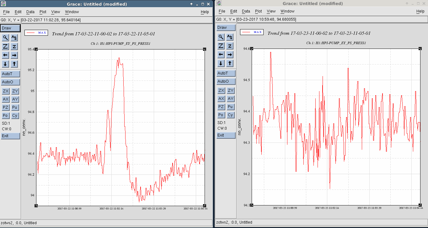
- HEPI pump controller cronjobs
- End station interlock cabling
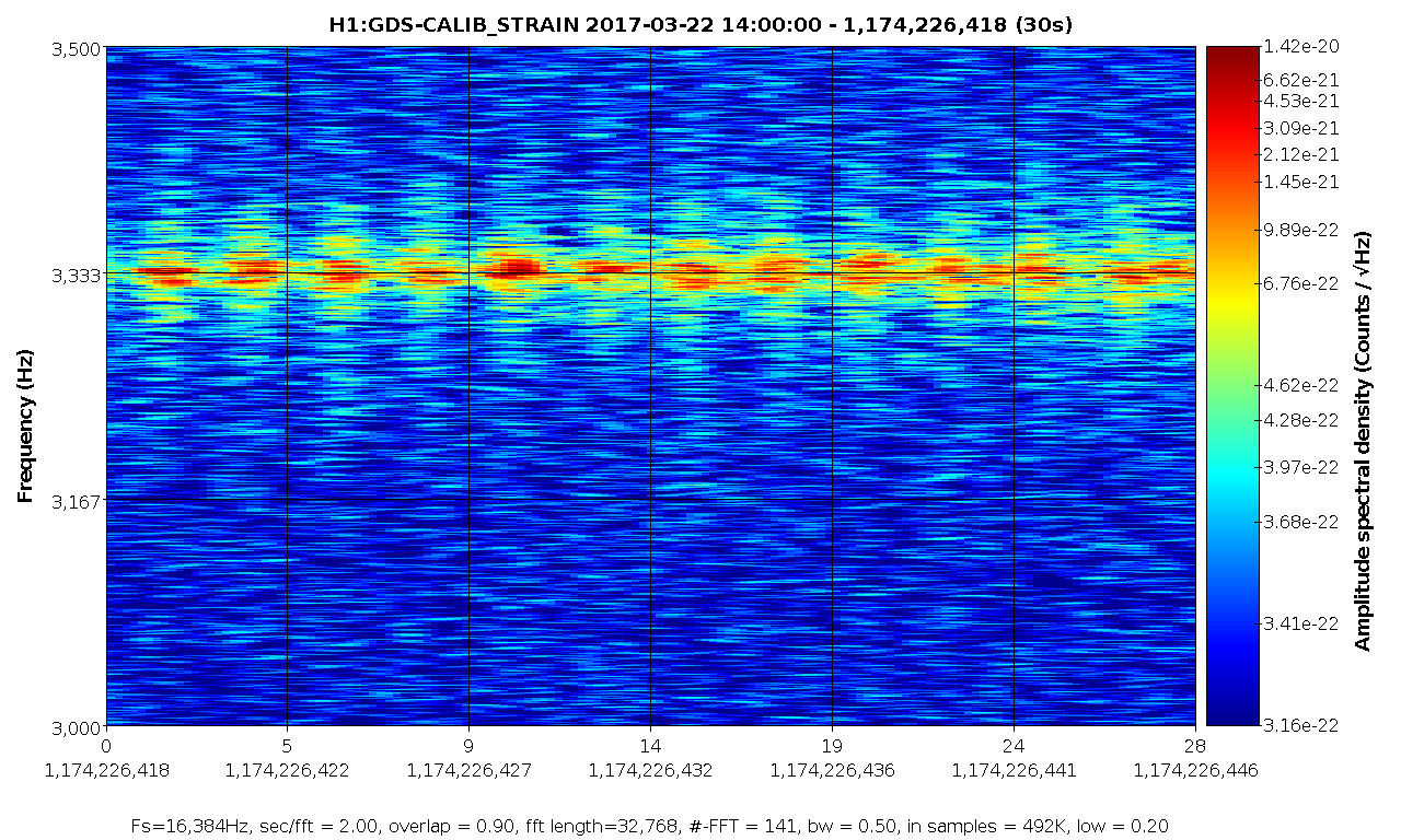
- 8hz line investigation
- Apollo water system upgrade by MX
- Apollo working at MY on Tues
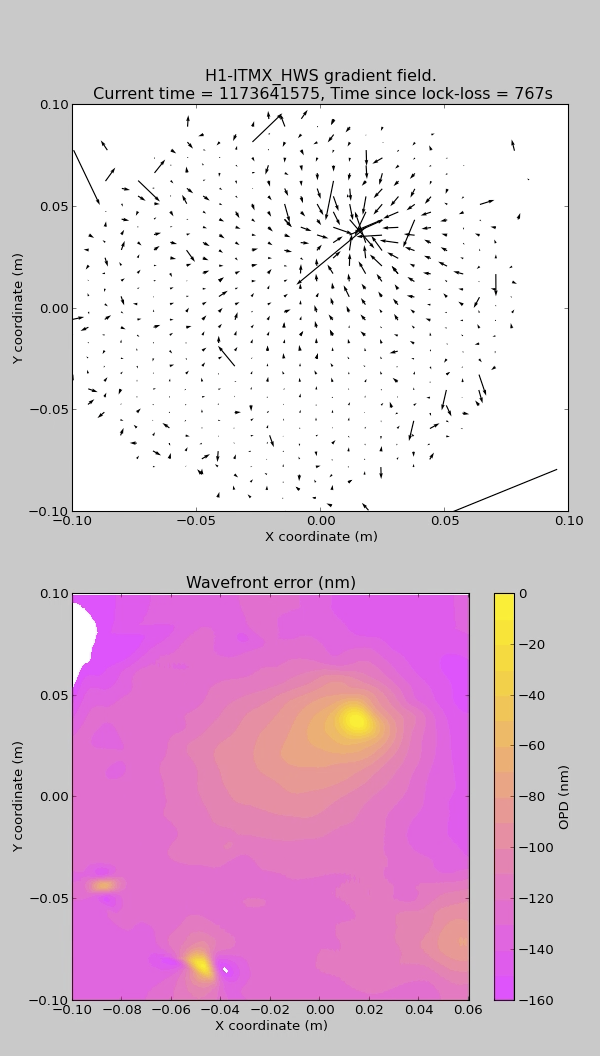
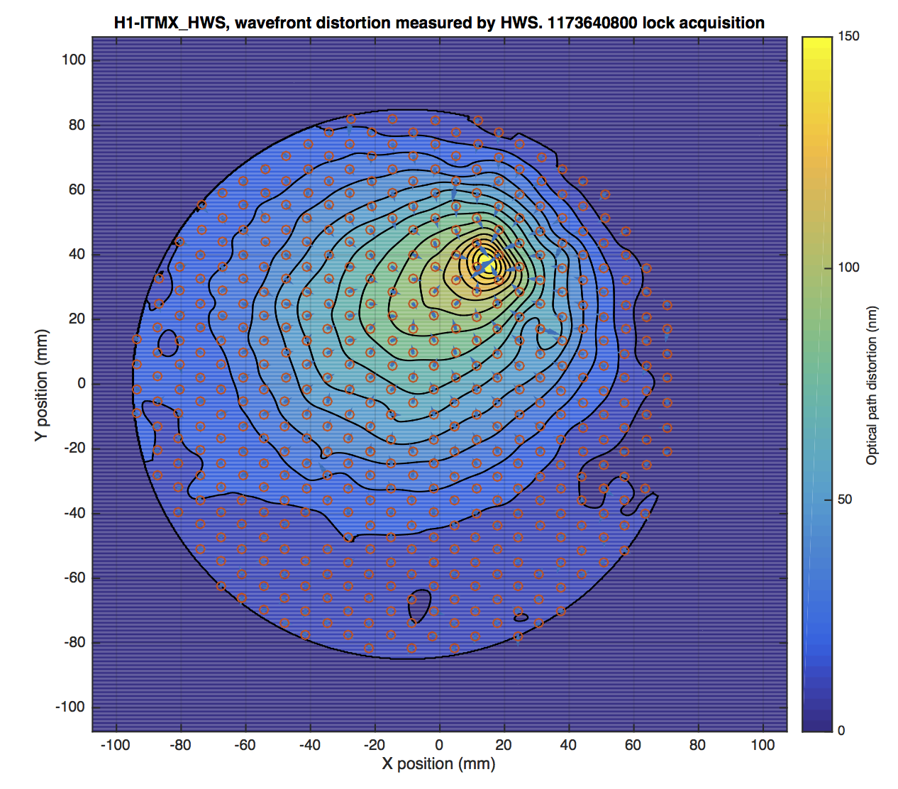
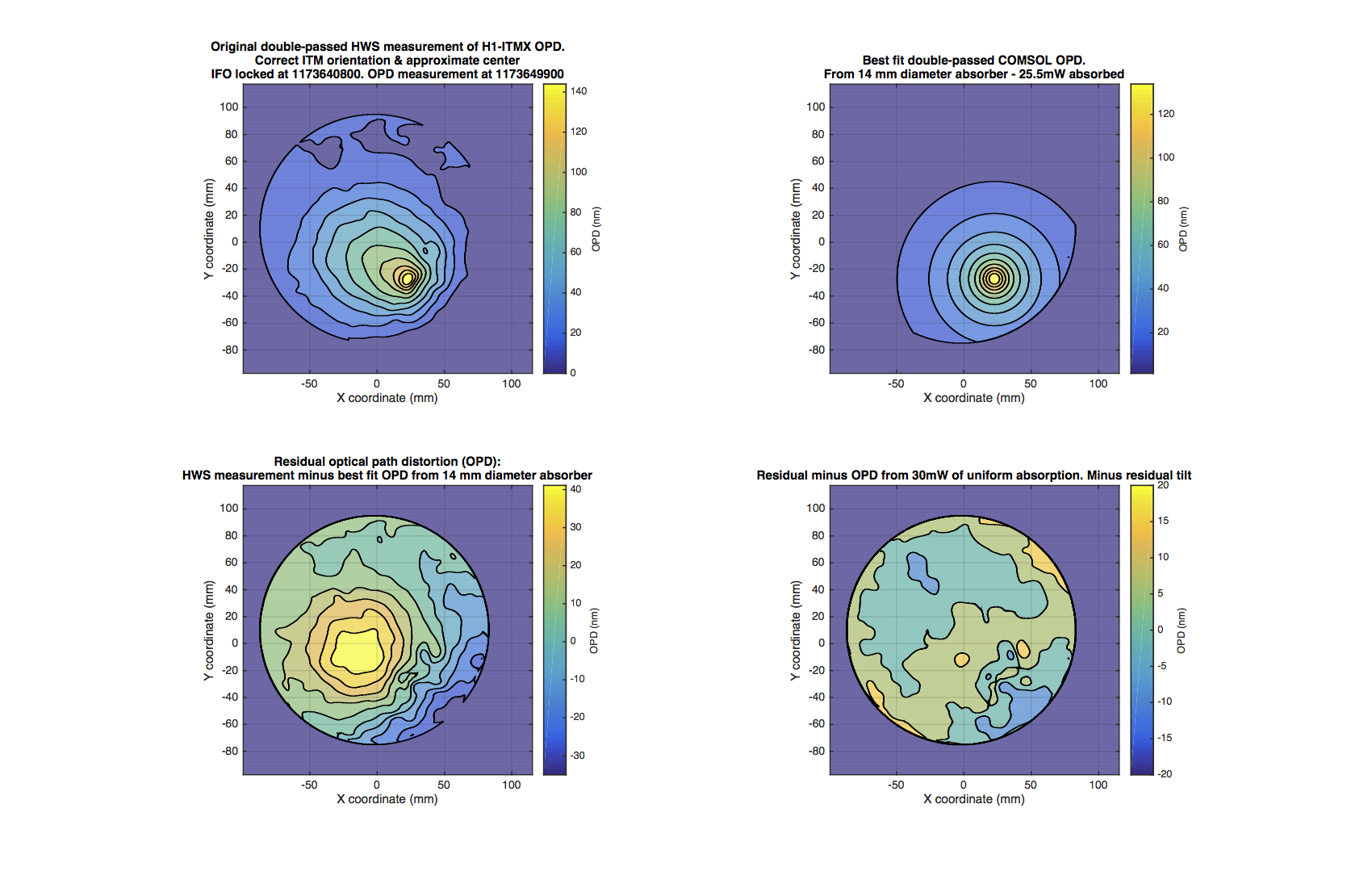
- ITMX HWS new digital camera install
- Moving magnetometers
- Take PCal camera images at EX
- Move HWS card from ES to CS
- Maintenance on the scroll/purge air compressors in the mech room of MY
- Tumbleweed baling ongoing
Went over some wanted commissioning items. Some tasks are listed on the board next to the maintenance items.
CIT property management here next week.