thomas.shaffer@LIGO.ORG - posted 14:58, Wednesday 22 March 2017 (35002)
Ops Day Shift Summary
TITLE: 03/22 Day Shift: 15:00-23:00 UTC (08:00-16:00 PST), all times posted in UTC
STATE of H1: Lock Acquisition
INCOMING OPERATOR: Ed (for 1hour)
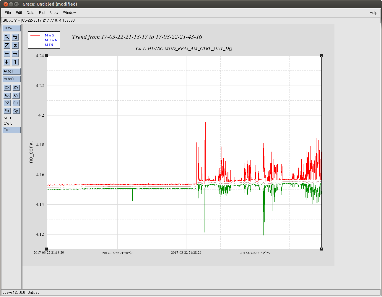
SHIFT SUMMARY: Locked this morning till commissioning at 11PST (18UTC) and at 20:30UTC we lost lock and have struggled to get it going again. Started out with the same issue I had yesterday with finding IR in ALS_DIFF. Running that state by hand very slowly seemed to work again, but not sure why that was happening. Now we are having some trouble with RF45. I'm passing off to Ed for an hour for the rest of my shift.
LOG:
- 18:06 Out od Observing for planned Commissioning.
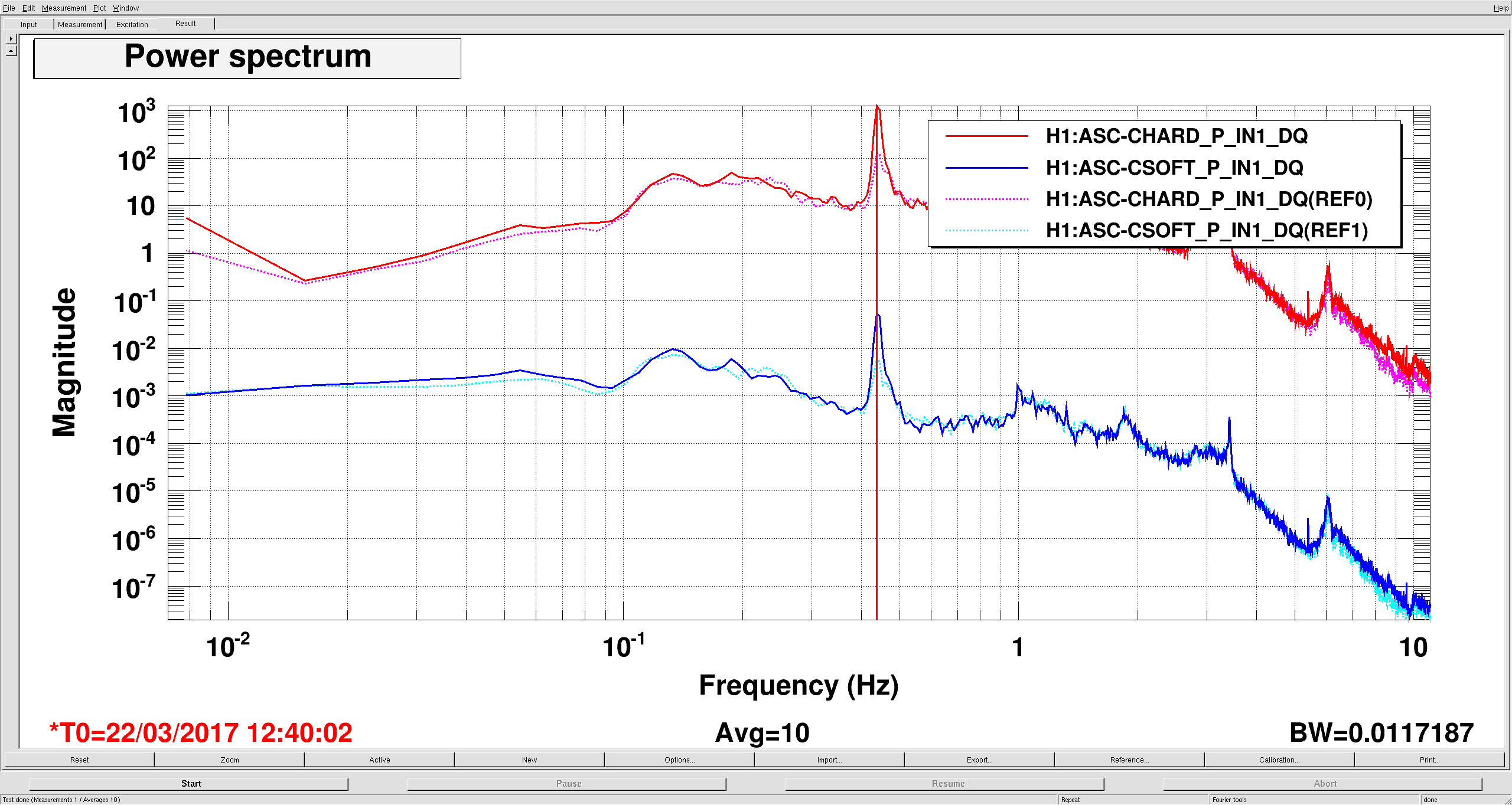
- 18:07 Running a2l
- 18:11 Robert and I opened up the rollup door by ITMX to bring in a cart., it was closed a min after.
- 18:23 Robert to LVEA
- 18:31 Suresh and Bubba to EY
- 18:34 Jonathan taking down the cdsadmin machine to diagnose the remote access issue from yesterday.
- 19:25 Suresh and Bubba back from EY
- 19:44 Richard and Fil to the vault
- 19:50 Robert out
- 21:07 Richard, Fil back
- 21:44 Richard to CER
- 21:57 Suresh, Rick, Sudarshan to EX to check temp
- 21:54 Bubba back