travis.sadecki@LIGO.ORG - posted 08:29, Saturday 18 March 2017 - last comment - 08:30, Saturday 18 March 2017(34909)
GRB alert 15:28 UTC
TITLE: 03/18 Day Shift: 15:00-23:00 UTC (08:00-16:00 PST), all times posted in UTC
STATE of H1: Observing at 67Mpc
OUTGOING OPERATOR: Ed
CURRENT ENVIRONMENT:
Wind: 10mph Gusts, 9mph 5min avg
Primary useism: 0.02 μm/s
Secondary useism: 0.25 μm/s
QUICK SUMMARY: No issues handed off. Observing for the past 7 hours.
TITLE: 03/18 Owl Shift: 07:00-15:00 UTC (00:00-08:00 PST), all times posted in UTC
STATE of H1: Observing at 68Mpc
INCOMING OPERATOR: Travis
SHIFT SUMMARY:
LOG:
12:12UTC GRB alert. Livingston contacted for confirmation of alert. Both IFOs observing.
7:20 Lockloss - ?
7:57 NLN
7:59 Checked a2l measurement - looked fine
8:00 accepted damping diffs for ITMY and ETMX as per the whiteboard notes
8:01 Intention Bit: Undisturbed 71Mpc
No alignments necessary. Had to spend time at Locking ALS to avoid repeated locklosses at FIND_IR. No further issues.
TITLE: 03/18 Owl Shift: 07:00-15:00 UTC (00:00-08:00 PST), all times posted in UTC
STATE of H1: Observing at 69Mpc
OUTGOING OPERATOR: Patrick
CURRENT ENVIRONMENT:
Wind: 4mph Gusts, 3mph 5min avg
Primary useism: 0.01 μm/s
Secondary useism: 0.26 μm/s
QUICK SUMMARY:
No news is good news
Spoke too soon.....
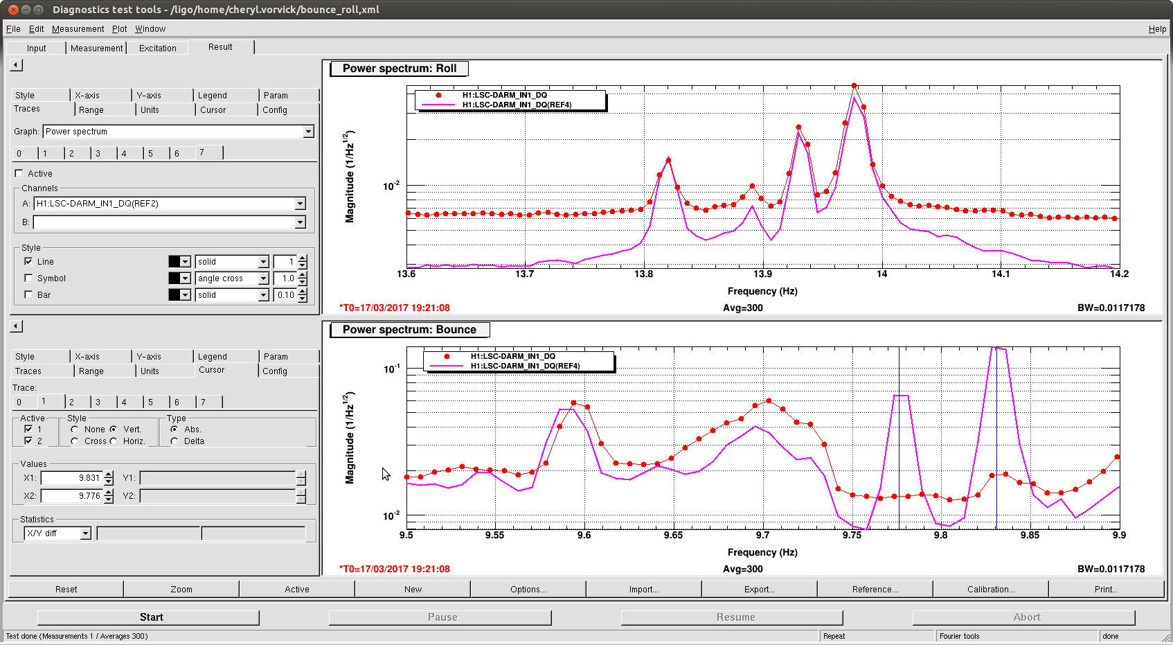
TITLE: 03/17 Eve Shift: 23:00-07:00 UTC (16:00-00:00 PST), all times posted in UTC
STATE of H1: Observing at 69Mpc
INCOMING OPERATOR: Ed
SHIFT SUMMARY: In observing the entire shift. No issues or changes in status to report. Note Cheryl's alog about SDF changes for bounce mode damping if we lose lock.
LOG:

~03:39 UTC Unidentified noise in control room. Sounded vibrational. Lasted for about a minute. HVAC?
No change in status or issues to report.
I analyzed the HWS data for the lock-acquisition that occurs around 1173641000. The "point source" lens appears very quickly (within the first 60s) and then we see a larger thermal blooming over the next few hundred seconds. I've plotted the data below (both gradient field and wavefront OPD). There are a few obviously errant spots in the HWS gradient field data. Since I'm still getting used to Python, I've not managed to successfully strip these off yet. However, it is safe to ignore them.
Check out the video too. Next step is to match a COMSOL model of thermal lensing with a point absorber to the data to get a best estimate of the size of absorber and the power absorbed (preliminary estimates are of the order of 10mW).
FYI: this measurement compares the system before, during and after a lock-acquisition (ignore the title that says "lock-loss"). The previous measurement, 34853, looked at lens decay before, during and after a lock-loss.
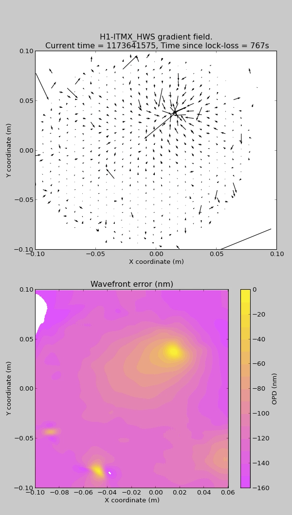
For your amusement I've attached a GIF file of the same data. My start time is 79 seconds prior to Aidan's "current time".
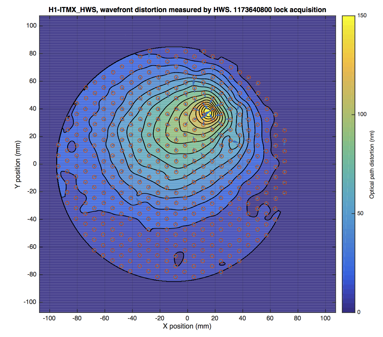
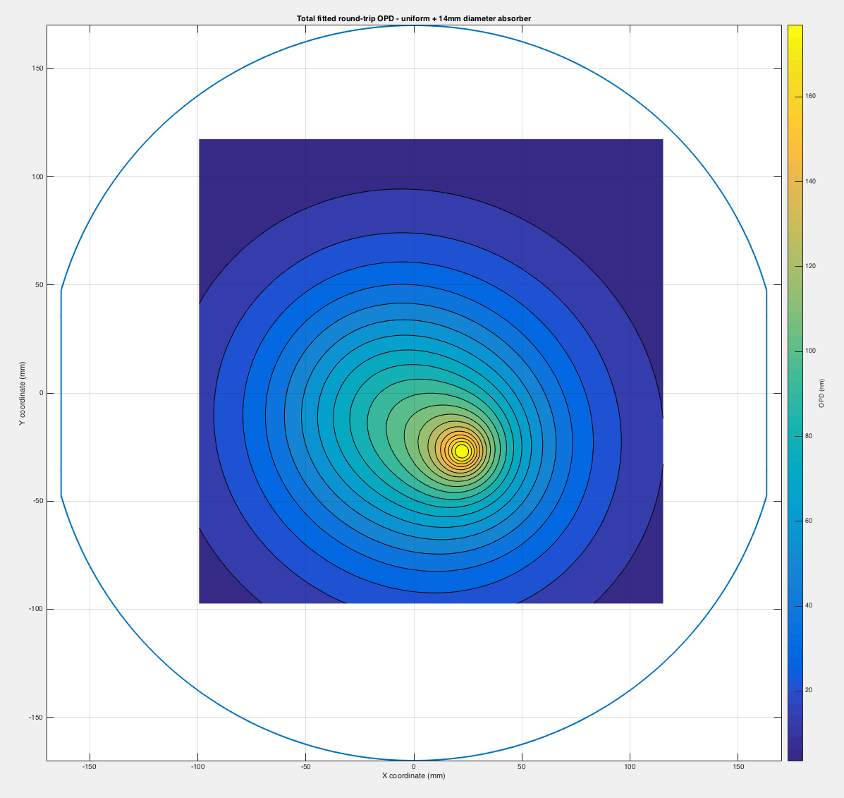
The integrated gradient field data for H1ITMX is contained in the attached MAT file. It shows the accumulated optical path distortion (OPD) after 2.75 hours following the lock acquisition around 1173640800. This is the total accumulated OPD for a round trip through the CP+ITMX substrates, reflection off ITMX_HR and back through ITMX+CP substrates.
Note: this image is inverted. In this coordinate system, the top of the ITM is at the bottom of the image.
Here is the wavefront data with the superimposed gradient field. The little feature around [+30mm, +20mm] does not appear in the animation of the wavefront or gradient field over much of the preceeding 2.75 hours. My suspicion is that this is a data point with a larger variance that the other HWS data points, rather than a true represtation of wavefront distortion.
I fitted, by eye, a COMSOL model of an absorber (14mm diameter Gaussian, ~25mW absorbed) to the measured HWS data. I then removed this modeled optical path distortion to get the following residual (lower left plot). I then fitted a COMOSL model of 30mW uniform absorption to this model and subtracted it to get the residual in the lower right plot.
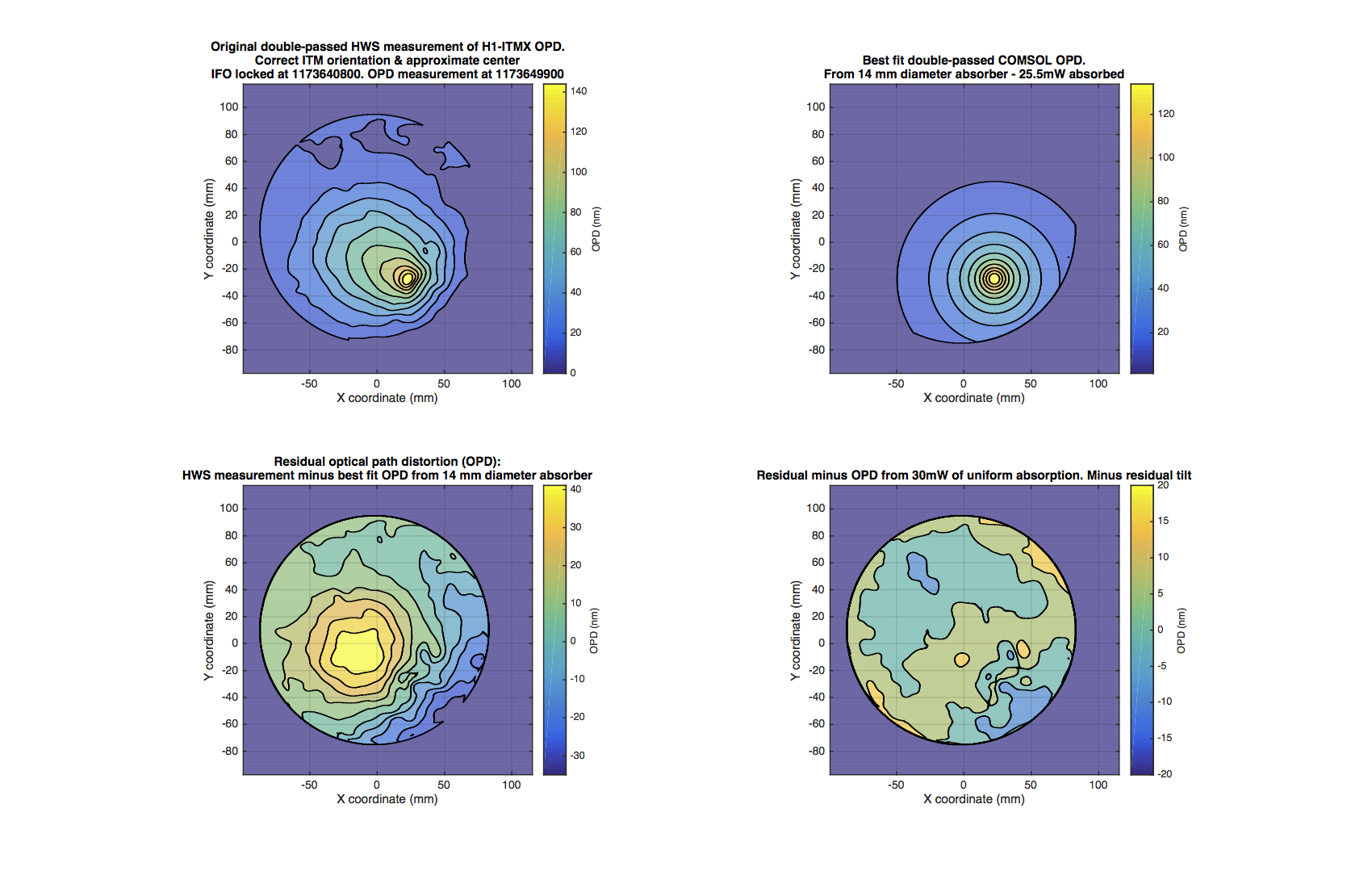
Here's the total fitted distortion from the sum of two COMSOL models (point absorber + uniform absorption):
TITLE: 03/17 Eve Shift: 23:00-07:00 UTC (16:00-00:00 PST), all times posted in UTC
STATE of H1: Observing at 69Mpc
OUTGOING OPERATOR: Cheryl
CURRENT ENVIRONMENT:
    Wind: 6mph Gusts, 4mph 5min avg
    Primary useism: 0.01 μm/s
    Secondary useism: 0.18 μm/s
QUICK SUMMARY:

No issues to report.
| ETMX | 9.776 Hz |
| ITMY | 9.831 Hz |
TITLE: 03/17 Day Shift: 15:00-23:00 UTC (08:00-16:00 PST), all times posted in UTC
STATE of H1: Observing at 66Mpc
INCOMING OPERATOR: Patrick
SHIFT SUMMARY:
This is a follow up of the jitter coupling measurements (34502, 34389).
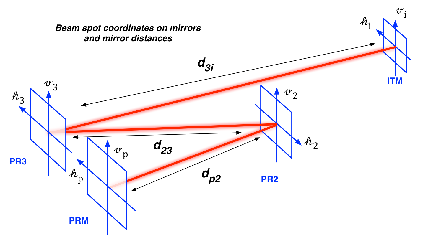
I estimated the size of the beam spot shift on the PRC mirrors (PRM, PR2, PR3 and ITMX) which we had moved during this measurement.
Here is the result for ITMX which is of our main interest (34853).
Note: if we assume a 10% calibration accuracy on the suspensions' bias sliders, the size of uncertainty is 3-5 mm.
[The script moves not only the PR3 spot but also all the spots in PRC]
As it turned out, the script that we used was actually moving not only the PR3 spot but also all other PRC mirrors despite the name of the script, pr3spotmove. Historically this script was developed in order to move the degree of freedom that is sensed by POP A QPD (28764). Indeed this script touches IM4, for example, which no doubt moves the spot on PR2.
[The move]
The way this script works is such that as we manually move PRM in angle, the script subsequently moves other optics in a deterministic manner in such way that it results in a change in POP A QPD without disturbing any of the angular control loops. Therefore, for estimating the spot positions, the quantity we need to know is the size of alignment shifts that we introduced on PRM only. This will automatically give us the alignment shifts for the other optics.
Looking at the measurement from the 1st of this month (34502), I found that we have moved PRM by -51 urad in pitch and by -36 urad in yaw. The below is a summary table of the move.
|
|
size of the move |
| PRM PIT | -51 urad |
| YAW | -36 urad |
| PR2 PIT | 0 |
| YAW | 0 |
| PR3 PIT | 0.27 urad |
| YAW | -0.09 urad |
| ITMX PIT | -1.74 urad |
| YAW | -1.04 urad |
As shown above, the script didn't touch PR2 at all. In addition to the optics listed above, the script also moved IM4, ITMY, ETMX, ETMY, SR2 and SRM at the same time. While some of them can give the same information about the ITMX spot position shift in a redundant way, I have just used the optics shown in the table to simplify the estimation of the spot positions.
[Estimation of the spot positions]
I have made an ABCDEF matrix model (e.g. LLO 9278) for the power recycling cavity with the BS and ITMY omitted. I have used the parameters that Stefan posted at 28747. By plugging the alignment vectors shown in the table, I get the following results.
[v_p, v_2, v_3, v_i] = [-0.27 mm, 016 mm, 1.7 mm, 1.7 mm]
[h_p, h_2, h_3, h_i] = [-0.43 mm, 1.7 mm, -15 mm, -15 mm]
where v and h are vertical and horizontal positions as illustrated in the cartoon below.
Also, since I wasn't sure if the calibration of suspensions' bias sliders are accurate, I assumed a 10% error in each optic and propagated them through the same ABCDEF model to estimate the uncertainties. The uncertainties are estimated to be
[delta v_p, delta v_2, delta v_3, delta v_i ] = [0.22 mm, 0.62 mm, 5.4 mm, 5.3 mm ]
[delta h_p, delta h_2, delta h_3, delta h_i] = [0.14 mm, 0.41 mm, 3.6 mm, 3.5 mm]
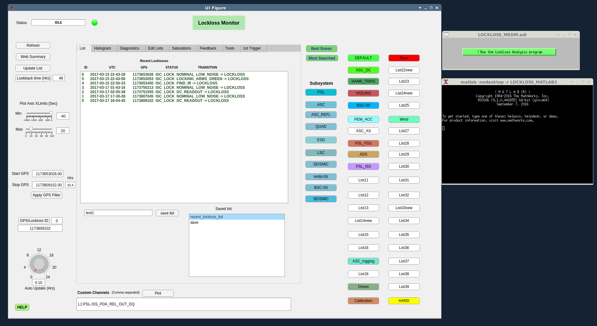
To run the new matlab lockloss application please do the following:
From the SITEMAP MEDM, Select the 'SYS' pull down, select the last item 'Lock Loss'. This opens the LOCKLOSS_MEDM.adl screen.
Press the 'Run the LockLoss Analysis program' button to start the application. An xterm should open, followed by the matlab2016b splash screen. The UI Figure graphical user interface window will then appear, and you should see no errors in the xterm window (see figure).
We have several minor issues we are working on:
To exit the program, it is best to press the 'X' close button on the top bar of both the UI and the xterm. When the UI window is closed, the matlab session won't return a command line prompt in the xterm without a ctrl-c.
The new lockloss3 python script opens an xterm which shows an error "execvp guardlog: No such file or directory" and does not show the guardlog, but the data plot is generated correctly. Also the xterm requires two 'X' close button presses to dismiss it.
Please email me if there are any other issues with this install. Thanks, Dave
we had a very brief power glitch at 20:09 UTC (13:09 PDT). It is visible on MAINS_MON trends of all 3 phases in the corner station, and also seen at the end stations (plots attached). Both GC and CDS UPS system reported the event, and the CUR fire panel beeped for about 10 seconds. Many people saw their room lights flicker.
We cannot see any issues with CDS computing, looks like we rode through OK. Jim and I checked the TCS chillers on the MR-mezanine, no problems.
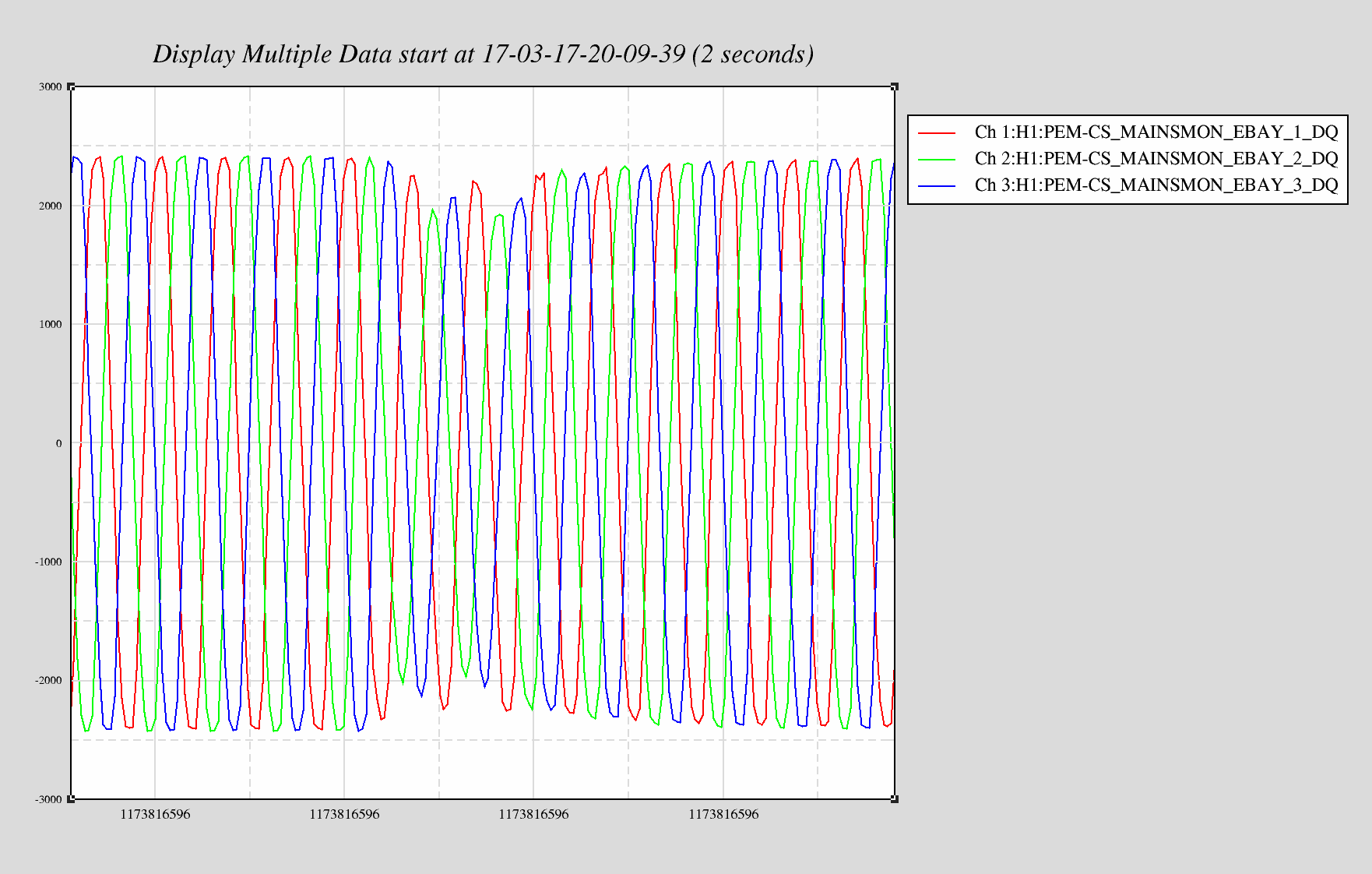
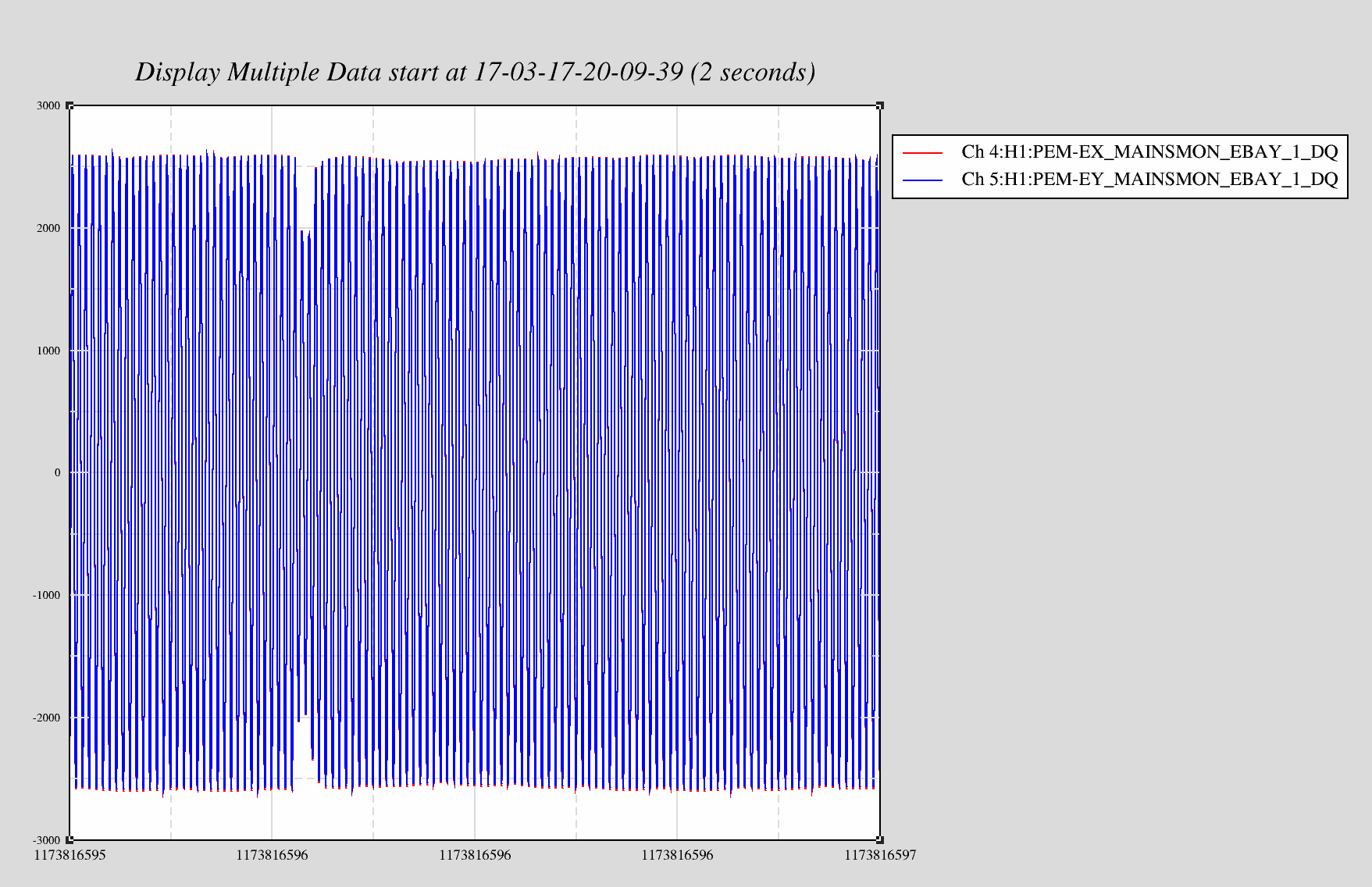
H1 was locked and in observation mode the whole time.
Starting CP3 fill. LLCV enabled. LLCV set to manual control. LLCV set to 50% open. Fill completed in 1259 seconds. LLCV set back to 15.0% open.
Starting CP4 fill. LLCV enabled. LLCV set to manual control. LLCV set to 70% open. Fill completed in 130 seconds. TC A did not register fill. LLCV set back to 43.0% open.
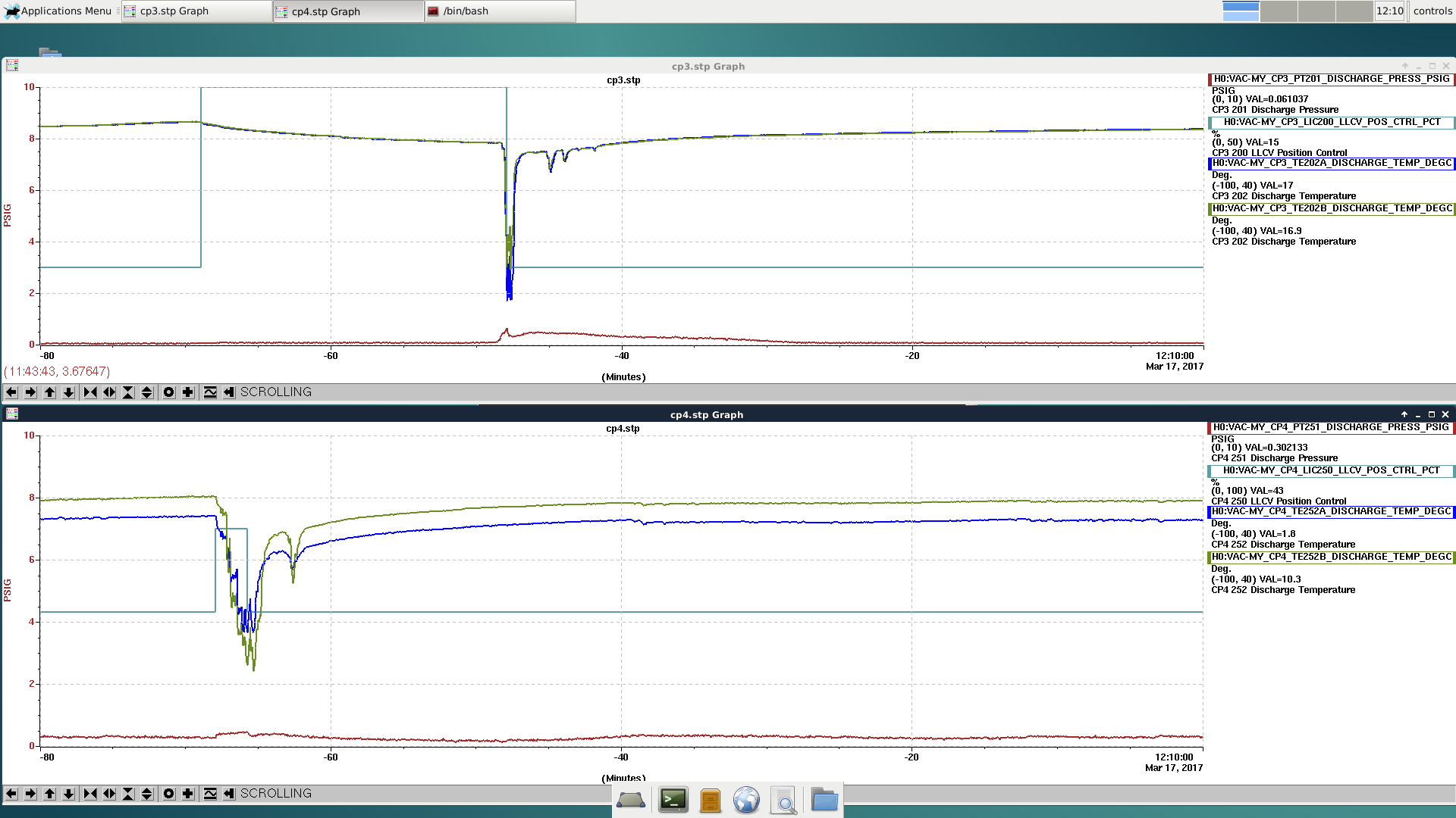
Raised CP3 by 1% to 16% open


Another GRB alert at 15:30 UTC.