TITLE: 10/27 Day Shift: 15:00-23:00 UTC (08:00-16:00 PST), all times posted in UTC
STATE of H1: Commissioning
INCOMING OPERATOR: TJ
SHIFT SUMMARY: Locked at NLN for the first couple hours of my shift. Robert doing PEM injections during this period until lock was broken due to me forgetting to turn off the BRS and Robert getting too close to it. Middle part of the day was Betsy cleaning the PSL viewport. Then we immediately had another EQ when they finished. Relocking commenced in the last couple of hours of my shift.
LOG:
15:00 Robert to LVEA doing PEM injections. Took IFO out of Observing mode due to the injections.
16:40 Robert to EY for PEM inj.
17:45 Betsy, Robert, Peter, Richard to LVEA
17:50 Peter out
17:52 Chandra to MY
19:00 Fil to LVEA
19:08 Fil out
19:30 Fil to LVEA
20:02 Richard to LVEA
20:50 Betsy, Robert done
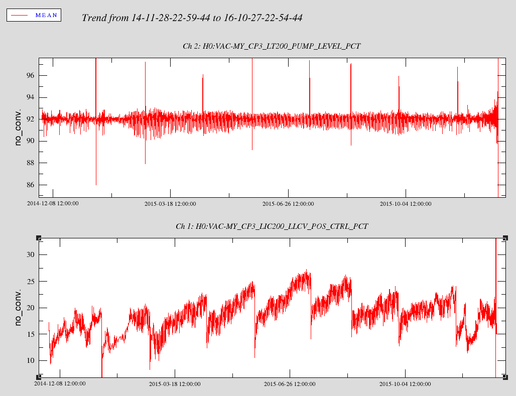
Note: The dust monitor PSL 102 has been alarming on and off all day. See attached screenshot for the trend for today. The thresholds are 70 for minor alarm and 100 for major for both particle sizes.
Betsy, Robert
When the IFO broke lock around 11am, it was decided that we should go clean the viewport window on the South side of the HAM1 chamber which the PSL beam enters (see pix of inspection prompting this at alog 30867). Travis lowered the power of the PSL via the rotation stage to 0.0 and we also locked out the rotation stage and the light pipe out on the floor. We then decoupled the light pipe from the HAM1 port and slid the unit back about a foot. We then proceeded to do a spray-on First Contact cleaning using the "canning cone" as described in procedure E1600263. We let it dry ~30 mins before pulling the sheet off, however 2 small fragments of FC tore off and remained on the window just below center. A second sheet was applied, but it again left a small fragment near the bottom of the window. This time I just painted a stripe across the fragment and pulled it in a 3rd attempt - Robert and I reconciled that this was low enough to be well out of the beam path if I left a streak. Lighting was poor and with laser goggles made for a difficult cleaning. Otherwise, the cone and procedure worked well. I'll add to spray more than 3 layers next time as this may have made for a more sucessful first pull.
Pix are of the 1st and 2nd FC sheet followed by the 3rd little stripe pull. The last picture is the PSL beam centering on the viewport. The beam goes through the viewport just below center, and we see a visible improvement of the scatter points in that area due to the cleaning(s). Note, there is ring of particulate outsid eof the FC sheet pull area, but this is covered by the lightpipe mounting plate which reduced the beam view to the window.
During the downtime while Betsy was cleaning windows, I took charge measurements for both ETMs. The script completed successfully, but I have not looked at the data or processed the results. I'll leave that to those in the know.
Pressure trends since late Feb. 2016 at X and Y end stations, showing events such as NEG regen, 250m IPs on/off, RGA bakes, scheduled power outage. Note: data not available for continuous trend prior to late Feb.
WP 6284
The power cart/transformer along the output arm was powered off this afternoon. The following items were disconnected before powering off the transformer:
HAM 4 Op Lever
HAM 5 Op Lever
HWS Cameras (X&Y)
HAM 6 camera
Jason adviced we could leave the op levers powered off. The cameras power supplies were moved to different circuits and powered back on.
F. Clara, R. McCarthy
FAMIS Request 6869 There is a bump between 20 and 40 Hz in the spectra most clearly for HAM2, HAM5 and HAM6. The ITMY V3 trace is above the nominal.
Thanks Patrick. Jim and I are looking into the bumps in the HAM spectra. The ITMY noise isn't too alarming yet. It is good if the operator compares the current spectra with the previous; something I will do too.
See attached screenshots for trends. FAMIS 4699.
Since the nds2-client-0.13.0 software has caused so much heartburn for so many people, I have reverted back to the previously installed version, nds2-client-0.12.2. This will be effective with all new terminal sessions or logins.
A separate input offset has been added to the AC coupling which is before the on-off switch.
We also commissioned the reference servo which automatically zeroes the output offset, when the second loop is off. The bandwidth is about 1/3 Hz. It requires the excitation input switch to be on, so any analog cabling to this input needs to be disconnected.
Running some experiments with CP4 RE: noise. Set LLCV at 29% open in manual mode with bypass exhaust valve closed to see if signals settle down.
I reset the offset in PID to 32 (was 40) which is closer to nominal value after Dewar fill. I also adjusted the lower limit % open from 20 to 25 to avoid warming transfer line, since the LLCV likes to sit at lower limit in PI mode.
Comparing CP4 pump level in manual mode from June and now. Today is much noisier than back in June.
Here is CP3 trend before it failed last Dec.
We just lost lock, it was probably preventable. There was work being done at ETMY, and looking at a few ISI and SUS signals it looks like someone got too close to the BRS, rung it up enough to push the ISI around and broke the lock. On the attached plot, you can see that for the first minute, the BRS_RX_IN, ISI_ST1_SCSUM channels are all quiet, then the BRS takes off, and this signal gets sent to the ISI through the sensor correction path, the SUS then saturates and breaks the lock. Probably could have prevented this by turning off the sensor correction at ETMY. Wind and microseism are both low enough that this probably wouldn't have broken the lock. The STS also saw some motion, so a state that doesn't use the ground sensor at all would have been appropriate, like WINDY_NOBRSY on the SEI_CONF guardian.
WP #6283 Restarted h1psliss model, which required a DAQ restart.
Kiwamu saked the ops to run some TCS laser noise measurements.
SETUP:
Started the run:
TSC X - Initial Power = 0.2W TSC Y - Initial Power = 0.0W
Time | Power | Time | Power | |
03:00 | 0.3W | 03:00 | 0.1W | |
04:30 | 0.4W | 04:30 | 0.2W | |
At 05:08 Lost lock due to a Mag5.8 EQ in Alaska.
I only managed to get one more data point for both arms:
15:30 utc: TCSx at 0.5W for 90 minutes.
TCSy at 0.3W for 90 minutes.
Oct 28, 10:03UTC, TCSX power set to 0.6, TCSY power set to .4
oct 28, 11:32UTC, change X from 0.6 to 0.7, changed y from 0.3 to 0.4
oct 28, 13:27UTC, tcsx raised to 0.8, tcsy raised to 0.5
As range dropped and arm signals got more noisy I feared H1 was about to lose lock, and touched up TMSX and TMSY alignment. Hopefully this didn't invalidate the data for TCS analysis.
Tweaks by TMS:
Tweaks and TCS changes by timeline:
15:05 UTC: TCSx at 0.9W for 45 min.
TCSy at 0.6W for 45 min.
At 4:43 UTC today (10/30, or (10/29 still PST)), after Robert left, I changed TCSY to .2W, per Cheryl's suggestion left with Corey. TCSX is still at .4W.
Sheila, Kiwmau, Jenne
Once the IFO relocked after our unexplained alignment change, we did a few quick tests. We opened and closed shutters on the DBB, and looked for coherence between DARM and the rack power monitor that we set up yesterday. The DARM noise no longer changes with the state of the DBB shutters, this may be due to the alingment and TCS changes that got rid of our lump in DARM (even at 50W), or due to the PMC realingment that reduced the PMC HV noise in DARM.
However, there is non neglible coherence between the rack power monitor and DARM, from about 320 to 380 Hz. The spectrum of the rack voltage isn't especially noisy at these frequencies.
An attempt to re-measure the PMC HV noise broke the lock when I enabled the excitation.
For Jenne:
Injection for iterative tuning of SRCLFF: started at 8:08:33, went until 8:11:00 UTC on October 27th.
Is this 19V power that only PSL uses?
We are havgin trouble using the lockloss tool, but it has been working since Jamie made a change on October 19th. Is this related to problems with NDS2? TJ and I used lockloss plot earlier in the day today without problems.
Here's what I get:
lockloss select
Segmentation fault (core dumped)
Manually finding a time to ask for:
lockloss -c channels_to_look_at_NOISE_TUNINGS.txt plot 1161580111
.......
INFO: plotting: Adding subplot with the following channels:
H1:LSC-ASAIR_A_LF_OUT_DQ
2016-10-26 22:14:23,904 : NDSAxes : Initializing NDSAxes for the following channels:
H1:LSC-SRCL_GAIN
INFO: plotting: Initializing NDSAxes for the following channels:
H1:LSC-SRCL_GAIN
2016-10-26 22:14:23,938 : NDSBufferDict : Buffers requested at start time 1161580081 and end time 1161580110 for the following channels:
H1:LSC-SRCL_GAIN
INFO: bufferdict: Buffers requested at start time 1161580081 and end time 1161580110 for the following channels:
H1:LSC-SRCL_GAIN
terminate called after throwing an instance of 'NDS::connection::daq_error'
what(): Low level daq error occured [13]: Requested data were not found.
None of the selected channels returned data.
Aborted (core dumped)
The lockloss tool now uses NDS to find the lockloss times. Since both the time determination and data plotting both use NDS and they're both failing, this is definitely an NDS issue. Talk to Jonathan and/or Jim.
Would this be NDS1 or NDS2? Makes a big difference as to where to start debugging. The NDS2 client was updated to nds2-client-0.13.0 on Tuesday, so if lockloss uses NDS2, that's probably where your issue is. Please file an FRS.
NDS1 access with the nds2-client python bindings.
I got suspicious about PMC length locking offset and changed H1:PSL-PMC_INOFFSET.
Increasing it by 1.7mV decreased the PMC length feedback by about a factor of 2, and 1st loop out of loop sensor by a factor of 4 or so, which doesn't make sense. In the attached, red and green are with nominal 3.1mV offset, blue and brown are with 4.8mV.
(After this measurement I noticed that Daniel increased the length gain from 16 to 28dB and forgot to bring it back. This measurement is with 28dB locking gain, but it still doesn't make sense.)
What's the nominal signal level for PMC demod? Is it tiny? When is the last time the PMC demod phase was optimized?
More strange stuff, when we look at the PDA and PDB photodetectors of the first loop in the ISS. In the attached plot, the current traces are with a PMC offset of 3.28mV, reference traces 1-15 are with a 3.58mV offset and reference traces 16-19 are with a 2.98mV offset. With a positive offset change we see a some degradation in PDA at high frequencies, whereas PDB sees significantly less noise. For a negative offset PDA gets a tad bit better and PDB gets worse. Overall PDB shows up to an order of magnitude change in its noise level, whereas PDA only shows up to a factor of 2, going the opposite way. The PMC gain was high and 28dB.
Here is the throughput as function of the offset with a Lorentzian as a fit. The parameters are 0.761, 3.28mV and 4.59mV for the amplitude, offset and HWHM, respectively. Looks like the demodulated signal is only ~9mV pk-pk.
(Keita writing as Sheila)
For those of you who are interested, Daniel's measurement doesn't mean that the noise behavior (in length locking and in intensity noise) makes sense.
(Now writing as myself.)
According to T0900577 (select ilspmc_servo3.pdf) the output of TUF-3 mixer is amplified by a DC gain of 4 and sent to a summation amplifier that has a gain of 10 for the demod and a gain of 1/100 for the offset.
The offset signal seems to be calibrated to represent the offset in the OUTPUT of the summation amplifier (i.e. +-100mV when the offset from DAC is +-10V). Update: I was deceived by HOPR and LOPR of he signal on MEDM being 100 and -100, but the calibration filter of this channel of this gain is just 3.2k, so the number should represent the equivalent offset after the gain of 4 but before the gain of 10.
So this 9mVpp is after the gain of 40 total, the demod right after the mixer should be ~9mV/4/10=230uVpp.
Update: The demod right after the mixer should be ~9mV/4=2.3mVpp.
If this is true this is excessively small and cannot be good, and I wonder if the demod phase is correct or if this is an expected signal level. If this is as designed, can't we increase the modulation depth upstream or something?
(The main document in the above DCC is so-called PDF Portfolio, which is just a document containing all pdfs listed in "other files". If you're on Linux workstations the pdf in the above DCC appears as if it's just a one-page document promoting Adobe product, but if you're using evince document viewer, change "thumbnails" on the left panel to "attachments", and you can select whichever file in the portfolio to view).
Looking at the RF chain:
Therefore, the drive to the modulator seems to be -10 dBm, or 71 mV rms. A standard New Focus 4004 EOM has a modulation coefficient of 25 mrad/V. So the estimated modulation depth is around 1 mrad.
The mixer readbacks are flawed and just see ADC noise. They could use a gain of 200 to get above the ADC noise. Proposed values: