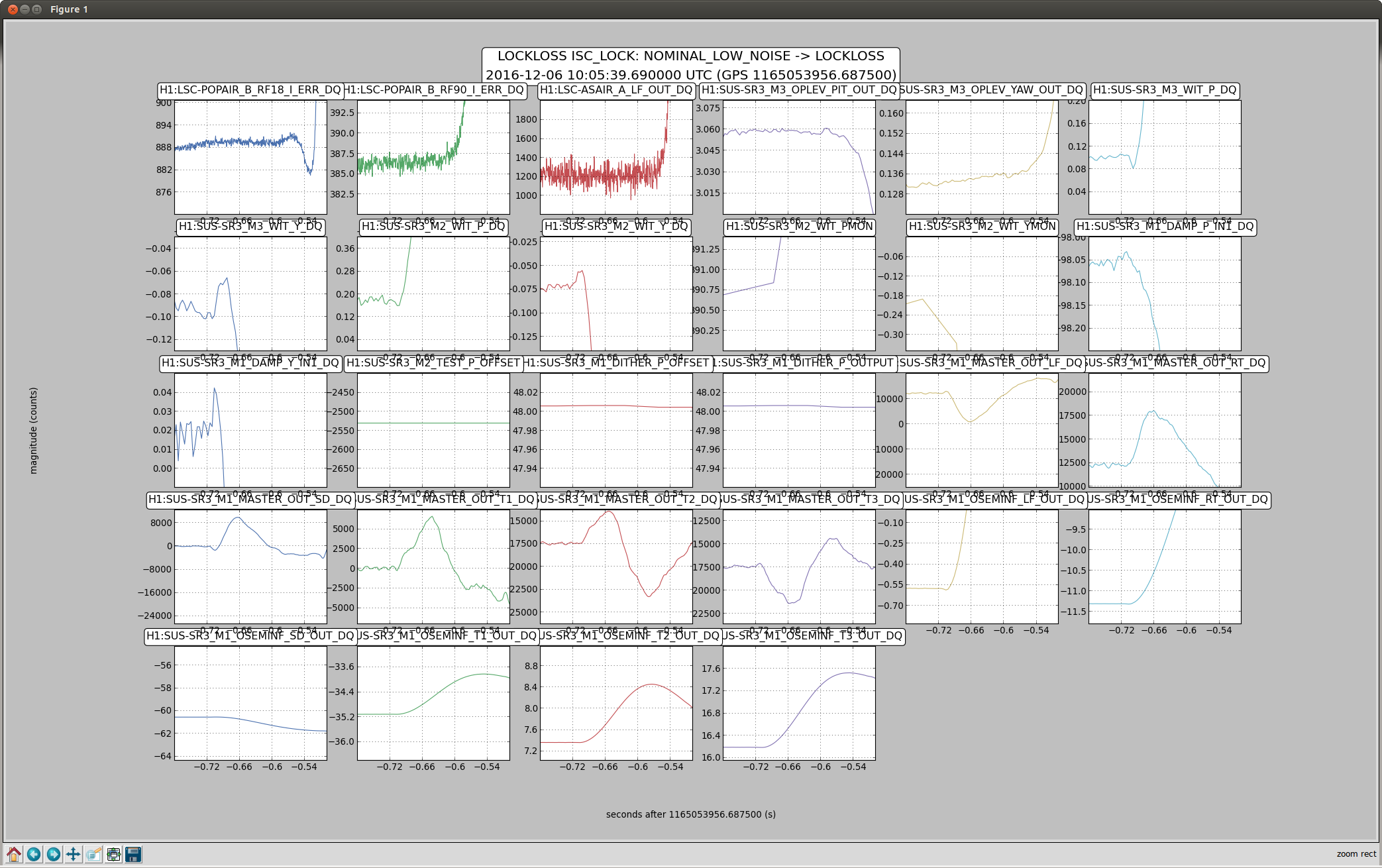
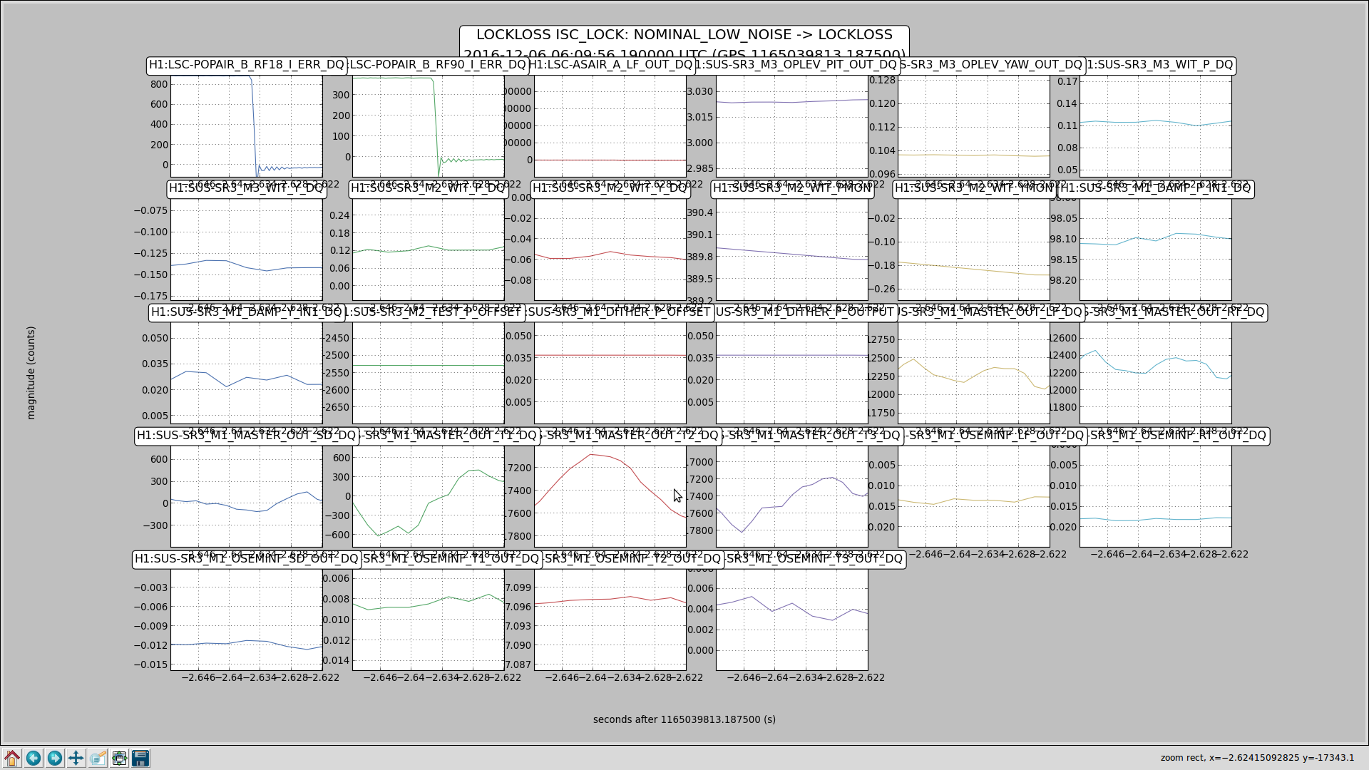
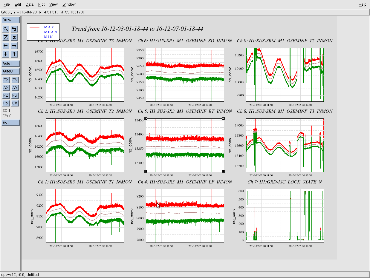
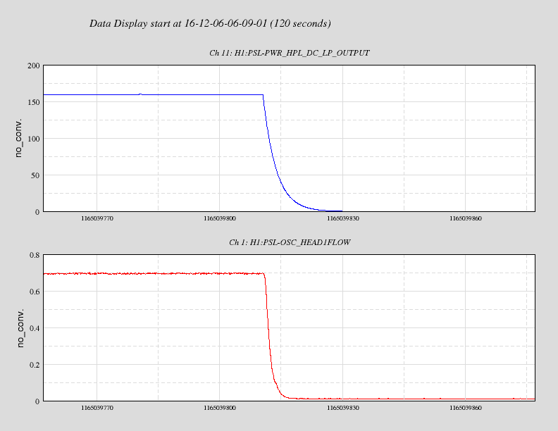
Displaying reports 54761-54780 of 83143.Go to page Start 2735 2736 2737 2738 2739 2740 2741 2742 2743 End
Reports until 12:16, Thursday 18 August 2016
H1 AOS
alastair.heptonstall@LIGO.ORG - posted 12:16, Thursday 18 August 2016 - last comment - 18:14, Friday 19 August 2016(29174)
TCS Y arm laser

[Alastair, Jason, Ben, Vern, Dave]

Thanks to everyone for their help getting this work done.  The Y-arm TCS laser is now running full power, and the table is fully aligned.  The in-loop photodiode is also now working again.  Details below.

Tuesday we discovered the laser on the table (SN 20306-20419D) had previously been paired with the driver that went with the spare laser ( 20816D-20510).  The laser had been outputing 40W at the time.  When the Hanford team had swapped in the 'spare' driver they actually were putting in the one that matched up with the laser (SN 20419D-20306) and the power went down to 16W.  First thing we did on Tuesday was to add irises to the table to define the optical axis after the laser.  We added blocks to the table to define laser position We then swapped in the spare laser (20510-20816D) and aligned to the blocking, and we found the power outputs were ~14W with its mating driver, and ~40W with the driver SN20419D-20306.

Checks on as much of the electronics as we could test showed no problems (RF distribution system, controller voltages, power etc).

Wednesday we decided the fastest way to diagnose the drivers was to swap them in to the working X arm table.  Driver SN 20419D-20306 gave a power output of 58W.  Driver  20816D-20510 gave 42W.  Swapping back to the original X arm laser (SN 20706-21015D) and driver combo gave 60W so at this point we left the X-table in its previous working condition.  Conclusion was that driver SN 20816D-20510 has now given output of ~40W on three separate lasers and appears to have some issue.

Moving back to the Y-table, two issues were noticed.  Firstly there was very minor discoloration on one pin of the power cable for the laser.  Ben also said that the pin looked badly seated and did some corrective work on this (we should check with him if he thinks this needs further work).  Secondly the power meter height was adjusted to make sure the aligment to the laser gave the largest apeture possible - this could with a little misalignment oclude part of the beam.

We repeated measurement of spare laser SN20510-20816D with driver 20419D-20306 getting 49W output.  We then completed the cycle of tests by putting in laser 20306-20419D with its matching driver 20419D-20306 and getting 58.6W output.  It's not clear what fixed the problems - the power cable seems a likely candidate but behavior of the laser still doesn't seem totally consistent with this (if one half of the driver was getting no current we would expect ~25W output).  We also might want to test driver  SN 20816D-20510 to check whether the power connector (which looked okay when visibly inspected) might be a cause for its performance drop.

After the laser swaps the final laser configuration was aligned to the blocking on the table and then to the optical axis with some minor tweaking of the actuators on the first mirror on the table.  The laser was aligned through the whole table.  At the mask we aligned by maximizing transmitted power, then using the FLIR camera on remote desktop (yes this works now - thanks Dave Barker) we tweaked the alignment to make the beam symmetrical after the mask.  We then aligned to the irises at the output of the table which define the optical axis into the vacuum system.  We changed the alignment onto the power meter that gives the power output to the CP because the head was too close to a focus.  We checked the calibration of the power output to the CP and this was confirmed accurate.  Finally we aligned to the two photodiodes on the table.  Inloop was not giving an output but we swapped cables with outofloop and were able to get a signal to align to.

The problems with the in-loop photodiode were traced to being a bad ADC board which has now been swapped for the spare (thanks Ben & Jason for tracking this down).

The Y-table will have the output to the vacuum system unblocked so the system is ready to go.  The laser will be left keyed off, with the rotation stage set to minimum power.  When the system is needed it just needs keyed on at the rack in the LVEA, and then power increased at the rotation stage.

Comments related to this report
evan.hall@LIGO.ORG - 18:14, Friday 19 August 2016 (29213)

I turned on the TCS Y laser and restored the TCS settings to their ER9 values (0.5 W for X, 0.3 W for Y).

The TCS Y rotation stage needs to be recalibrated.

LHO VE
kyle.ryan@LIGO.ORG - posted 11:26, Thursday 18 August 2016 (29173)
Extending bake of Vertex RGA 12 hours longer than initially claimed
Every hour helps - exploiting the water leak recovery
LHO VE
chandra.romel@LIGO.ORG - posted 11:01, Thursday 18 August 2016 (29172)
PT-140A pot adjustment
Gerardo, Chandra

Adjusted potentiometer on PT-140A pirani gauge to bring it back on scale. CCW 4 turns. Closed FRS 6061.

NOTE other gauges that were adjusted a few months ago for calibration:  https://alog.ligo-wa.caltech.edu/aLOG/index.php?callRep=27726
LHO General
ryan.blair@LIGO.ORG - posted 09:21, Thursday 18 August 2016 (29171)
Internet connectivity outage [planned] 0800AM PT - 0900 AM PT
Per WP# 6072 -- 

Activity: PNNL will be coordinating an OTDR test of the fiber pair that feeds the observatory's data connection to make sure that signal strength is appropriate for upgrading to 10Gb/s up from 1Gb/s. Wireless, phones, and internal wired networks at the observatory will be unaffected. Internet access will be interrupted during this work.


Work started at 08:00 PT, completed at approximately 09:10 PT.

If I receive the OTDR data (as viewed from PNNL - ISB2 end), I will attach it to this post.
H1 General
jeffrey.bartlett@LIGO.ORG - posted 18:03, Wednesday 17 August 2016 (29168)
Ops Shortened Evening Shift Summary
Title:  08/17/2016, Evening Shift 23:00 – 07:00 (16:00 – 00:00) All times in UTC (PT)
State of H1: PSL down due to water leak in the HPO   
Commissioning: 
Outgoing Operator:  Corey
 
Activity Log: All Times in UTC (PT)

23:00 (16:00) Start of shift
23:15 (16:15) Terra – Going into the LVEA 
23:51 (16:51) Jason – Out of the LVEA
23:52 (16:52) Ben A. – Cable work around HAM2
23:56 (16:56) Terra – Out of the LVEA
23:58 (16:58) Jason – Going into the LVEA to turn out PSL lights and recover laptop
00:10 (17:10) Jason – Out of the LVEA
00:31 (17:31) Ben – Out of the LVEA

Title: 08/17/2016, Evening Shift 23:00 – 07:00 (16:00 – 07:00) All times in UTC (PT)
Support:   
Incoming Operator: N/A

Shift Detail Summary:  No commissioner work planned due to PSL problems. Ending shift early.

H1 CDS
david.barker@LIGO.ORG - posted 17:55, Wednesday 17 August 2016 (29167)
gust meter reprogrammed

Richard, Fil, Jim W, Jim B, Dave

The voltage outputs from the gust meter when it was installed at EX yesterday did not look correct and did not correlate to wind conditions. Today Jim W brought the unit back to the shop and we tested it with a fan. There was some variation in voltage output but it did not look correct when referencing the manual. Jim Bconfigured the system for RS232 serial communications and logged into the unit. The serial readbacks for wind speed, azimuth and elevation looked correct. Jim reprogrammed the three voltage outputs to be Speed, Azimuth and Elevation. We then set the system back to analog voltage mode, and now the outputs vary by many volts and are V1=speed, V2=azimuth, V3=elevation. We suspect the system lost its programming at some time and was perhaps outputting U,V,W  analog voltages.

The unit is ready for re-install at EX.

H1 CDS
david.barker@LIGO.ORG - posted 17:47, Wednesday 17 August 2016 (29165)
psliss model work

Ben, Dave:

today I modified h1psliss to read the PD5-8 FAST and SLOW channels. On paper it looked like the h1psldbb model was not using the last eight channels of its ADC (the fourth adc, or ADC3). In practice the DB25 connector for the last eight channels of this AA chassis have a cable connected. (Note to team-psl, perhaps the model should be recording these channels). I had already made the model change and restarted the DAQ before we discovered this.

Ben suggests for plan-B we re-use eight of the ISS ADC channels for reading PD5-8. We are going to disconnect the production ISS cables from ADC0 chans 16-23 and replace them with the new ISS PD5-8 cables during tomorrow's test. Specifically ADC0 chans16-19 are PD5-8FAST, chans20-23 are PD5-8SLOW.

I've modified h1psliss, we will wait until tomorrow morning the restart the model and DAQ.

H1 PSL (PSL)
peter.king@LIGO.ORG - posted 17:22, Wednesday 17 August 2016 (29160)
Water leak in the high power oscillator
This morning Ed asked me to look at some trend plots he had just generated.  Clearly noticeable was a sharp
rise in the humidity and a drop in the flow rates for the heads.  I checked the crystal chiller and its
water level was below minimum and the controller displayed an error informing of such.

    Attached is a picture of the burst hose attached to the head 3 water cooling circuit.  This is the same
connection that failed ~2-1/2 years ago.  I do not recall if it has been adjusted since that time.  Although
care is/was taken to prevent twisting of the hose when the fitting is tightened, it is highly likely that
there was a small twist in the hose that exerted a small shear resulting in the tear seen in the picture.

    Also attached is a picture of the 4f lens for head 4, clearly showing some water droplets on it.

    Apart from the obvious step of replacing the hose, the turbine flow sensor for head 4 will also be
replaced.  The laser will take the better part of a day to dry out - to be on the safe side.  All optical
surfaces and the fibre bundle tips will need to be inspected for cleanliness before any operation of the
high power oscillator is contemplated.
Images attached to this report
LHO General
corey.gray@LIGO.ORG - posted 16:04, Wednesday 17 August 2016 (29147)
Shift Summary

(All times in PST)

Today's Headline:  H1 PSL Water Leak.  

H1's state this morning:  DOWN.  ITMx was swinging around, and Kissel cleared history for M0 Lock to calm it down.

Turned off locking servos for the night for ISS, FSS, & PMC.

LHO VE
kyle.ryan@LIGO.ORG - posted 15:26, Wednesday 17 August 2016 - last comment - 17:23, Wednesday 17 August 2016(29161)
Manually over-filled CP3
LN2 at exhaust in 8 minutes
Comments related to this report
chandra.romel@LIGO.ORG - 17:23, Wednesday 17 August 2016 (29163)
Raised LLCV from 19% to 20%
H1 INJ (INJ)
keith.riles@LIGO.ORG - posted 14:31, Wednesday 17 August 2016 (29159)
CW hardware injection files updated in preparation for next test
In preparation for the next CW hardware injection test, the /hinj/Details/pulsar/ subdirectories on h1hwinj1
have been updated. Here are the major changes:
  • Two new subdirectories have been created: O2_H1_test1 and O2_L1_test1. Separate H1 and L1 directories are now needed (as was the case in initial LIGO) since explicit inverse actuation files are used.
  • The signal amplitudes in the PulsarXX_StrainAmp.cfg files in these subdirectories have been doubled for pulsars XX = 0, 1, 2, 4, 7 and 9 and tripled for pulsar 14 with respect to the amplitudes used in O1. These increases are meant to allow quicker validation of injection recover fidelity.
  • Evan's new inverse actuation function for L1 has been copied to the O2_L1_test1 subdirectory.
The symbolic link RELEASE in /hinj/Details/pulsar/ has not been changed yet. When we are ready to perform a test, we will change it from its current pointing to O2test to O2_H1_test1.
H1 SEI (SEI)
cheryl.vorvick@LIGO.ORG - posted 13:52, Wednesday 17 August 2016 (29157)
H1 ISI CPS Noise Spectra Check - Weekly

CPS sensor checks for BSCs and HAMs - measurement taken around now-6hours, or about 14:30UTC today.

Nothing remarkable - spectras look good.

Images attached to this report
H1 SEI
edmond.merilh@LIGO.ORG - posted 13:40, Wednesday 17 August 2016 (29156)
Monthly Trend - HEPI Pump Pressures and Drives FAMIS #4523

Nothing unusual to report. Typical noise at both end stations and data glitching at EY. Corner station pressure shows pump removal as described in Hugh's aLog. Corresponding control activity for this action is also notable in the plots.

Images attached to this report
H1 PSL
edmond.merilh@LIGO.ORG - posted 10:44, Wednesday 17 August 2016 - last comment - 13:26, Wednesday 17 August 2016(29152)
PSL Weekly 10 Day Trends

Peter, Ed

Investigation currently underway regarding potential water leak in HPO.

Images attached to this report
Comments related to this report
corey.gray@LIGO.ORG - 11:18, Wednesday 17 August 2016 (29153)

Water Leak CONFIRMED For H1 PSL!

Peter & Ed are addressing it in the H1 PSL Room.  Vern notified.

Peter said we will be down rest of today and possibly tomorrow.  When TCSy work is complete, we could transition to LASER SAFE....but that will have to be after the active TCSy work.

edmond.merilh@LIGO.ORG - 12:54, Wednesday 17 August 2016 (29154)

This is FAMIS task #6109

corey.gray@LIGO.ORG - 13:26, Wednesday 17 August 2016 (29155)

FRS has been filed for the water leak:  FRS#6063

H1 ISC
sheila.dwyer@LIGO.ORG - posted 23:46, Tuesday 16 August 2016 - last comment - 09:08, Monday 22 August 2016(29142)
some ASC work

Terra, Sheila

Tonight we had trouble engaging the ASC again.

Losing optical gain in POP X

We rang up what we think is a PR3 bounce mode when engaging the ASC the same way as last night.  We found that we could avoid ringing this mode up by keeping the PRC2 gain low (digital gains of -500).  Right before the OMC damage/vent, the POP X path was reworked and the optical gain seemed suspiciously low. 

Tonight we found that the optical gain has decreased even more.  Terra changed the demod phase by dithering PR3 pit (500 counts to M3) and rotated the phase positive 65 degrees, (Q1, Q2, Q3, Q4 from 55, 53, 54, 51 to 120, 118, 119, 116 ) to maximize the signal in I (minimize the Q signal).  The 2 attached figures show Terra's before and after OLG measurements (excitation gain of 50), both with Jenne's gain of -5000, showing a 10dB increase in optical gain which is about what we expected based on the dither amplitude change. 

After optimizing the phase, we did not see the 28 Hz mode get rung up, but this seems to come and go because we also didn't see it yesterday.  We quickly tried moving L2 on the POP X path, while watching the amplitude of the PR3 dither line in the POP X signal.  We moved the lens about 4 inches closer to POP X and about 3 inches further away, and didn't find any location that had more signal for PR3 so we replaced it as we found it. 

We are going to leave the IFO locked in DC readout 2 Watts with the request set to down so that it will not try to relock. The noise is bad as expected. 

Images attached to this report
Non-image files attached to this report
Comments related to this report
daniel.sigg@LIGO.ORG - 09:21, Wednesday 17 August 2016 (29148)

POPX whitening gain is 0dB but should be odd, see alog 26307. FRS 6057 filed.

sheila.dwyer@LIGO.ORG - 14:20, Wednesday 17 August 2016 (29158)

The whitening gain on POP X was changed from a gain step of 7 (21 dB) to 0 (0dB) on August 12th.  This whitening chassis has a problem and we must use odd gain settings, or else it will return an error and not set the gains equally on all quadratns, as Keita and Hang noted 26307

The change in gain probably happened during a beckhoff restart for the shutter code, but we could have been saved from this problem by SDF.  I cannot find a record for these whitening chassis in any SDF table. 

Also, this does not explain the drop in gain that Jenne saw, which happened before the whitening settings changed. 

sheila.dwyer@LIGO.ORG - 17:34, Wednesday 17 August 2016 (29164)

The stuck whitening gain bit is the LSB of the Q3 channel. In the past this was typically an indication of a cable problem (short).

sheila.dwyer@LIGO.ORG - 18:37, Wednesday 17 August 2016 (29170)

Sheila Daniel Terra

Connected the AM laser to the POP X head, and saw that we have very similar response in the electronics to what Evan measured in 27069

we had 3.3 mW out of the AM laser with a whitening gain of 21 dB, used -40 dBm of RF drive at 45.501150 MHz.  We saw about 600 counts on each quadrant (except quadrant 3 which had 350 counts and also the least amount of DC light because of way the laser was mis centered on the diode).  

We saw that there are rather large offsets when we changed the whitening gain, so Daniel reset the offsets.  The large offsets might have contributed to problems last night, along with confusion about the whitening gain. 

Also, we remembered that a factor of 6.7 of the mystery gain loss was due to adding a beamsplitter and forgetting to comensate for it on July 11. 

(Edit:  Actually, Haocun and I did remember to correct for this gain change, we just compensated for it in the digital loop gain. )

So to summarize:

loops were intially commisioned with a whitening gain of 21, a digital gain of -21, a 1 Hz ugf, and electronics gain similar to what we have now. (late may)

Edit: loops were originally commisioned with a filter gain of -200 for pit, -0.1 in the input matrix, an analog gain of 21 dB, and the WFS head electronics performing in a way simlar to what we have now.  This is when the reference that I think Jenne used was saved, and within a few days the pit input matrix was reduced by a factor of 2.

Edit: Around June 16th, we had difficulty staying locked when these loops were engaged, which was noted in the alog.  Terra and I just looked at trends of the filter gains, and it seems like we also reduced the digital gain from -220 to -3.4 although this was not noted in the alog.  This, together with the input matrix change explains most of the missing gain that Jenne found. 

On July 11th I forgot to compensate for the beamsplitter causing a gain reduction of 6.7 that no one noticed.

On July 26th, Evan and Keita relocated POP X and Jenne noticed that the digital gain had to be increased by a factor of 250 (or 500 for yaw) to keep the ugf the same.

August 12th the whitening gain was reduced to 0 dB from 21 dB by mistake in a beckhoff reboot.

August 16th Terra and I noticed this further reduction in gain, which is explained by the whitening gain.  We also changed the demod phase which increased the gain by about 10 dB.  We checked that small movements of the L2 don't change the optical gain much, and moving it by a few inches can decrease the signal. 

So, we are missing about a factor of 40 gain, which we cannot explain with electronics.

In the end only a factor of 2 of Jenne's gain change in unexplained.  It seems that we have had stable high power locks with both the high gain and low gain settings for PRC2, so we can decide which we want to use.  We also should have a factor of 3 increase in gain because of the phasing Terra and I did. 

keita.kawabe@LIGO.ORG - 17:18, Friday 19 August 2016 (29211)

More complicated than that.

  Whitening
(dB)
POPX digital gain
before rotation
Input matrix PRC2_P_GAIN

BS
(15% transmission)

Overall gain
relative to original
alog
Originally 33 1 -1 -220 none NA  
May 24 ~1:02 33 1 -0.05 -220 none 0.5  
Jun. 17 33 1 -0.05 -3 none 6.8E-3  
Jun. 22 ~noon 21

2.8

-0.05 -3 none 4.8E-3 27901
Jul. 11-12 21 2.8 -0.05 -21 inserted 5.0E-3 28324
Jul. 27 ~4:20 21 2.8 -0.05 -5000 inserted 1.2 28666

No mystery optical/electronic gain reduction any more. Maybe a factor of 1.2 came from the rework on the table.

It's not clear to me why the PRC2 filter gain was reduced by a huge amount on Jun. 17 but I haven't searched through alog.

keita.kawabe@LIGO.ORG - 09:08, Monday 22 August 2016 (29223)

Typo in the above table, originally the input matrix was -0.1, not -1.

H1 PEM
filiberto.clara@LIGO.ORG - posted 14:41, Tuesday 16 August 2016 - last comment - 15:32, Thursday 18 August 2016(29135)
PEM Power Supplies
PEM power supplies in the CER mezzanine were swapped out for Kepco model JQE supplies. This model is a 1/4 rack version, and allows for four power supplies to be mounted on one shelf. This is to make room for the ±24V power supplies that will be used to power Beckhoff/Baffle PD Amplifier/ Spool X/Y camera ect. All PEM instrumentation microphones, magnotometers, ect. were powered down from around 10:30 am to 1:00 pm. All power is now restored.
Comments related to this report
terra.hardwick@LIGO.ORG - 18:47, Tuesday 16 August 2016 (29141)

Fil, Terra

I did a quick check of power spectra for all corner station mics and mags, before and after power supply swap. Attached spectra show pre-swap in darker colors as references, post-swap in lighter.

Found post-swap saturation in several mags, strongest in MAG_LVEA_INPUTOPTICS (first attachment at 21:03 UTC ). Fil switched this mag to battery power, which has temporarily fixed the problem (second attachment at 23:03 UTC). He took a look at the mag box in the lab but found nothing wrong. We left it battery powered for now. Will investigate more tomorrow.

Additionally, it looks like MIC_LVEA_HAM7 got disconnected around 23:03 UTC (top right of second attachment).

Images attached to this comment
terra.hardwick@LIGO.ORG - 17:08, Wednesday 17 August 2016 (29162)

Channel 2 of AA Chassis S1300104 found to be bad.

MIC_LVEA_HAM7 started negatively railing yesterday ~3 hours after the power supply swap, trend attached (first drop then raise is from power supply swap). Turns out that AA channel has gone bad (bottom most AA chassis in PEM rack). Fil will pull it and have a look tomorrow morning. 

Images attached to this comment
terra.hardwick@LIGO.ORG - 15:32, Thursday 18 August 2016 (29178)

AA chassis repaired, HAM7 mic back up and running. MAG_LVEA_INPUTOPTICS was also fixed. At this point, all corner station mics and mags are running well. Attached are power spectra for all.

Images attached to this comment
H1 ISC
keita.kawabe@LIGO.ORG - posted 18:25, Friday 29 July 2016 - last comment - 18:09, Wednesday 17 August 2016(28752)
Suspicious POPX

After I and Evan relocated POP-X and POP-L2, Jenne increased the ASC gain of POP-X by a factor of 250 for PIT and 500 for YAW (alog 28666) just to get back to the old UGF, which sounded crazy to me as I didn't expect much change in Gouy phase.

Just to see if my assumption was wrong and we got super unlucky, I calculated the Gouy phase of the POPAIR path, and it seems like there shouldn't be much change.

In the first attachment, left column is the current configuration, right is the old one. Bottom is the entire POP path from ITM to the ISCT1, and top is the zoomed-in view from HAM1 to ISCT1.

POP-L2 was placed far enough from the waist originally. This lens was moved farther from POP-L1 by 4 inches later, which should have increased the Gouy phase, but it's only 9 degrees. The beam diameter is 2mm now instead of 4mm but that should be OK. These don't explain the crazy decrease of the optical gain.

Funny thing is that the POP-X spectrum itself looks almost the same before and after the relocation (second attachment), so I'm kind of dubious that the optical gain is lost.

It's not totally impossible, but very unlikely, that the Gouy phase was not great to start with, e.g. 81 degrees for the DOF we want to see, and after the change it became 90 degrees.

Images attached to this report
Comments related to this report
sheila.dwyer@LIGO.ORG - 18:09, Wednesday 17 August 2016 (29169)

Today talking with Terra and Daniel, I remembered that we added a beamsplitter to the POP path to void saturating, and apparently I forgot about adding the factor of 6.7 to compensate for lost gain to the POP X RF loops.  (alog 28324)  So this explains a factor of 6.7 lost gain, but not all the gain that Jenne had to add to the loops.

Displaying reports 54761-54780 of 83143.Go to page Start 2735 2736 2737 2738 2739 2740 2741 2742 2743 End