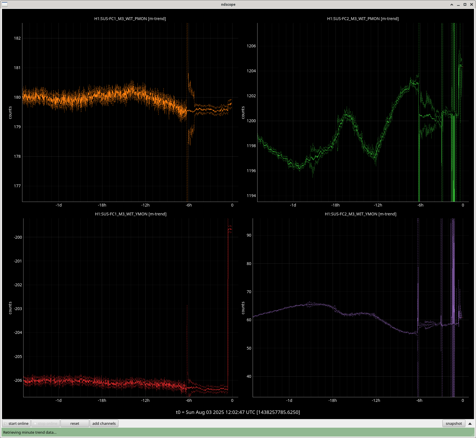
There were some light end station VAC pump checks/disassemblies but they didn't seem to affect the measurements, the error bars are much better/smaller than the last time when it was windy out.
ETMY's charge is high (>50V) on half of the quadrants, it appears stable if we discount the previous bad measurement.
ETMX's charge is hovering within +/-10V of 50V except for LR_P, it also appears stable ignoring the previous measurement.
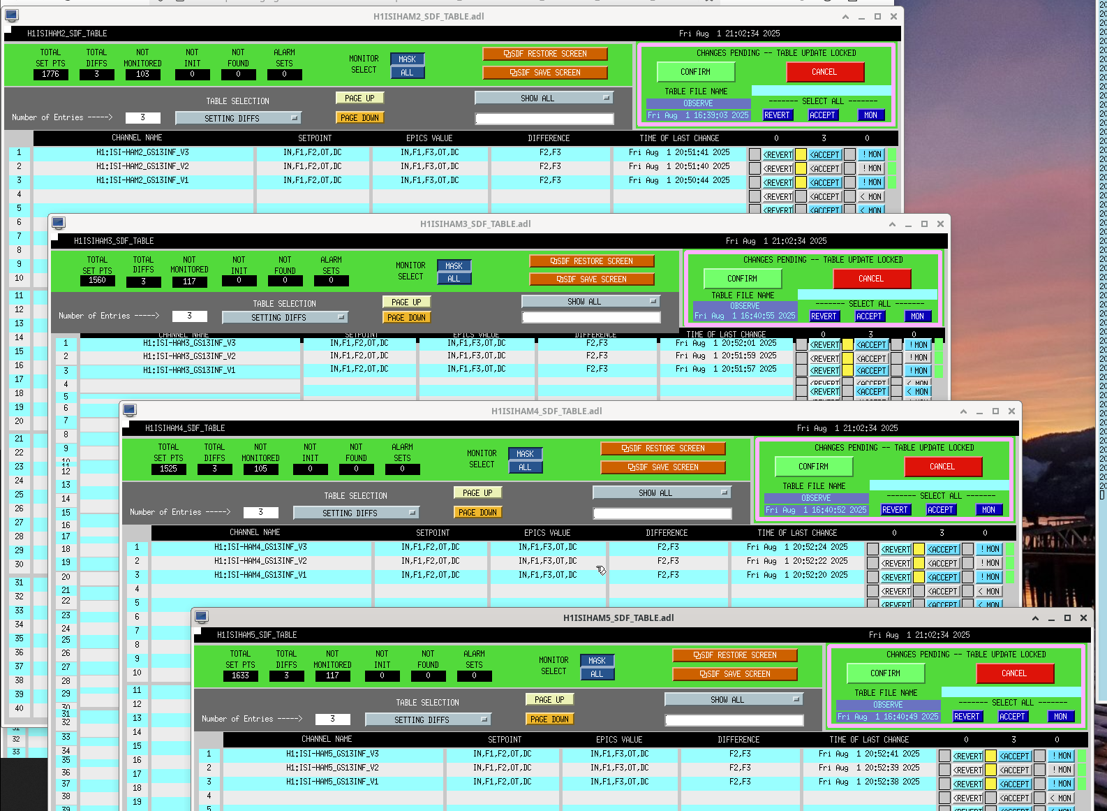
J. Kissel Following LHO:85198, I've changed the sign the OSEM2EUL and EUL2OSEM matrix elements that transform from "SD" to "T" and vice versa, as SRM is one of the few HSTSs that have their "SD" OSEM mounted on the "Opposite Side," (again see G2402388 and E1100109). Matrix Element Was In now H1:SUS-SRM_M1_OSEM2EUL_2_6 -1.0 +1.0 H1:SUS-SRM_M1_EUL2OSEM_6_2 -1.0 +1.0 I attach a comparison two sets of new health check TFs, one UNDAMPED and the other DAMPED against a previous 2024 measurement. This metric (and any other metric we have) shows no change, as expected (see "Shouldn't we have discovered this with the 'health check TFs?'" section of LHO:85198). The SUS was in the new "HEALTH CHECK" guardian state, but with the alignment offsets ON*** and all DOF's worth of damping loop gains set to -0.5 per nonimal since 2023 (see LHO:85273). The ISI/HEPI system was isolated, but with sensor correction OFF because it's maintenance day. *** "It is known" that in the current mechanical alignment vs. OSEM position, that with the alignment offsets OFF, the LF and RT OSEMs aren't far above ADC 0 counts, and thus the magnitude of the TFs drops by almost a factor of two, and coherence gets worse even with twice the excitation amplitude. I also attach SDF screenshots of me accepting these new values in the safe and OBSERVE .snap files. The data sets are committed to /ligo/svncommon/SusSVN/sus/trunk/HSTS/H1/SRM/SAGM1/Data/ 2025-06-24_1558_H1SUSSRM_M1_WhiteNoise_L_0p02to50Hz.xml 2025-06-24_1558_H1SUSSRM_M1_WhiteNoise_P_0p02to50Hz.xml 2025-06-24_1558_H1SUSSRM_M1_WhiteNoise_R_0p02to50Hz.xml 2025-06-24_1558_H1SUSSRM_M1_WhiteNoise_T_0p02to50Hz.xml 2025-06-24_1558_H1SUSSRM_M1_WhiteNoise_V_0p02to50Hz.xml 2025-06-24_1558_H1SUSSRM_M1_WhiteNoise_Y_0p02to50Hz.xml 2025-06-24_1629_H1SUSSRM_M1_WhiteNoise_L_0p02to50Hz.xml 2025-06-24_1629_H1SUSSRM_M1_WhiteNoise_P_0p02to50Hz.xml 2025-06-24_1629_H1SUSSRM_M1_WhiteNoise_R_0p02to50Hz.xml 2025-06-24_1629_H1SUSSRM_M1_WhiteNoise_T_0p02to50Hz.xml 2025-06-24_1629_H1SUSSRM_M1_WhiteNoise_V_0p02to50Hz.xml 2025-06-24_1629_H1SUSSRM_M1_WhiteNoise_Y_0p02to50Hz.xml
Laser Status:
NPRO output power is 1.859W
AMP1 output power is 70.23W
AMP2 output power is 139.9W
NPRO watchdog is GREEN
AMP1 watchdog is GREEN
AMP2 watchdog is GREEN
PDWD watchdog is GREEN
PMC:
It has been locked 7 days, 0 hr 17 minutes
Reflected power = 23.15W
Transmitted power = 105.5W
PowerSum = 128.6W
FSS:
It has been locked for 0 days 2 hr and 28 min
TPD[V] = 0.8134V
ISS:
The diffracted power is around 3.8%
Last saturation event was 0 days 2 hours and 28 minutes ago
Possible Issues:
PMC reflected power is high
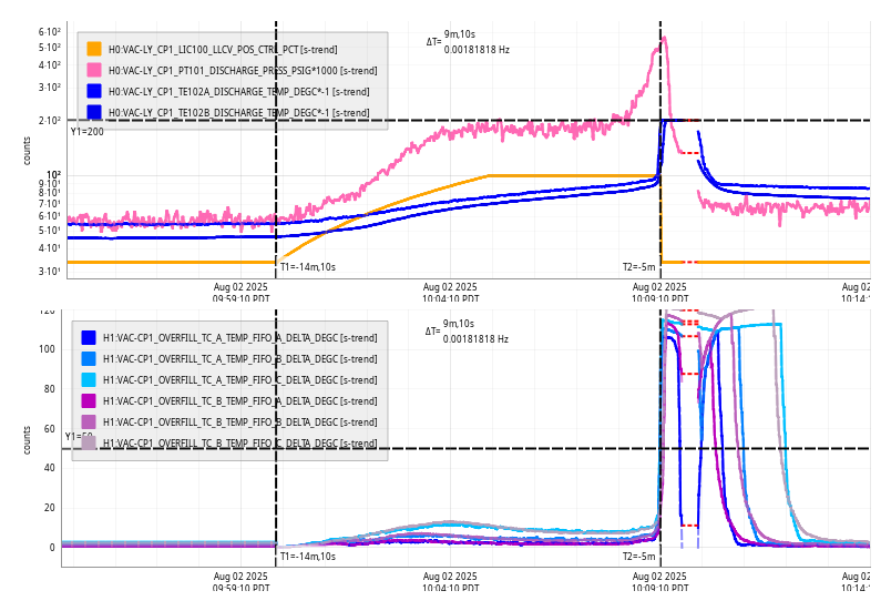
Tue Jun 24 09:59:20 PM PDT 2025
For channel(s):
H0:VAC-LY_CP1_100_LLCV_MAN_POS_PCT
H0:VAC-LY_CP1_LT105_DEWAR_LEVEL_PCT
H0:VAC-LY_CP1_LT105_DEWAR_LEVEL_PCT_ERROR
H0:VAC-LY_CP1_PT101_DISCHARGE_PRESS_PSIG
H0:VAC-LY_CP1_PT101_DISCHARGE_PRESS_PSIG_ERROR
H0:VAC-LY_CP1_TE102A_DISCHARGE_TEMP_DEGC
H0:VAC-LY_CP1_TE102A_DISCHARGE_TEMP_DEGC_ERROR
H0:VAC-LY_CP1_TE102B_DISCHARGE_TEMP_DEGC
H0:VAC-LY_CP1_TE102B_DISCHARGE_TEMP_DEGC_ERROR
H0:VAC-LY_GV5_ZSM159A_VALVE_ANIM
H0:VAC-LY_GV6_ZSM169A_VALVE_ANIM
H0:VAC-LY_Y3_PT114B_PRESS_TORR
H0:VAC-LY_Y3_PT114B_PRESS_TORR_ERROR
H0:VAC-LY_Y4_PT124B_PRESS_TORR
H0:VAC-LY_Y4_PT124B_PRESS_TORR_ERROR
H1:DAQ-H1EDC_CHAN_NOCON
J. Kissel Just stating for the record, as the 2023 aLOG records are a bit unclear (LHO:72106 and LHO:72130 are all I could find, and they claim -0.2), I state here that all DOFs of H1 SUS SRM's M1 damping loop gains have been at -0.5 since 2023-04-21 22:49 UTC, prior to that, they were the -1.0 as designed (see 2022 upgrade to "level 2.0", LHO:65310). See attached trend confirming this to be true.
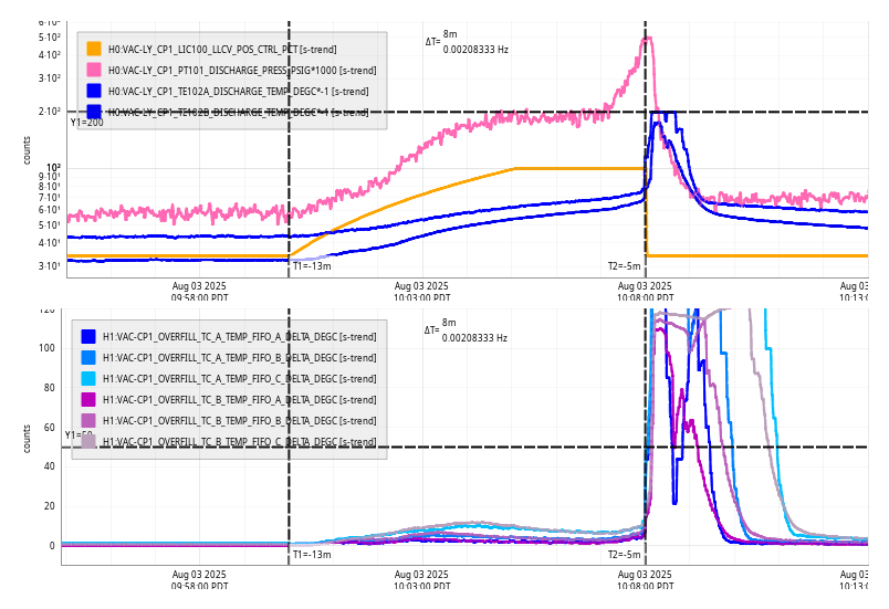
Tue Jun 24 09:40:55 2025 INFO: Fill completed in 8min 51secs
Today's fill was ran at 09:33 to complete it before Patrick started his work on h0vacly.
Per WP 12570 we stopped the cameras on h1digivdeo[45] and updated the pylon and pylon-camera-server software. This was to bring in a fix in the pylon library for leaked file descriptors when a camera dropped and reconnected.
Last week we just restarted the software to close all the leaked file descriptors. This should solve the problem. This was not a feature update of the camera software, just a rebuild against a newer pylon library.
This was done 8:50-9:00am local time (16:00 UTC).
The procedure was to:
1. run apt-get update
2. stop all the camera processes via the management web page
3. run apt-get install pylon pylon-camera-server
4. restart all the camera processes via the management web page
5. spot check a few cameras to make sure things come back.
For posterity, pylon was updated to 8.1.0 and pylon-camera-server was updated to 0.1.18
A FAMIS task reminded us to update the leap second files on some core infrastructure that we don't update much.
These were updated either by updating the tzdata package or copying over a current leap-seconds.list + leapseconds file to /usr/share/zoneinfo.
h1daqd* machines where updated to tzdata 2025b-0+deb11u1
h1guardian1 already had this applied already.
Erik is updating h1vmboot5-5 and it's diskless roots
h1fs[01] have been updated
h1hwinj1 has been updated
h1digivideo2 has been updated
h1hwsmsr & h1hwse[xy] have been updated
h1fescript0
This is regular maintenance. An example of what happens when we miss this is in https://alog.ligo-wa.caltech.edu/aLOG/index.php?callRep=82769
TITLE: 06/24 Day Shift: 1430-2330 UTC (0730-1630 PST), all times posted in UTC
STATE of H1: Observing at 149Mpc
OUTGOING OPERATOR: TJ
CURRENT ENVIRONMENT:
SEI_ENV state: CALM
Wind: 5mph Gusts, 2mph 3min avg
Primary useism: 0.01 μm/s
Secondary useism: 0.06 μm/s
QUICK SUMMARY:
Currently Observing and have been Locked for almost 4 hours. Magnetic injections just finished.
Workstations updated and rebooted. This was an OS packages update. Conda packages were not updated.
The FC TRANS GR (CAM33) camera looks to have crashed or at least the channels for its controls were no longer accessable. The image was still viewable, at least from the screenshots fom. i restarted the process via the browser interface linked from the camera overview and that did the trick. Back to Observing at 0730UTC.
TITLE: 06/24 Eve Shift: 2330-0500 UTC (1630-2200 PST), all times posted in UTC
STATE of H1: Lock Acquisition
INCOMING OPERATOR: TJ
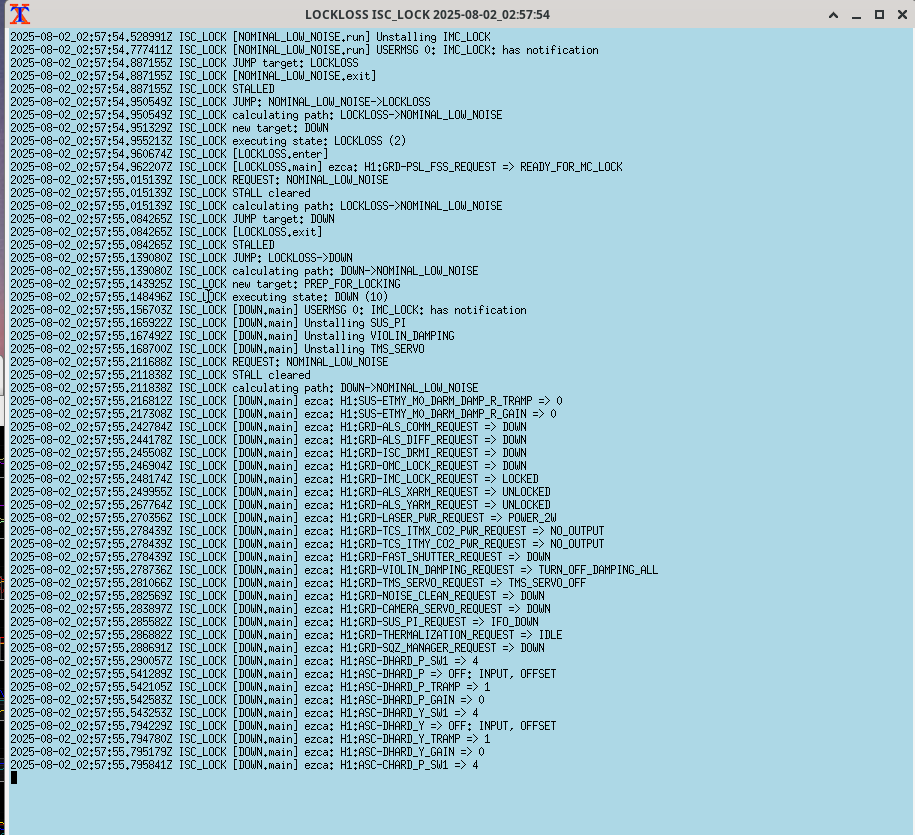
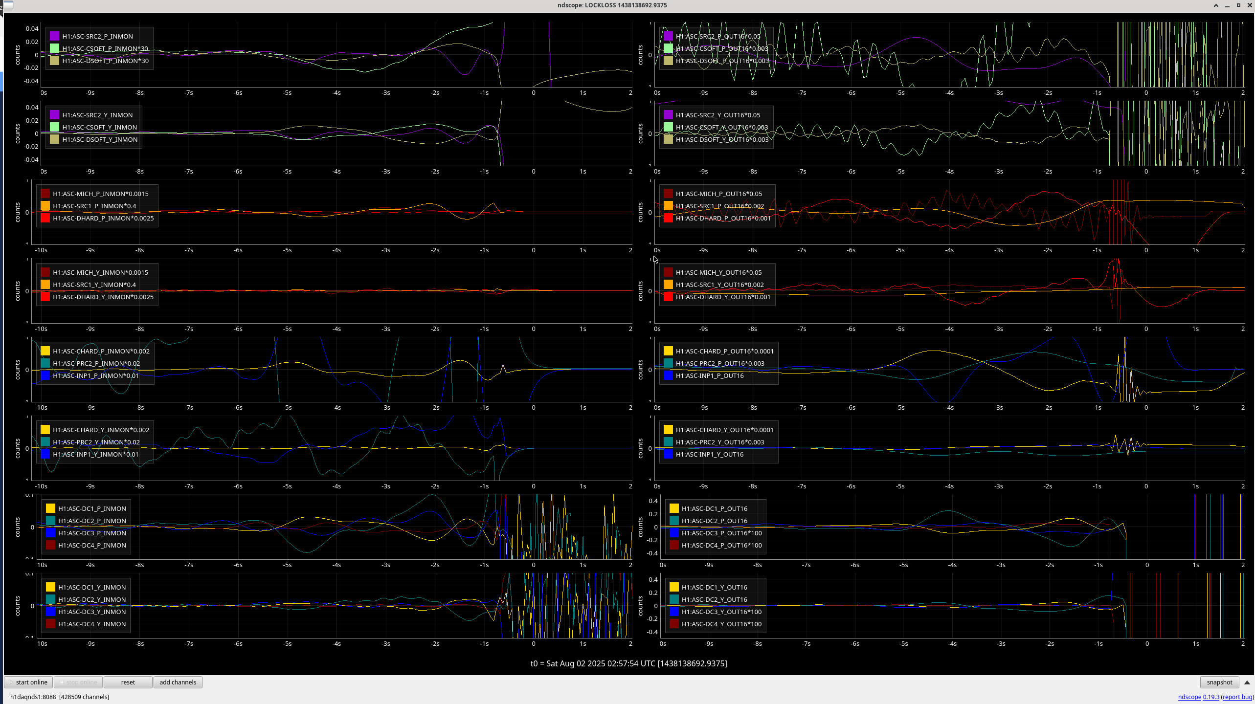
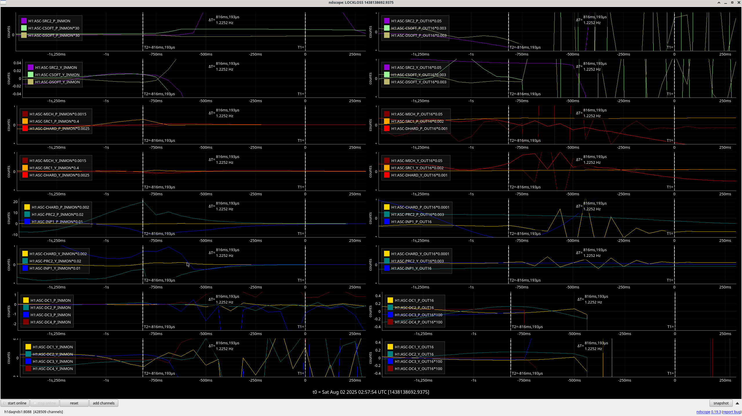
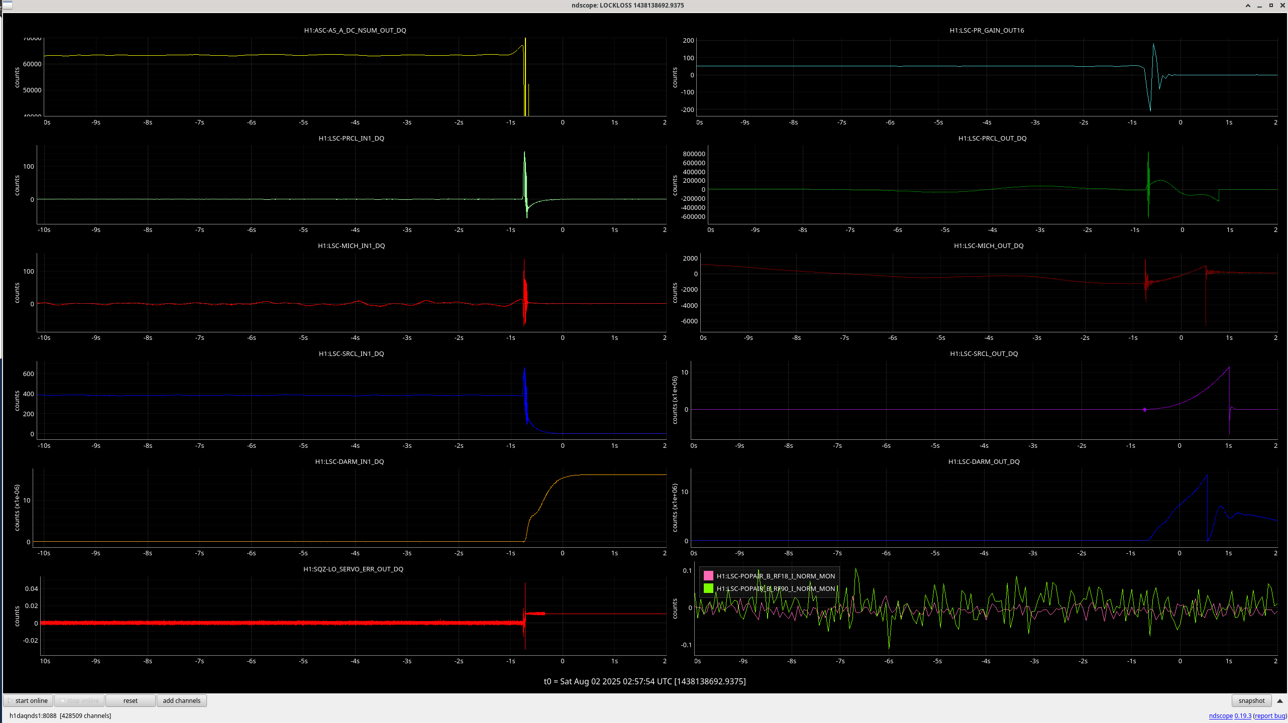
SHIFT SUMMARY: H1 lost lock due to one or more earthquakes this evening and is still working on relocking. Despite everything running smoothly and automatically on the way back up, there was a lockloss for some reason during MAX_POWER as I type this, so H1 will be trying again on its own.
Lockloss @ 03:03 UTC after almost 6 hours locked - link to lockloss tool
Several quakes rolling through around this time; hard to say which was the real cause but likely a M5.7 in the Caribbean.
(Jordan V., Travis S., Gerardo M.)
Up to this morning the volume of HAM1 was being pumped by a turbo pump and an ion pump, we have removed the turbo pump, we closed its isolation valve, but the system remains on (SS500 cart with scroll pump, and turbo pump are still ON). The turbo pump was isolated to let the ion pump take over the pumping of HAM1, it took a few hours but the ion pump seems to be doing good managing the internal pressure of HAM1, see attached trend, we did have a small anomaly that can be noted on the same trend data, a little spike, we are looking into it. If the pressure continues to improve, we'll be able to turn off all other auxiliary systems and decouple everything from the turbo pump tomorrow.
FAMIS 31091
Nothing major to report; things are looking stable this week.
TITLE: 06/23 Day Shift: 1430-2330 UTC (0730-1630 PST), all times posted in UTC
STATE of H1: Observing at 148Mpc
INCOMING OPERATOR: Ryan S
SHIFT SUMMARY: Currently Observing at 150Mpc and have been Locked for just over 2 hours. Nothing too out of the ordinary today. We had two locklosses, but relocking was relatively straightforward.
LOG:
14:30 Observing at 140Mpc and have been locked for 11 hours
14:54 Out of Observing due to SQZ unlock
15:00 Staying out of Observing to start Commissioning - went to FIS
17:18 Lockloss (85239)
- Holding in DOWN for a bit while VAC team closes the pump valve for HAM1
- Running an initial alignment (accidentally did it before the newly mandated 30-60 BS cooling period but it went okay)
18:52 NOMINAL_LOW_NOISE
19:58 Lockloss (85249)
21:23 NOMINAL_LOW_NOISE
21:25 Observing
| Start Time | System | Name | Location | Lazer_Haz | Task | Time End |
|---|---|---|---|---|---|---|
| 14:41 | FAC | Nellie | MY | n | Tech clean | 15:29 |
| 14:55 | FAC | Kim | MX | n | Tech clean | 15:49 |
| 16:13 | PCAL | Tony | PCAL Lab | y(local) | Packing up PCAL stuff | 17:06 |
| 16:52 | ISC | Sheila | LVEA | n | Plugging in a cable (in 10 mins ago) | 16:52 |
| 17:21 | VAC | Jordan, Travis | LVEA | n | Closing out pump valve | 17:29 |
| 20:21 | ISC | Keita | OpticsLab | y(local) | ISS array | 21:37 |
| 20:26 | FAC | Tyler | MX | n | Bees | 20:41 |
| 21:09 | Mitchell, Jason | MY | n | Verifying some stuff | 22:20 |
We're assembling the first unit that incooporates all upgrades including the QPD tilt and here are minor problems we've stumbled upon. (No ISS array unit with an upgrade to tilt the QPD (E1400231) has been assembled before as far as I see and nobody seems to have cared to update all drawings.)
First picture is an example of the QPD before upgrade. QPD assembly (D1400139) and the cable connector assembly (D1300222) are mounted on the QPD platform by the QPD clamp plate (D1300963-v1, an older version) and a pair of split QPD connector clamps (d1300220). Two pieces of kapton insulation sheets are protecting the QPD assy from getting short-circuited to the platform.
After the upgrade, the QPD assy sits on top of a tilt washer (D1400146, called beveled C-bore washer) that tilts the QPD by 1.41deg in a plane that divides YAW and PIT plane by 45 degrees (2nd picture). The bottom kapton will go between the washer and the QPD platform plate.
Problem 1: Insulation between the QPD clamp and the QPD pins is a bit sketchy.
Titled QPD means that the bottom of the QPD assy is shifted significantly in YAW and PIT. A new asymmetric QPD clamp plate with tilted seating for the screws (D1300963-v2) has been manufactured to accommodate that. But we have no record of updated kapton insulators, so the center of the clamp bore doesn't agree with the kapton (3rd picture, note that the QPD rotation is incorrect in this picture, which had to be fixed when connecting the cable). Since the tilt washer is not captured by anything (it's just sandwiched between the clamp and the platform plate), it's not impossible to shift the QPD assy such that some of the QPD pins will be grounded to the clamp and thus to the QPD platform plate.
You must check that there's no electrical connection between the QPD assy and the platform each time you adjust the QPD position in the lab.
Problem 2: New QPD connector clamp posts are too long, old ones are too short.
Old posts for the QPD connector are 13/16" long, which is too short for the upgrade because of the tilt washer, see 4th picture where things are in a strange balance. It seems as if it's working OK, but you can wiggle the post a bit so the post slides laterally relative to the clamp and/or the platform, it settles to a different angle and suddnly things become loose. To avoid that, you tighten the screws so hard that they start bending (which may be already starting to happen in this picture).
Also, because the clamp positions are 45 degrees away from the direction of tilt, one clamp goes higher than the other.
To address these, somebody procured 1" and 15/16" posts years ago, but they're just too tall to the point where the clamps are loose. If anything, what we need are probably something like 27/32" and 7/8" (maybe 7/8" works for both).
We ended up using older 13/16" posts, but added washers. Two thin washers for the shorter clamp, two thin plus one thick for the taller one (5th picture). This works OK. Shorter screw is the original, longer screw was too long but it works.
Problem 3: It's easy to set the rotation of the QPD wrong.
When retrofitting the tilt washer and the newer QPD clamp plate, you must do the following.
I screwed up and put the QPD on the connector at a wrong angle. It's easy to catch the error because no quadrant responds to the laser, but it's better not to make a mistake in the first place. It will help if the QPD assy barrel is marked at the cathode-anode1 corner.
It seems that D1300222 and D1101059 must be updated. Systems people please have a look.
D1300222: A tilt washer (D1400146), a new QPD clamp (D1300963-v2) and two sheets of kapton insulation are missing. Spacers are longer than 13/16".
D1101059: Explicitly state that part #28 (D1300963, QPD clamp) must be D1300963-v2.
I installed the beam dumps (which are two plates of filter glass, probably from Schott?) for the array after cleaning them according to E2100057.
There are marks that look like water spots and/or some fog that couldn't be removed by repeated drag wiping with methanol (see picture).
After installation, I found that these plates are very loosely captured between two metal plates, see the video, this seems to be by design. I don't like it but the same design has been working in chamber for years.
J. Kissel I'm building up some controls design documentation for the derivations of the OSEM2EUL / EUL2OSEM matrices for existing suspension types (see G2402388), in prep for deriving new ones for e.g. the HRTS and if we upgrade any SUS to use the 2-DOF AuSEMs. In doing so, I re-remembered that the HLTS, HSTS, OMC controls arrangement poster (E1100109), defining the now-called "6HT" OSEM arrangement in T2400265 calls out two possible positions for the transverse sensor, the "side" and "opposite side," which I'll abbreviate as SD and OS, respectively from here on. If the transverse sensor is mounted in the SD position, then as the suspension moves in +T, the OSEM further occults the LED beam, creating a more negative ADC signal. Thus, the OSEM2EUL matrix's SD to T element should be -1.0. If the transverse sensor is mounted in the OS position, then as the suspension moves in +T, the OSEM opens up revealing more LED beam, creating a more positive ADC signal. Thus, the OSEM2EUL matrix's SD to T element should be +1.0. Not *actually* remembering that the HLTSs PR3, SR3, and two of the 9 HSTSs, SR2 and SRM use OS as their transverse sensor yesterday, and missing the note from Betsy in the abstract of E1100109 to look at the each SUS' Systems Level SolidWorks assembly for transverse sensor location assignment (prior to this morning it was not in red, nor did it call which suspension explicitly have their transverse sensor mounted in the OS position), I was worried that we'd missed this when defining the sign of *all* HLTS / HSTS / OMCS OSEM2EUL / EUL2OSEM matrices, and assumed they were all installed as SD OSEMs with -1.0 OSEM2EUL and EUL2OSEM matrix elements. Below, I inventory the status with - suspension name, - a reference to picture of the transverse OSEM (or the corresponding flag w/o the OSEM), - confirming SW drawing does match the picture, - the current value / sign of the OSEM2EUL / EUL2OSEM matrix element (H1:SUS-${OPTIC}_M1_OSEM2EUL_2_6 or H1:SUS-${OPTIC}_M1_EUL2OSEM_6_2) - a conclusion of "all good" or what's wrong. Optic T Sensor aLOG pic SW check OSEM2EUL Conclusion Mount value /EUL2OSEM MC1 SD LHO:6014 D0901088 g -1.0 all good MC3 SD LHO:39098 D0901089 g -1.0 all good PRM SD LHO:39682 D0901090 g -1.0 all good PR3 OS LHO:39682 D0901086 g +1.0 all good MC2 SD LHO:85195 D0901099 g -1.0 all good PR2 SD LHO:85195 D0901098 g -1.0 all good SR2 OS LHO:41768 D0901128 g +1.0 all good SRM OS LHO:60515 D0901133 g -1.0 OSEM2EUL/EUL2OSEM wrong! SR3 OS LHO:60515 D0901132 g +1.0 all good FC1 SD LHO:61710 D1900364 g -1.0 all good FC2 SD LHO:65530 D1900368 g -1.0 all good OMC SD LHO:75529 D1300240 g -1.0 all good (see also G1300086) So, as the title of this aLOG states, we've got the sign wrong on SRM. Shouldn't we have discovered this with the "health check TFs?" Why doesn't this show as a difference in the "plant" ("health check") transfer functions when comparing against other SUS that have the sign right? Why *don't* we need a different sign on SRM's transverse damping loop? Because the sign in the EUL2OSEM drive and OSEM2EUL sensed motion is self consistent: When SRM EUL2OSEM matrix requests to drive in +T as though it had an OSEM coil in the "SD" position, it's actually driving in -T because the OSEM coil is in the OS position. On the other side, the OSEM2EUL matrix corrects for a "SD" OSEM, with "more negative when moves in +T", and and has the (incorrect) -1.0 in the OSEM2EUL matrix. But since the SUS is actually moving in -T, making the flag occult more of the OS OSEM LED beam, yielding a more negative ADC signal, the -T is reported +T in the DAMP bank because of minus sign in "SD" OSEM2EUL matrix. So the phase between DAMP OUT and DAMP IN at DC is still zero, as though "everything was normal," because requested physical drive +T is sensed as +T. Thus the Sensor / Drive phase is zero at DC like every other HSTS, we can use the same feedback -1.0 sign like every other DOF and every other HSTS. Does this matter for the IFO? No. This sensor is only used to damp transverse, i.e. transverse to the main IFO beam. If there're no defects on the SRM optic HR surface, and the transverse displacement doesn't span a large fraction of the beam width, then there should be no coupling into L, P or Y which are the DOFs to which the IFO should be sensitive. This is corroborated by Josh recent work where he measured the coupling of the "SD" OSEM drive (actually in the OS position, driving -T) and found it to be negligible; see LHO:83277, specifically this SRM plot. Not only is the IFO not sensitive to the transverse drive from the OSEM, but also the absolute sign of whether it's +T or -T doesn't matter since there's no *other* sensors that measure this DOF that we'd have to worry about comparing signs against. Should we fix it? I vote yes, but with a low priority, perhaps during maintenance when we have the time to gather a "post transverse sensor sign change fix" set of transfer functions.
H1 SUS SRM's Basis Transformation Matrix elements for Transverse has been rectified as of 2025-06-24. See LHO:85277.