jeffrey.bartlett@LIGO.ORG - posted 08:30, Tuesday 06 December 2016 (32238)
Ops Day Shift Transition
Ops Shift Log: 12/06/2016, Day Shift 16:00 – 00:00 (08:00 - 16:00) Time -  UTC (PT)
State of H1: IFO locked at NOMINAL_LOW_NOISE, 27.9W, 62.1MPc
Intent Bit: Observing
Wind: Is ranging from a Light to Moderate Breeze (7-14mph), with Light snow
0.03 – 0.1Hz: Currently between 0.09 – 0.03um/s
0.1 – 0.3Hz:  Currently at 0.8um/s
Outgoing Operator: TJ


But don't worry, we are back to Observing at 10:36 UTC.
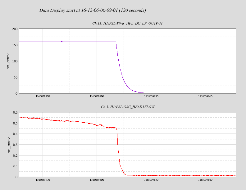
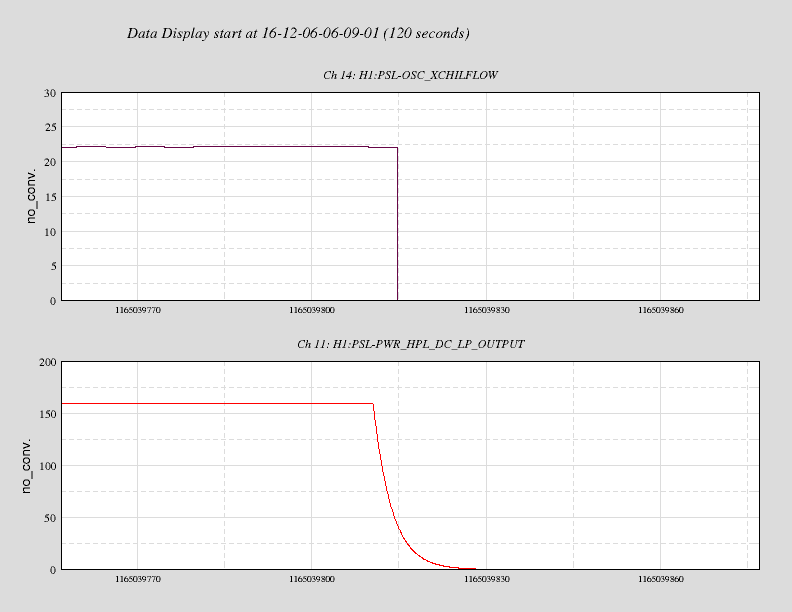
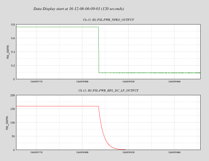
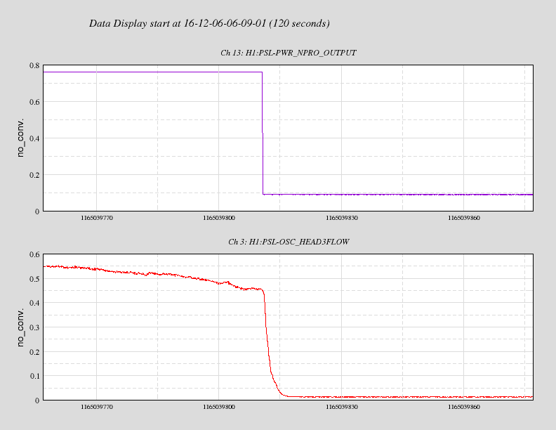
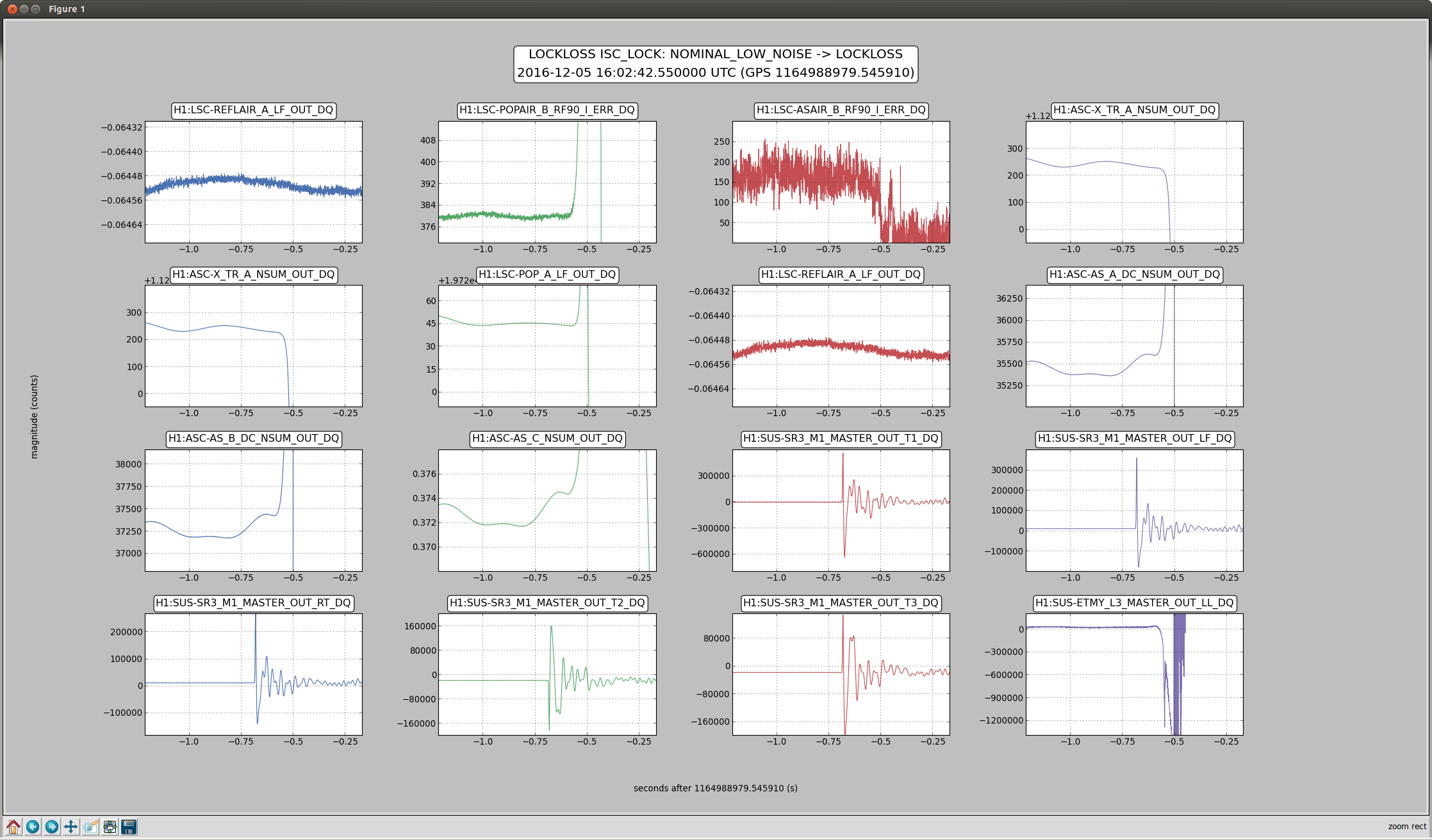
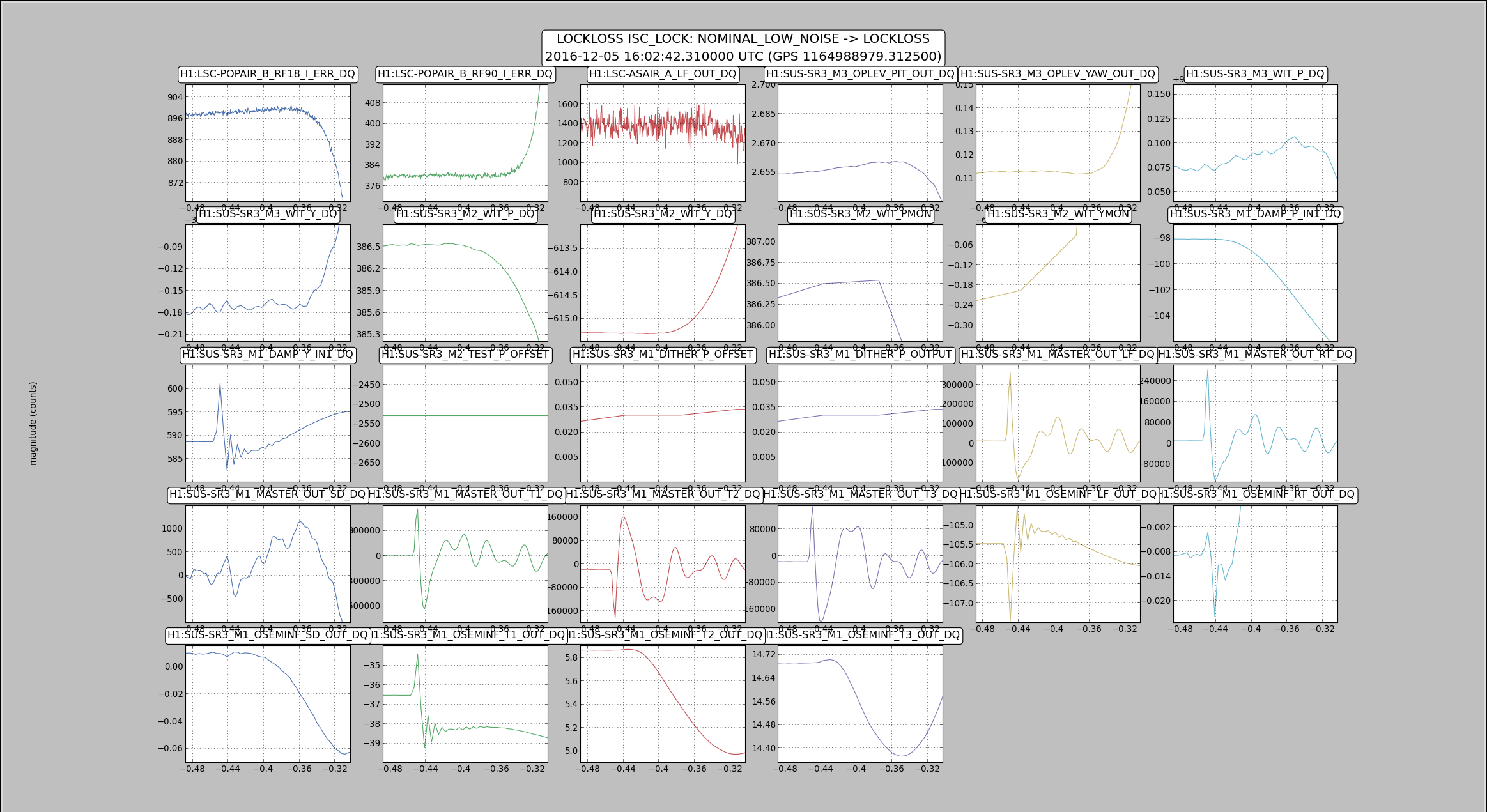
I haven't seen anything of note for the lockloss. I checked the usual templates, with some screenshots of them attached.
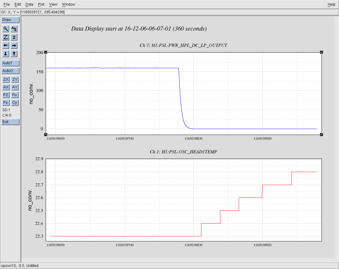
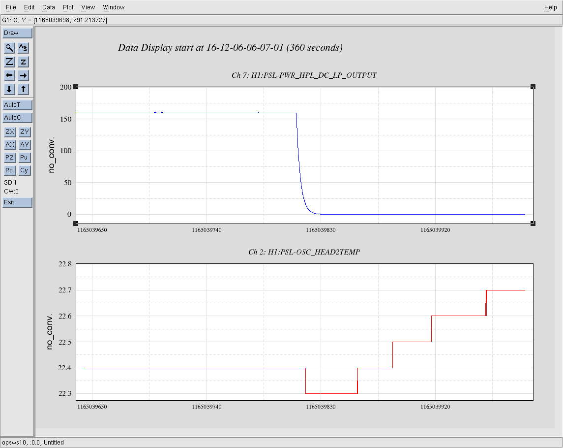
This seems like another example of the SR3 problem. (alog 32220 FRS 6852)
If you want to check for this kind of lockloss, zoom the time axis right around the lockloss time to see if the SR3 sensors change fractions of a second before the lockloss.
See my note in alog 32220, namely that Sheila and I looked again and we see that the glitch is on the T1 and LF coils, which share a line of electronics. The second lockloss TJ started with in this log (12/06) are somewhat unconclusively linked to SR3 - no "glitches" like the first one 12/05, but instead all 6 top mass SR3 OSEMs show motion before lockloss.
Sheila, Betsy
Attached is a ~5 day trend of the SR3 top stage OSEMs. T1 and LF do have an overall step in the min/max of their signals which happened at the time of that lockloss which showed the SR3 glitch (12/05 16:02 UTC)...