Now that we have a few days of O2 under H1's belt. I wanted to give a shout out to the absolute latest Operator Sticky Notes we have so far. And a reminder is that these Sticky Notes are a wiki page here: https://lhocds.ligo-wa.caltech.edu/wiki/OperatorStickyNotes. Some of the older ones have been moved to an "old sticky notes" section at the bottom of the page. Anyone should feel free to update this list to make it pertinent and useful for operations.
Operators please note these latest Sticky Notes:
H1 Sticky Notes & Alogs/Work Permits
-
12/2-12/9: High freq Calib Line Roaming changes (WP#6368)
-
12/1: TCS Power Stabilization Guardian knocking out of Observing (Kiwamu alog#32090)
-
12/1: Surviving rung up resonant modes via "RemoveStageWhitening" (Jenne alog#32089)
-
12/1: ISI_CONFIG during earthquakes (Sheila's comment for alog#32086)
-
12/1: Resonant Mode Scratch Pad! (Jeff's alog #32077)
-
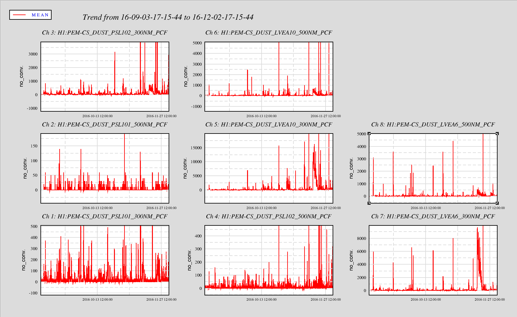
11/30: LVEA SWEPT on 11/29&11/30 by Betsy, Dave, & Fil (alogs 31975, 32024).
-
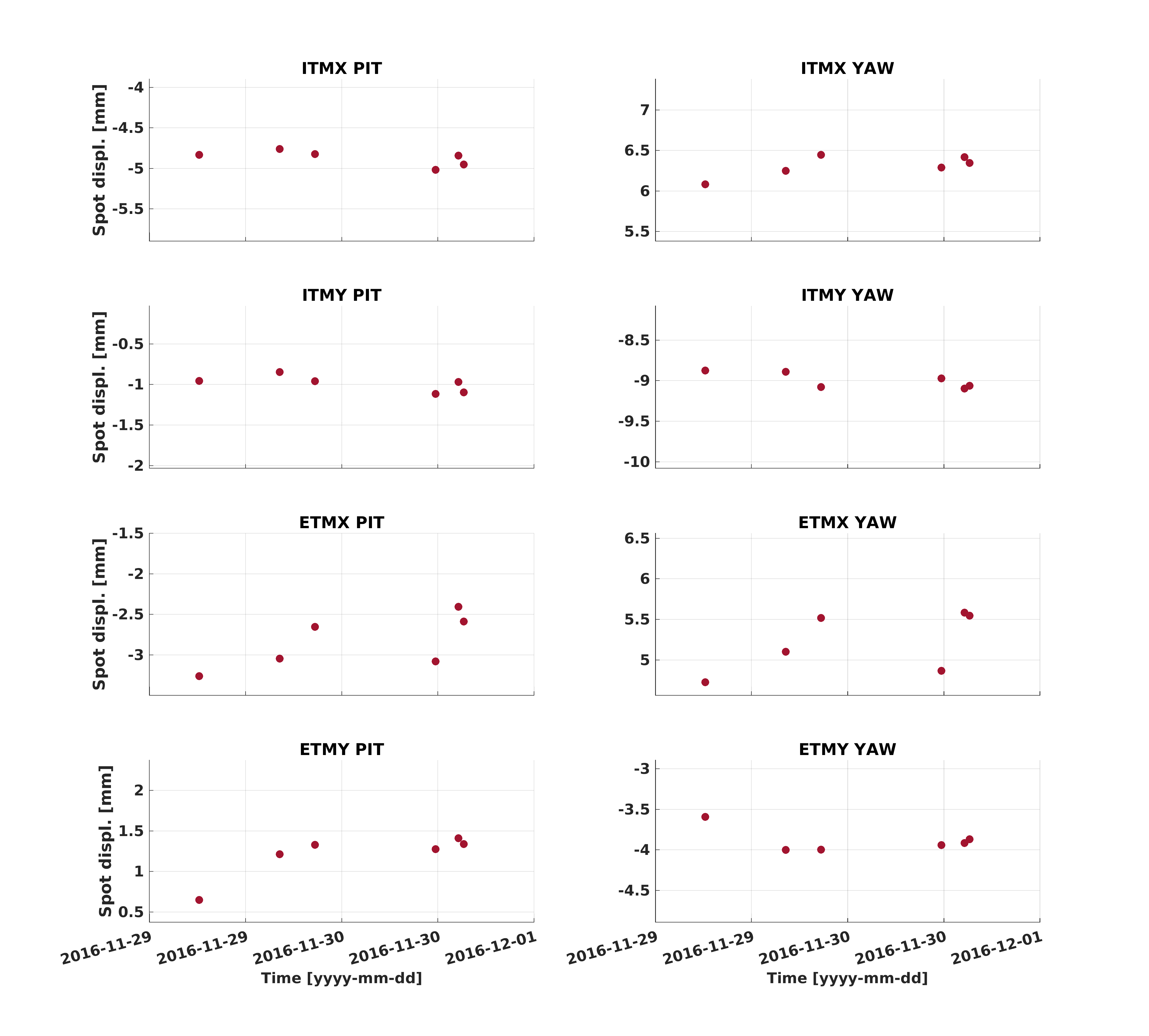
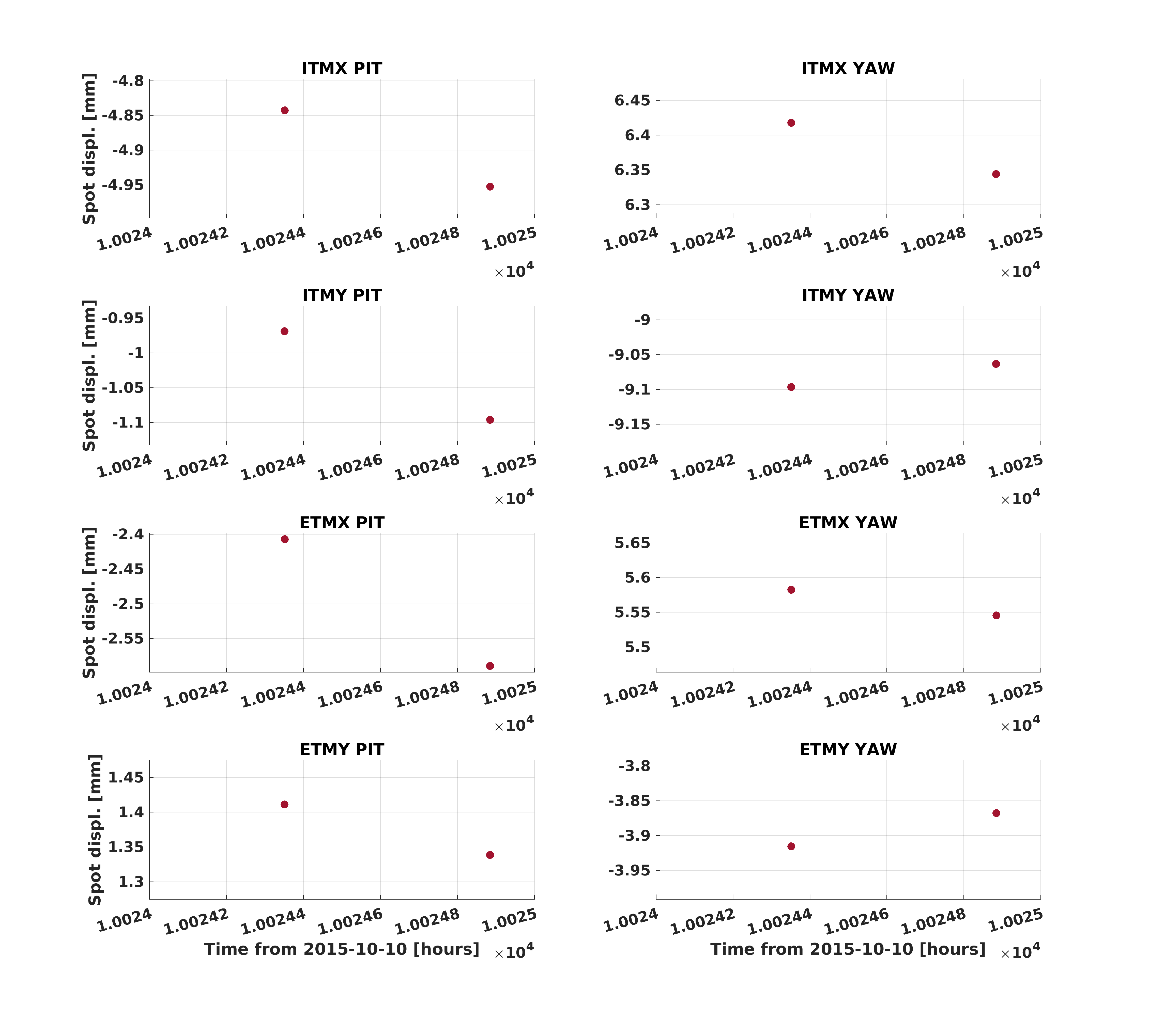
11/30: Run A2L ( once a day until ~12/8. Always run A2L on Tues Maintenance Day. (Jenne alog#32022))


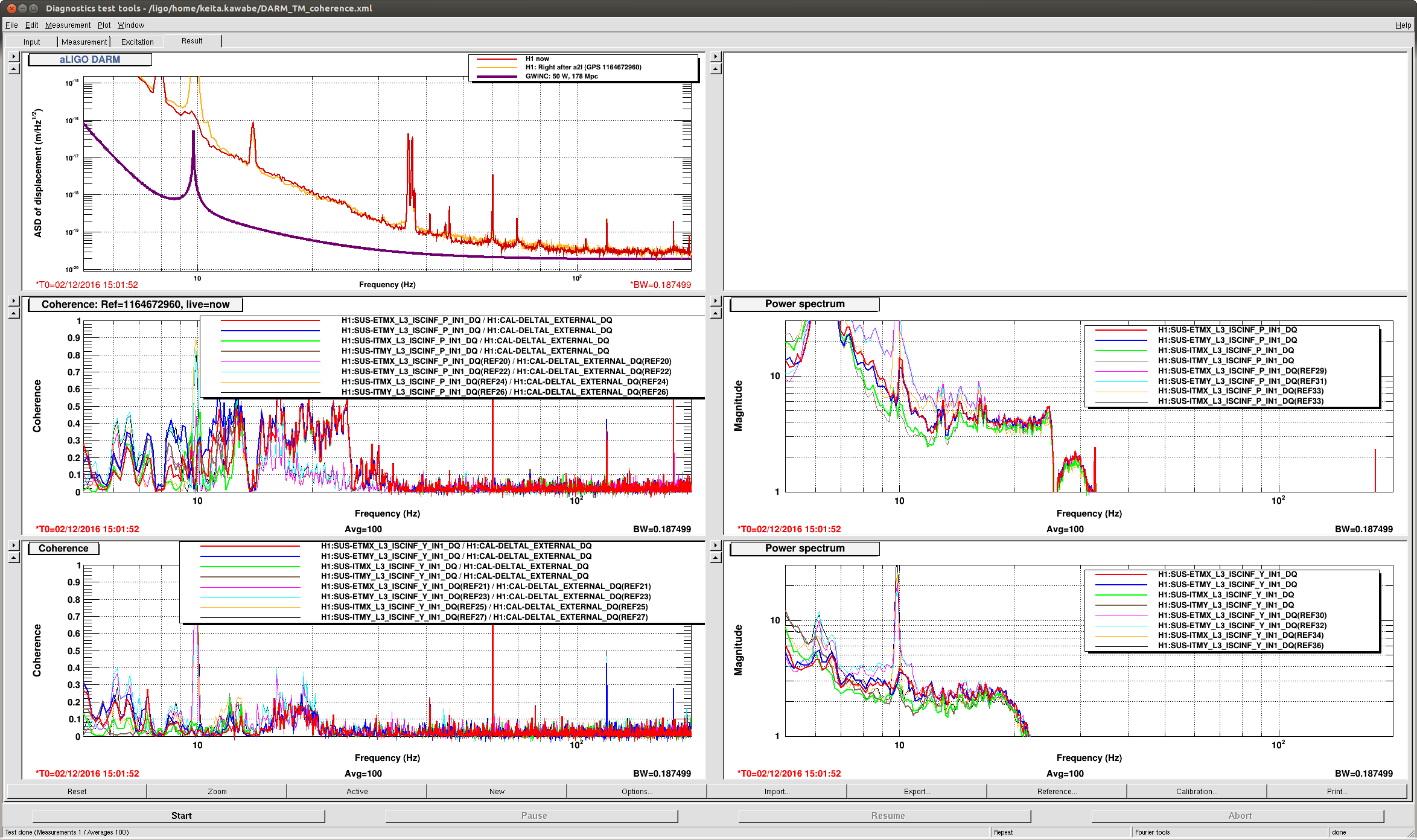
Curious...After reading the aLog about Operator Sticky notes regarding running a2l once a day until 12/8 and running Kiwamu's DTT coherence templates to determine if the script would even be necessaryat this point and asking Patrick if he had run a2l script today (he had not), Keita called 03:15UTC to check on the IFO status. I told him that I had run the DTT measurement and didn't see any loss of coherence in the 20Hz area and asked If I still needed to follow the once-a-day prescription that was aformentioned. He said to me that that plan had changed. If I understood him correctly, only during the first two hours of the lock would it be necessary to run the script if the coherence showed to be out. If this is the case (i'm still not 100% certain) then the Sticky Note needs to be updated and the new plan needs to be disseminated amongst the operators?