corey.gray@LIGO.ORG - posted 09:03, Friday 02 December 2016 (32096)
Ops Day Shift Transition
TITLE: 12/02 Day Shift: 16:00-00:00 UTC (08:00-16:00 PST), all times posted in UTC
STATE of H1: Observing at 73.9893Mpc
OUTGOING OPERATOR: Nutsinee
CURRENT ENVIRONMENT:
Wind: 2mph Gusts, 1mph 5min avg
Primary useism: 0.04 μm/s
Secondary useism: 0.41 μm/s
QUICK SUMMARY:
- Somewhat quiet. The useism has been slowly increasing over the last 10hrs.
- H1's range is hovering around 75Mpc & currently going on a 16.5+hr lock.
- A2L was last run around 16hrs ago (~0:13utc).
-
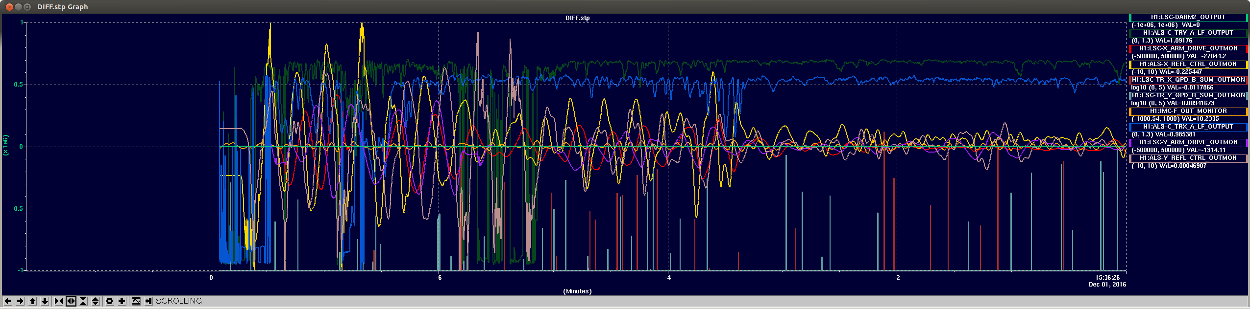
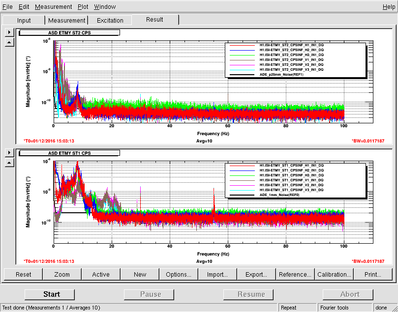
Quick Look at DARM Spectra: Looks good. Only places it's noisy by glancing at it (i.e. where I see reference) are:
- 10-70Hz (perhaps warranting an A2L? Or just happen to see a glitch? Or related to increased usesim.
- A couple bumps between 300-350Hz


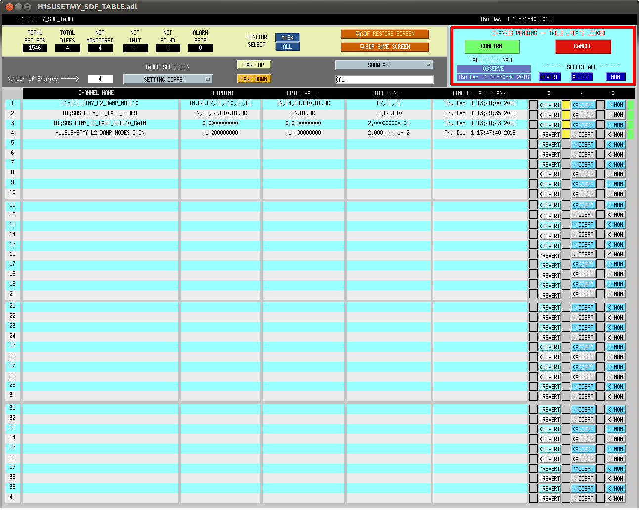

That's excatly what happend. I went and UNmonitored all of the CBRS channels in SDF so this cant happen again.
The rest of the NGN channels are being monitored, but I'm not sure if they should be since they are not tied into the IFO at all. I'll talk to the right people and find out.
Oh, yeah, I'm glad that you not-mon'ed the cBRS channels. Anything in the NGN Newtonian noise model is totally independent of the IFO, and shouldn't be stuff that'll knock us out of observing.
Probably the cBRS and its need for occassional damping is the only thing that will change some settings and knock us out of Observe, so maybe we can leave things as-is for now. The rest of the NGN channels are just seismometers, whos output doesn't go anywhere in the front ends (we collect the data offline, and look at it). Since all of those calibrations are in, and should be fine, I don't anticipate needing to change any other settings in the NGN EPICS channels.