Ops Shift Log: 01/19/2017, Evening Shift 00:00 – 08:00 (16:00 - 00:00) Time - UTC (PT)
State of H1: IFO locked at NOMINAL_LOW_NOISE, power at 28.6W, range at 60.7 Mpc
Intent Bit: Observing
Support: Jenne
Incoming Operator: Patrick
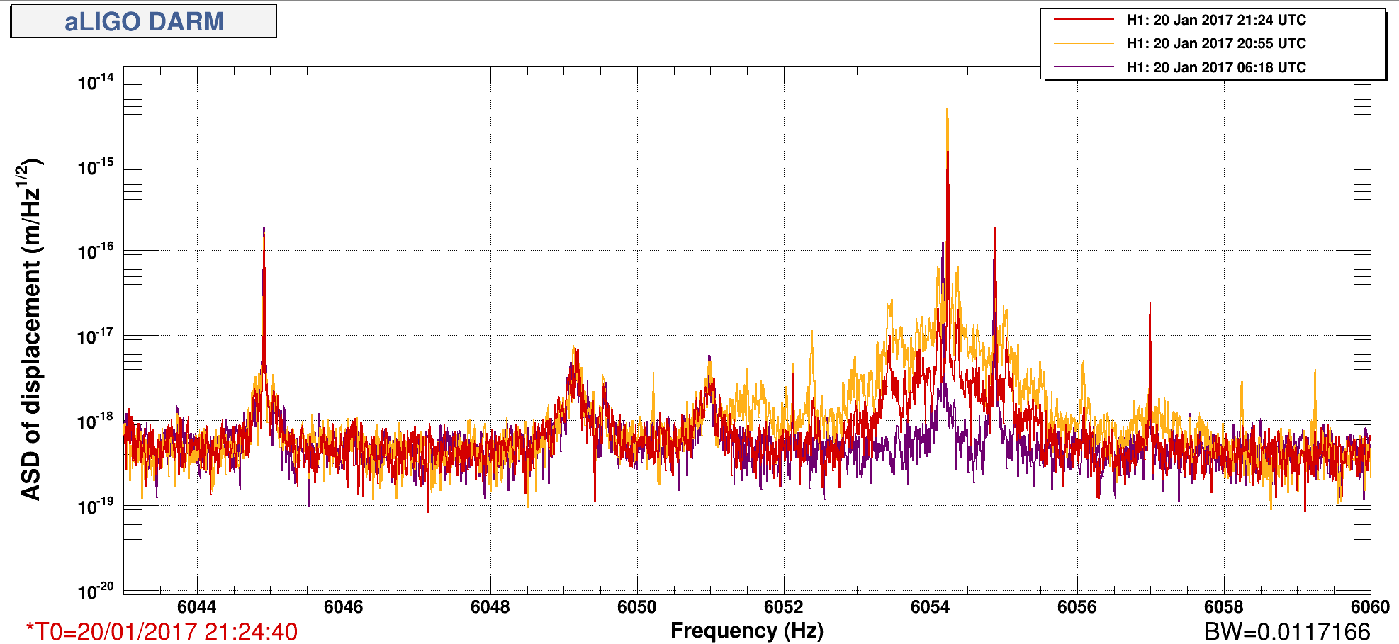
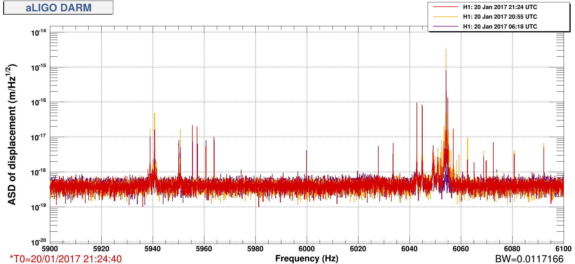
Shift Summary: After seismic settled down from the Solomon Islands EQ, ran initial alignment. Had a bit of problem with Y-Arm green and with SRC_ALIGN. The IFO relocked on the first attempt. The PI Modes 27 & 28 started to ring up shortly after locking. I was able to suppress them at first. Then PI Mode 27 shot up and I could not stop it before the lock was broken. Relocked the IFO after a few attempts. The Observing bit has been set for the past 4 hours.
The A2L DTT script shows the yaw component has been elevated all shift. LLO and LHO were locked the same time all night, so there has not been a good time to run the script.
Patrick reports the roads are OK but the fog is thick.
Activity Log: Time - UTC (PT)
00:00 (16:00) Take over from TJ
00:01 (16:01) Robert – Down to End-Y to reset BRS STS
00:41 (16:41) Kyle – To Mid-X for vacuum checks
00:56 (16:56) Robert – Back from End-Y
00:59 (16:59 Kyle – Back from Mid-X
01:41 (17:41) After seismic calmed down from the earlier EQ - Ran Initial Alignment
02:07 (18:07) IFO relocked on first try
02:22 (18:22) Suppress PI Mode 27
02:23 (18:23) Robert – LLO is down so doing injection (WP #6440)
02:32 (18:32) Run A2L Passive script - The Y component is a bit elevated
02:36 (18:36) Suppress PI Mode 28
02:40 (18:40) Suppress PI Mode 27
02:45 (18:45) Suppress PI Mode 28
02:48 (18:48) Robert – Finished with injections
02:50(18:50) Try to suppress PI Mode 27
02:51 (18:51) Lockloss – Due to PI Mode 27 which did not respond to attempts to suppress
03:46 (19:46) Relocked at NOMINAL_LOW_NOISE
03:47 (20:47) Set the intent bit to Observing
04:16 (21:16) Suppress PI Mode 27
08:00 (00:00) Turn over to Patrick


It would be good to know if we should keep these Readers OFF or ON. Originally we had been turning them OFF after LVEA Sweeps, but the Sweep checklist had this crossed out & it marked with "ON" (So, the most recent version of the Checklist had the Card Reader line removed).
Maybe these Card Readers are not an issue? Maybe I heard Robert say these Card Readers were negligible.
Robert Schofield's investigations showed no coupling from the card reader in O1. These should be left ON, as they are used by the RRT for site status reconstruction in trigger evaluation.