thomas.shaffer@LIGO.ORG - posted 10:15, Tuesday 17 January 2017 - last comment - 10:16, Tuesday 17 January 2017(33374)
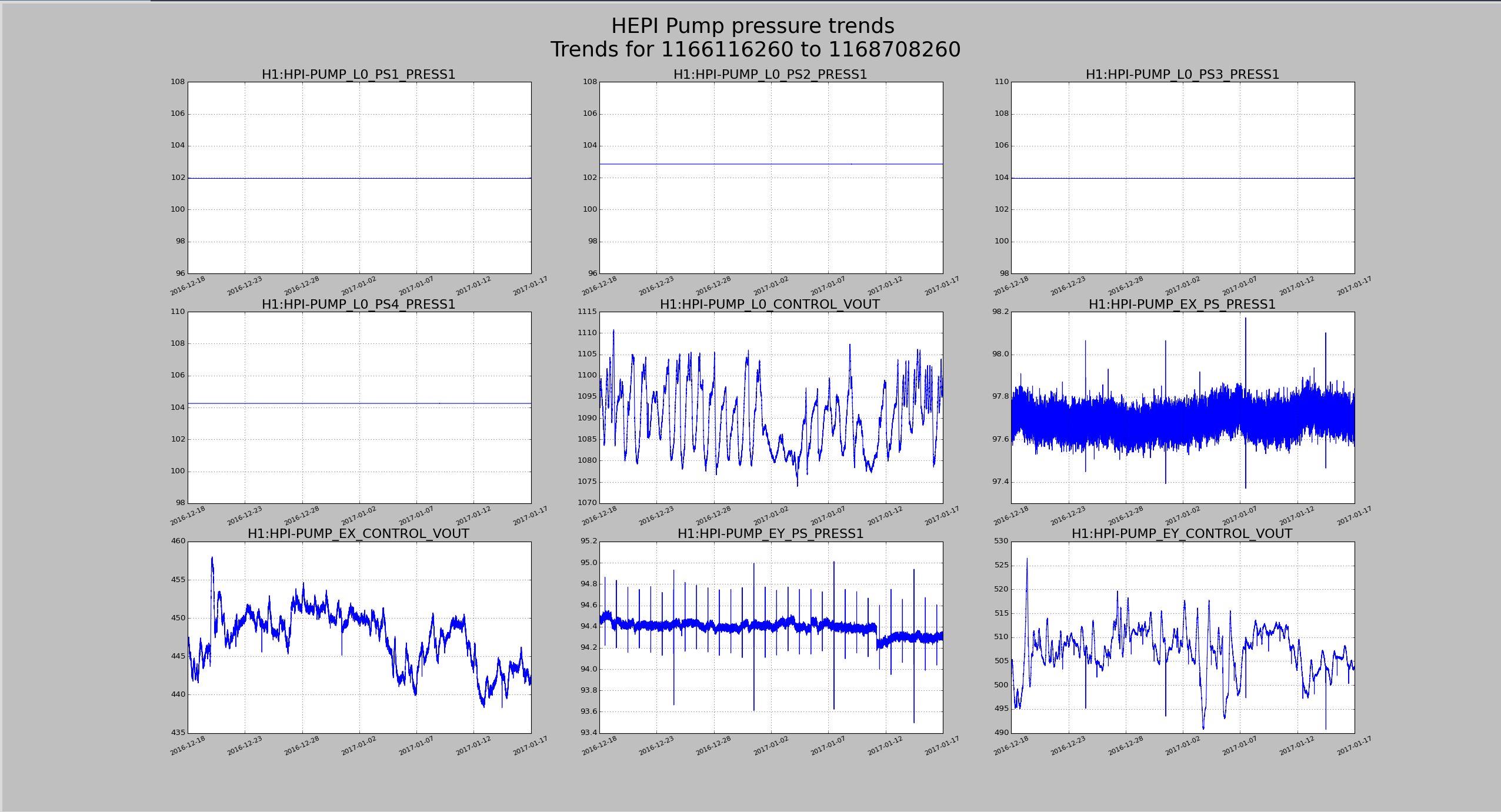
HEPI Pump Pressure 45 Day Trends
EY Pressure looks like it dropped a tiny bit on 1-11-2017, but I don't see any other issues.
Images attached to this report
Comments related to this report
This closes FAMIS4528.
