cheryl.vorvick@LIGO.ORG - posted 00:20, Sunday 22 January 2017 (33498)
Ops Eve Summary
- recovery from EQ
- SEI is back
- IMC is back
- IMs realigned to Nominal
- handing off to Patrick
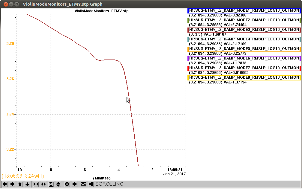
Plot attached shows the mode damping much faster after I engaged the -60 deg phase filter. I had increased the gain (-20 to -50) before the phase change with no positive results to damping, which led me to trying a phase change. Doubt I'll get far enough to try again and confirm in a second lock (M8.0 earthquake).
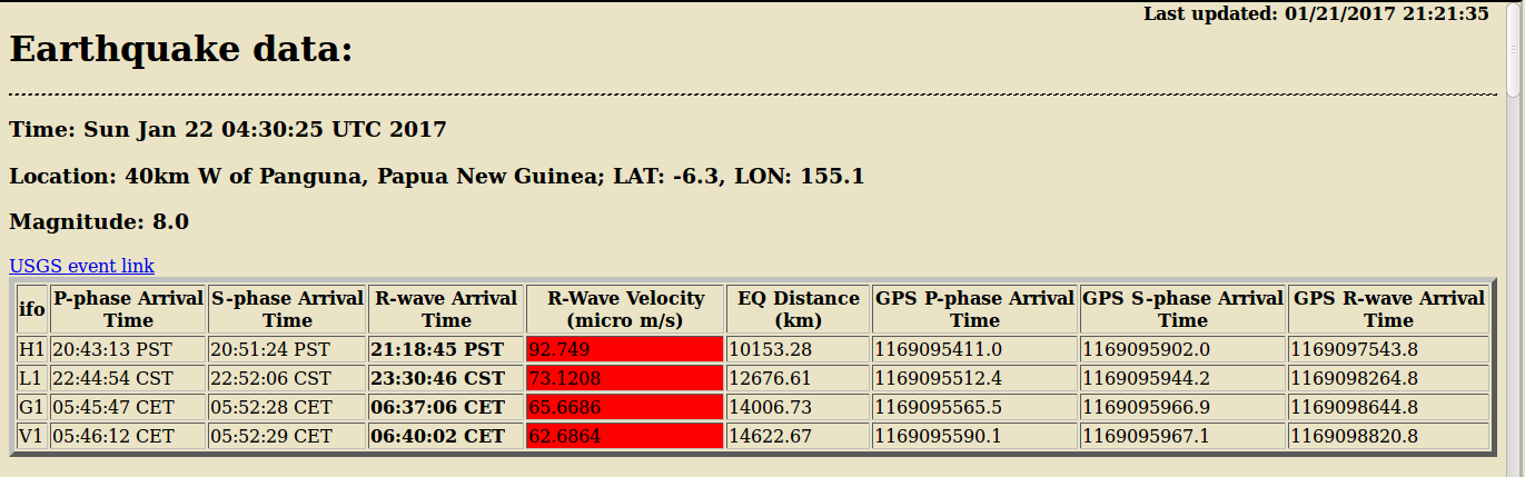
Terramon:
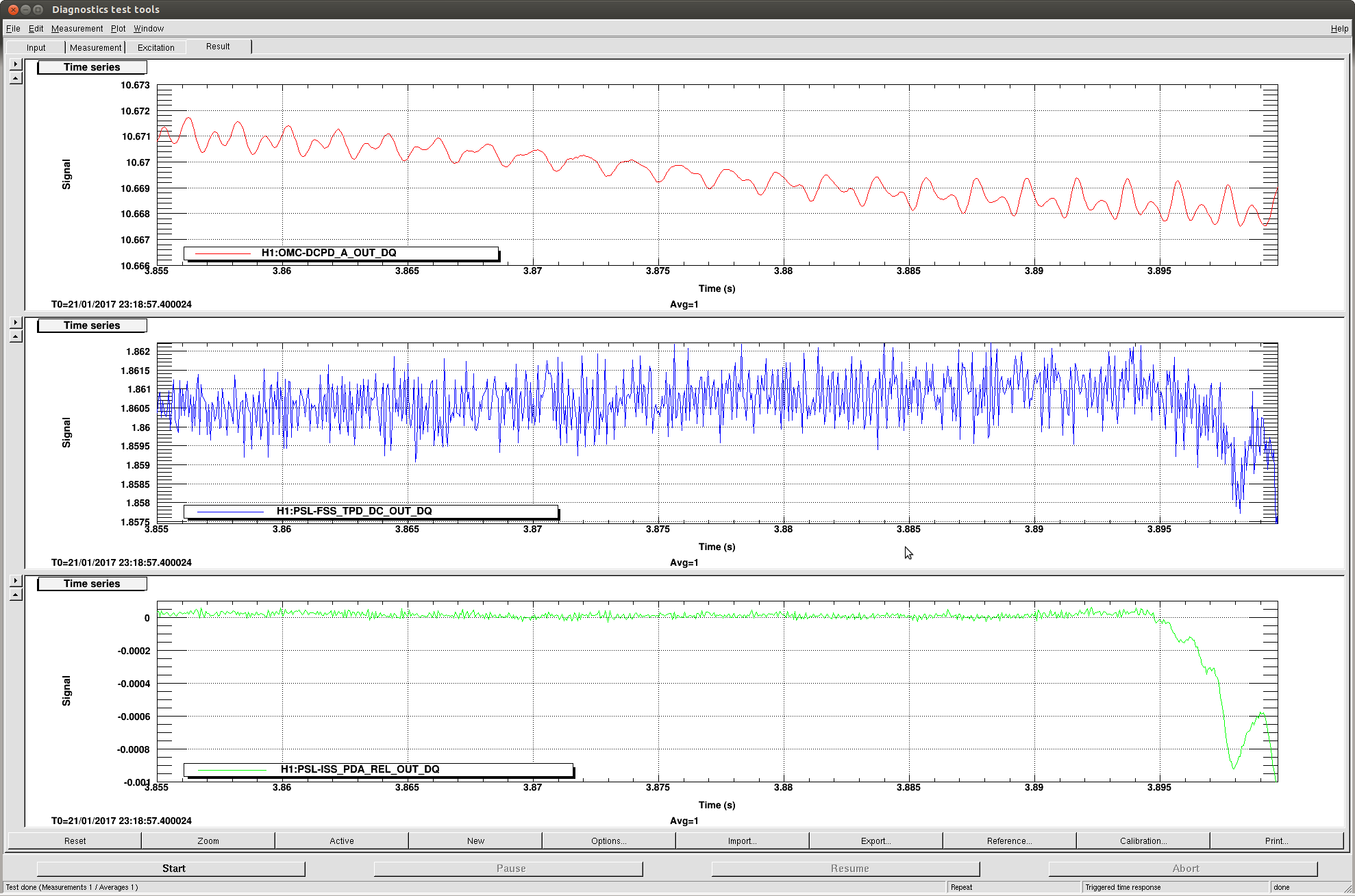
Attached is a plot that shows the FSS_TPD_DC has a small drop in power right before lockloss at 23:19UTC (jan21).
The ISS_PDA_REL_OUT also drops, though I don't know what the power is relative to. The amplitude of the signal is about 0.0001 before the power drop, and the power drops by 0.001 (10x amplitude) before lock loss.
If this lockloss is the Noise Eatter going from OK to Not OK, while H1 is locked locked, it won't be for long, so a Verbal Alarm / DIAG_MAIN notice wouldn't help Operators.
Having a Verbal Alarm / DIAG_MAIN notice on the Noise Eatter would allert Operators to the Noise Eatter issue after lock loss, which I think would be helpful.
TITLE: 01/22 Eve Shift: 00:00-08:00 UTC (16:00-00:00 PST), all times posted in UTC
STATE of H1: Observing at 64Mpc
OUTGOING OPERATOR: Jim
CURRENT ENVIRONMENT:
Wind: 3mph Gusts, 1mph 5min avg
Primary useism: 0.08 μm/s
Secondary useism: 0.87 μm/s
QUICK SUMMARY:
TITLE: 01/21 Day Shift: 16:00-00:00 UTC (08:00-16:00 PST), all times posted in UTC
STATE of H1: Observing at 65Mpc
INCOMING OPERATOR: Cheryl
SHIFT SUMMARY:
Little frustrating day with and IMC which had an alignment shift and then another lockloss due to ISS saturations. Other than that, we are battling large useism.
LOG:
At 23:19, H1 had a lockloss (which was unfortunate because it was starting to ramp up in range!). There were no seismic event,
BUT....
IMC was not relocking. No other alarms, so delved into PSL's ISS, and found a couple of issues
1) ISS Was Saturating
Did not really know to go here other than I rememeber having a Diff for the ISS for last lock. And sure enough, I saw the ISS not looking healthy. Eventually called Jason and told him the....
SYMPTOMS: Diffracted Power racing up to 12% & seconds later it would drop. It kept on cycling like this.
Jason told me...
THE FIX:
2) NOISE EATER OFF
When Cheryl arrived she happened to notice that the NOISE EATER was OFF! (She also found it went off when the OMC broke lock during the lockloss...so maybe this was the cause of the lockloss?). I went out and turned it on for Cheryl and she relocked the FSS and is now back to locking.
Note: I did go to a CORRECTIVE MAINTENANCE Observatory Mode for a few minutes while we were down.
No obvious seismic jolt for lockloss, BUT we had been riding some high useism.
Locking Notes:
1) IMC not locking! (it did look misaligned on Trans when it tried grabbing lock)
2) H1 Locking Status: Have had a couple of failed attempts after & before CARM Reduction steps.
Have had a few more DRMI locklosses drop before the CARM steps & earlier.
Going to try an Initial_Alignment and see if this changes any results here. If not, will return to investigation of steps before CARM REDUCTION.
Mode Cleaner continues to be a pain.
This is my third instance of needing to Clear Histories. (mainly the Pitch outputs were high).
Going back to Initial Alignment.
When you get it re-locked, try letting it be for about 15-20 minutes to give the loops time to optimize the alignment, maybe. That's what I do.
18:23 - 21:23 Out for Locking & Alignment (during high useism)
Assuming the lockloss could be related to our high useism (no jolts seen on any of our BLRMS seis bands).
Tried to do what I could to get it back up w/o a full Initial Alignment (by tweaking MCs to get IMC back & then usual BS/PRM), but after several locklosses after DRMI, I opted to give an Alignment.
After the alignment, dropped a handful of times, but went step by step in Guardian and finally got through the CARM reduction steps (I never got to a point where I needed to run Guardian line by line...talking with Jim we just wanted to get it through the CARM steps in this high useism). At any rate, finally made it past the CARM reduction steps and up to NOMINAL_LOW_NOISE!
Did notice a few SDF Diffs that I ACCEPTED:
Ed: What step were you suggesting I should have paused?
The IMC was a bit frustrating through all of this. Have not had to be so hands-on to it in my experience over last few months.
Currently running at 66Mpc. and can certainly useism oscilltion on LSC signals on Strip Tools, the Tidal StripTool, and even PI Mode28.
Crystal Chiller topped off with 265mL this morning (Diode Chiller had GREEN light for its level). This closes FAMIS 6506.
TITLE: 01/21 Day Shift: 16:00-00:00 UTC (08:00-16:00 PST), all times posted in UTC
STATE of H1: Observing at 63Mpc
OUTGOING OPERATOR: Patrick
CURRENT ENVIRONMENT:
Wind: 5mph Gusts, 4mph 5min avg
Primary useism: 0.19 μm/s
Secondary useism: 0.87 μm/s
QUICK SUMMARY:
Not much to hand-off from Patrick other than the Configuration Change note for H1OAF on the CDS Overview.
useism has inched up in the last 8-10hrs (above the 90percentile and almost clearing it!) & you can see the signal on the Tidal Striptool (nuc1).
Beautiful clear morning with no issues driving in & a crisp 28degF out.
TITLE: 01/21 Owl Shift: 08:00-16:00 UTC (00:00-08:00 PST), all times posted in UTC
STATE of H1: Observing at 65Mpc
INCOMING OPERATOR: Jim
SHIFT SUMMARY: Remained in observing the entire shift. The filter changed by Sheila that Cheryl reported in her shift summary remains unloaded.
LOG:

09:14 UTC Damped PI mode 28 by changing sign of gain
14:45 UTC GRB alert
Background -
Both CP3 and CP4 are experiencing obstructed "high side" sensing lines which prevent their level transducers from measuring the level of LN2 in the 80K pumps.  We consider that this is due to accumulated ice at the bottom of the pumps inner LN2 vessel where the "high side" sensing line transitions from the relatively large ID aluminum tube to the relatively small ID stainless tube near a 90 degree elbow.  While Chandra R. has developed a procedure for a permanent post-O2 fix, we, nevertheless, would like to pursue more accommodating fix attempts in the meantime.  One of these is to see if by applying a vacuum (for a prolonged period) to the sensing line enough ice could be liberated through reverse sublimation that the obstruction could then be freed by alternating applications of modestly pressurized UHP N2 followed by vacuum pumping.

Today -
WP #6442
Kyle R., Chandra R., Dave B., Gerardo M., Marc P.
I reconnected the "clogged" sensing line (with added parallel valved line used for vacuum pumping and a parallel valved line used for back filling) to the CDS level transducer (Rosemont model 1151DP4E52B404).  I then applied various "on-scale" pressure differentials via the back fill line (as indicated by the parallel connected magnahelic DP gauge) while Chandra R., Dave B. and Gerardo M. monitored the CDS MEDM screen. This confirmed that the transducer was operating and was in rough agreement with the mechanical gauge.  I also switched to the application of vacuum and they noted that the 4-20ma transducer output fell to 0 mA or something less than 4 mA (thought 4 mA output was minimum output?).  I then rearranged the plumbing fittings so as to permit selecting between a vacuum pump or a back fill line (10 psi UHP N2 @ 2 LPM) without the need to undo any tubing fittings as had been the case initially.  During this plumbing rearrangement, the sensing line was open to the room and began to flow GN2 past the obstruction.  This phenomenon had been observed on previous dislodge attempts (see entries from last month?) the difference this time was the significant increase in volume and duration - "Almost got it!"  I experimented with various durations of pumping and back filling etc. and observed on a few occasions that the audible gas load to the diaphragm pump would change spontaneously if let alone for several minutes.

Anyway, this is all very encouraging and will likely be continued next week.  I halted tonight's attempts in observance of the Vacuum Team's Friday Rule and to allow others (the larger vacuum community) to consider if this approach is thermally cycling the bi-braze joint and poses a risk.  I am leaving the sensing line back filled to 10 psi and isolated from both the vacuum line and back fill line.
Uh...make that sublimation or reverse deposition