J. Kissel
I'm building up some controls design documentation for the derivations of the OSEM2EUL / EUL2OSEM matrices for existing suspension types (see G2402388), in prep for deriving new ones for e.g. the HRTS and if we upgrade any SUS to use the 2-DOF AuSEMs.
In doing so, I re-remembered that the HLTS, HSTS, OMC controls arrangement poster (E1100109), defining the now-called "6HT" OSEM arrangement in T2400265 calls out two possible positions for the transverse sensor, the "side" and "opposite side," which I'll abbreviate as SD and OS, respectively from here on.
If the transverse sensor is mounted in the SD position, then as the suspension moves in +T, the OSEM further occults the LED beam, creating a more negative ADC signal. Thus, the OSEM2EUL matrix's SD to T element should be -1.0.
If the transverse sensor is mounted in the OS position, then as the suspension moves in +T, the OSEM opens up revealing more LED beam, creating a more positive ADC signal. Thus, the OSEM2EUL matrix's SD to T element should be +1.0.
Not *actually* remembering that the HLTSs PR3, SR3, and two of the 9 HSTSs, SR2 and SRM use OS as their transverse sensor yesterday, and missing the note from Betsy in the abstract of E1100109 to look at the each SUS' Systems Level SolidWorks assembly for transverse sensor location assignment (prior to this morning it was not in red, nor did it call which suspension explicitly have their transverse sensor mounted in the OS position), I was worried that we'd missed this when defining the sign of *all* HLTS / HSTS / OMCS OSEM2EUL / EUL2OSEM matrices, and assumed they were all installed as SD OSEMs with -1.0 OSEM2EUL and EUL2OSEM matrix elements.
Below, I inventory the status with
- suspension name,
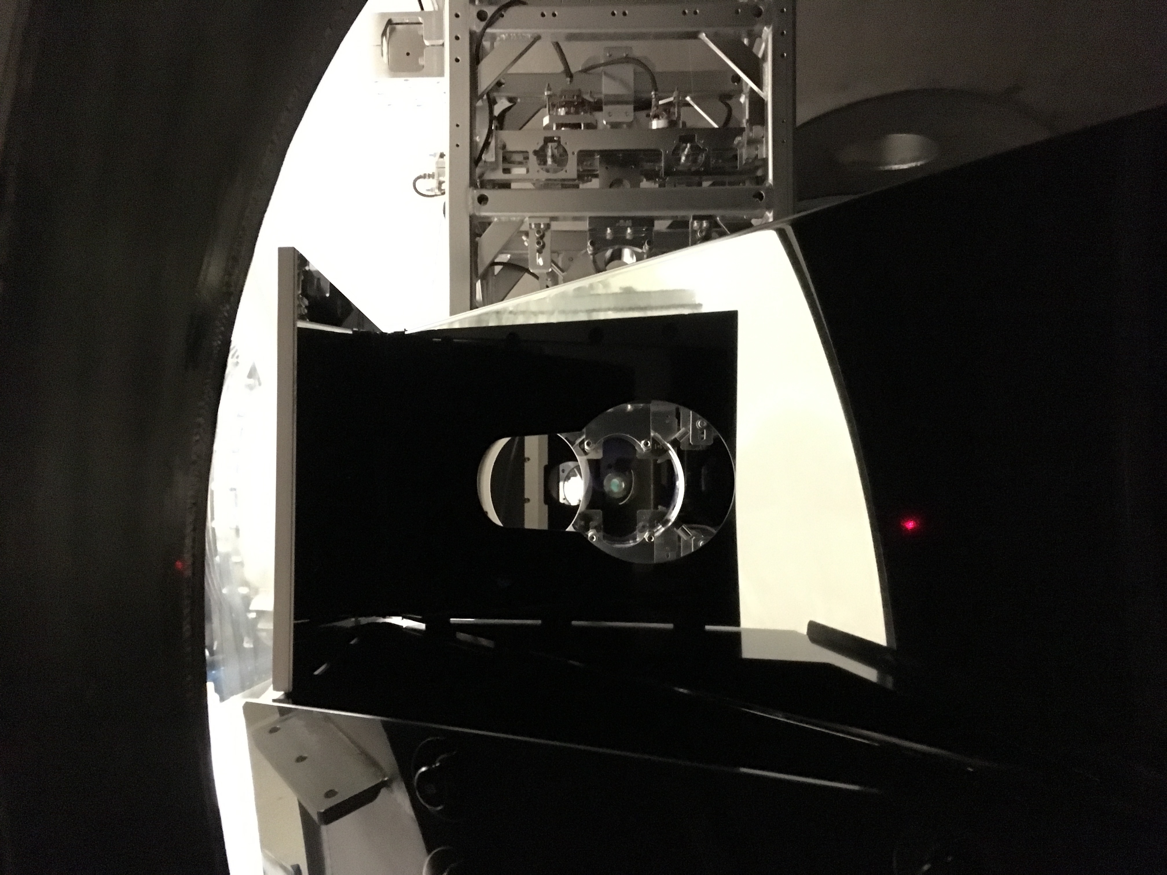
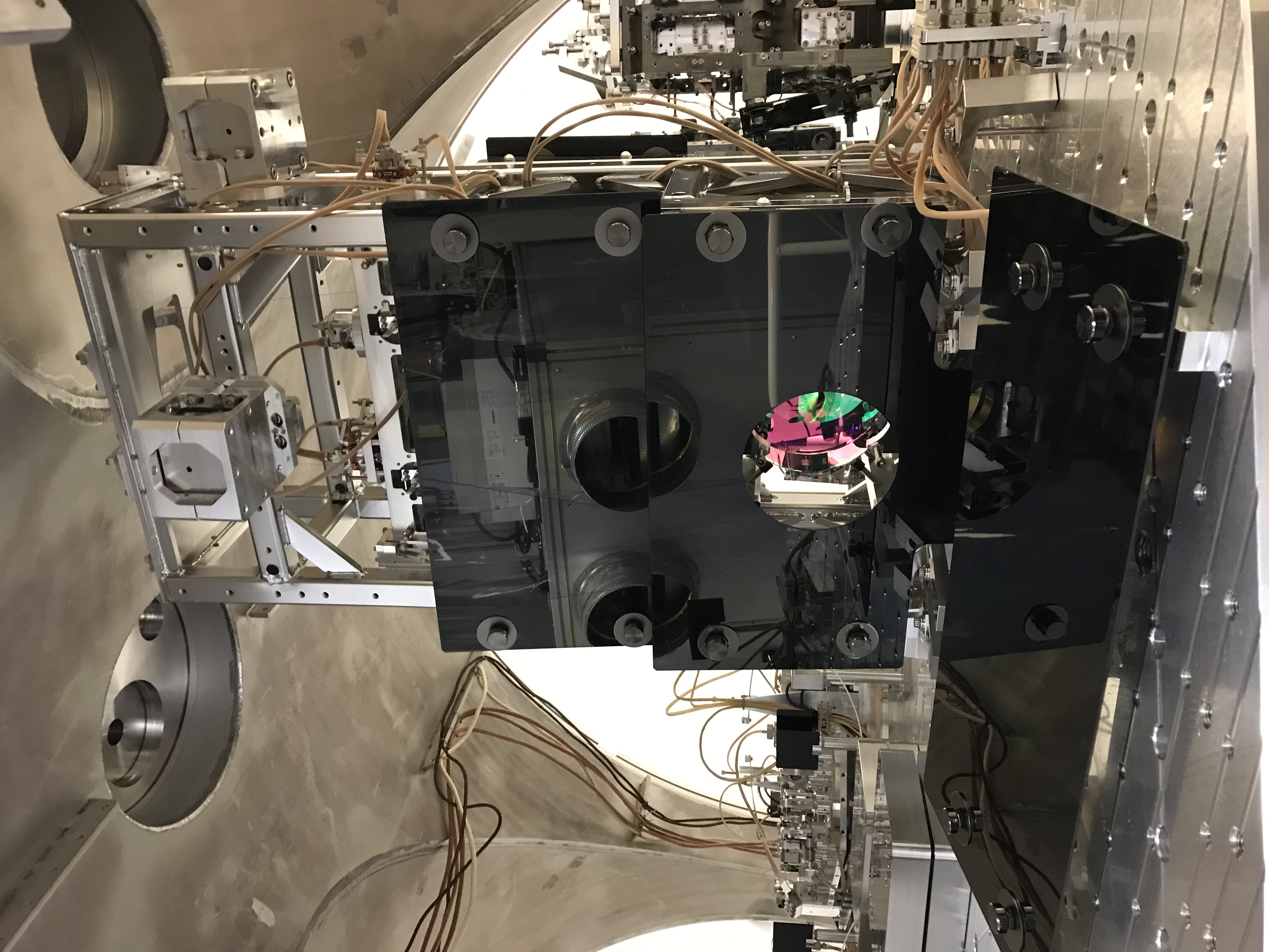
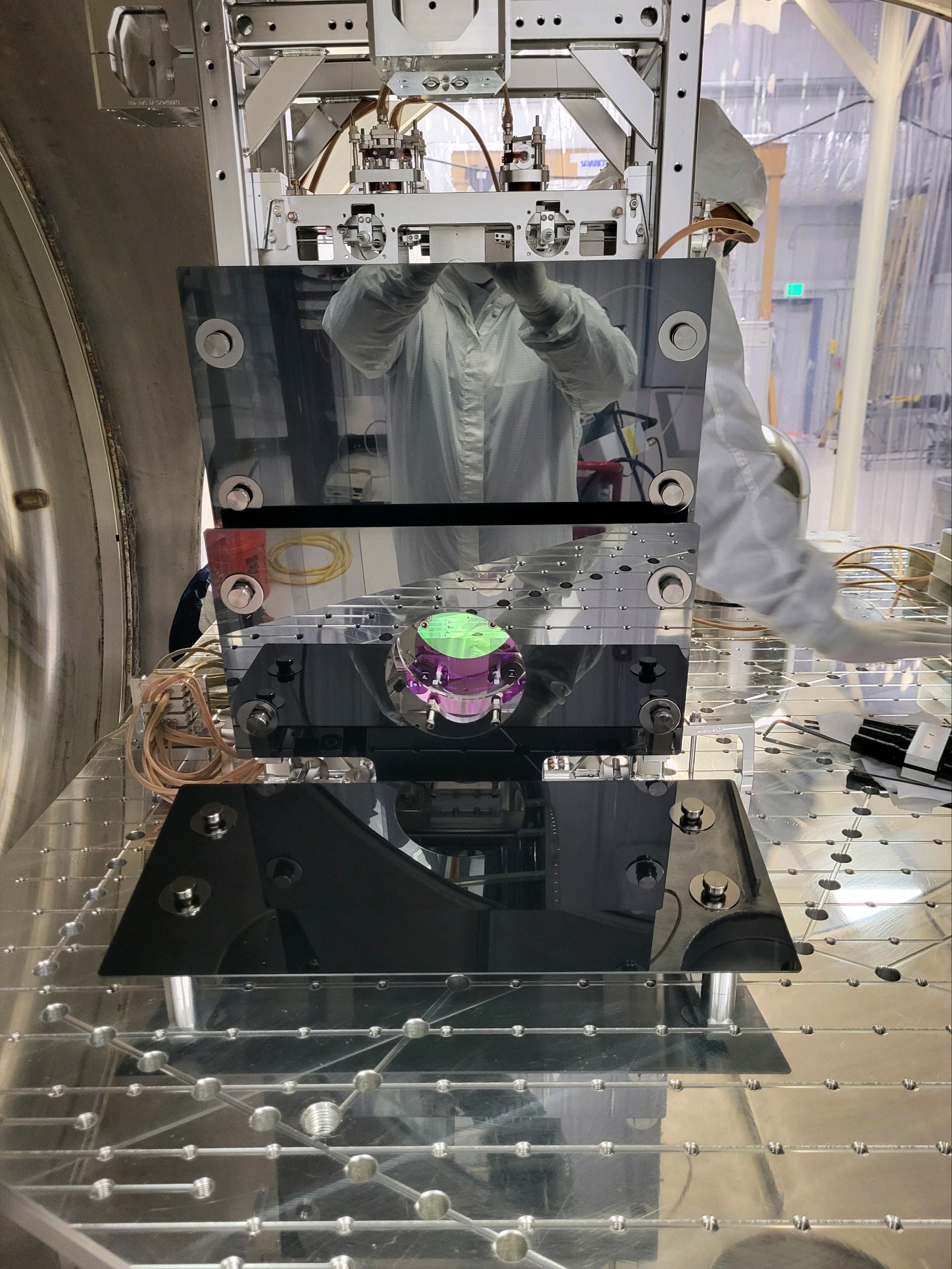
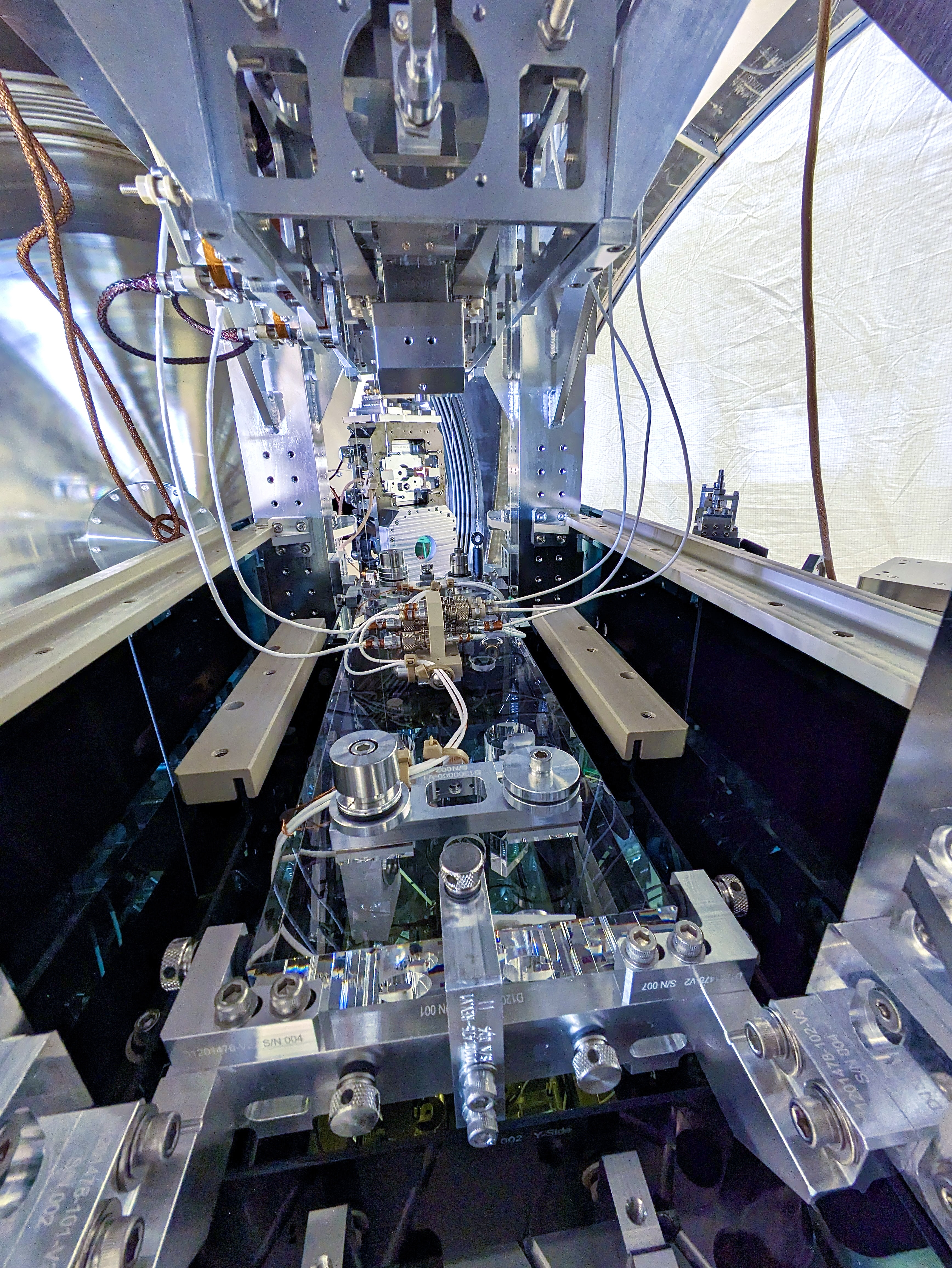
- a reference to picture of the transverse OSEM (or the corresponding flag w/o the OSEM),
- confirming SW drawing does match the picture,
- the current value / sign of the OSEM2EUL / EUL2OSEM matrix element (H1:SUS-${OPTIC}_M1_OSEM2EUL_2_6 or H1:SUS-${OPTIC}_M1_EUL2OSEM_6_2)
- a conclusion of "all good" or what's wrong.
Optic T Sensor aLOG pic SW check OSEM2EUL Conclusion
Mount value /EUL2OSEM
MC1 SD LHO:6014 D0901088 g -1.0 all good
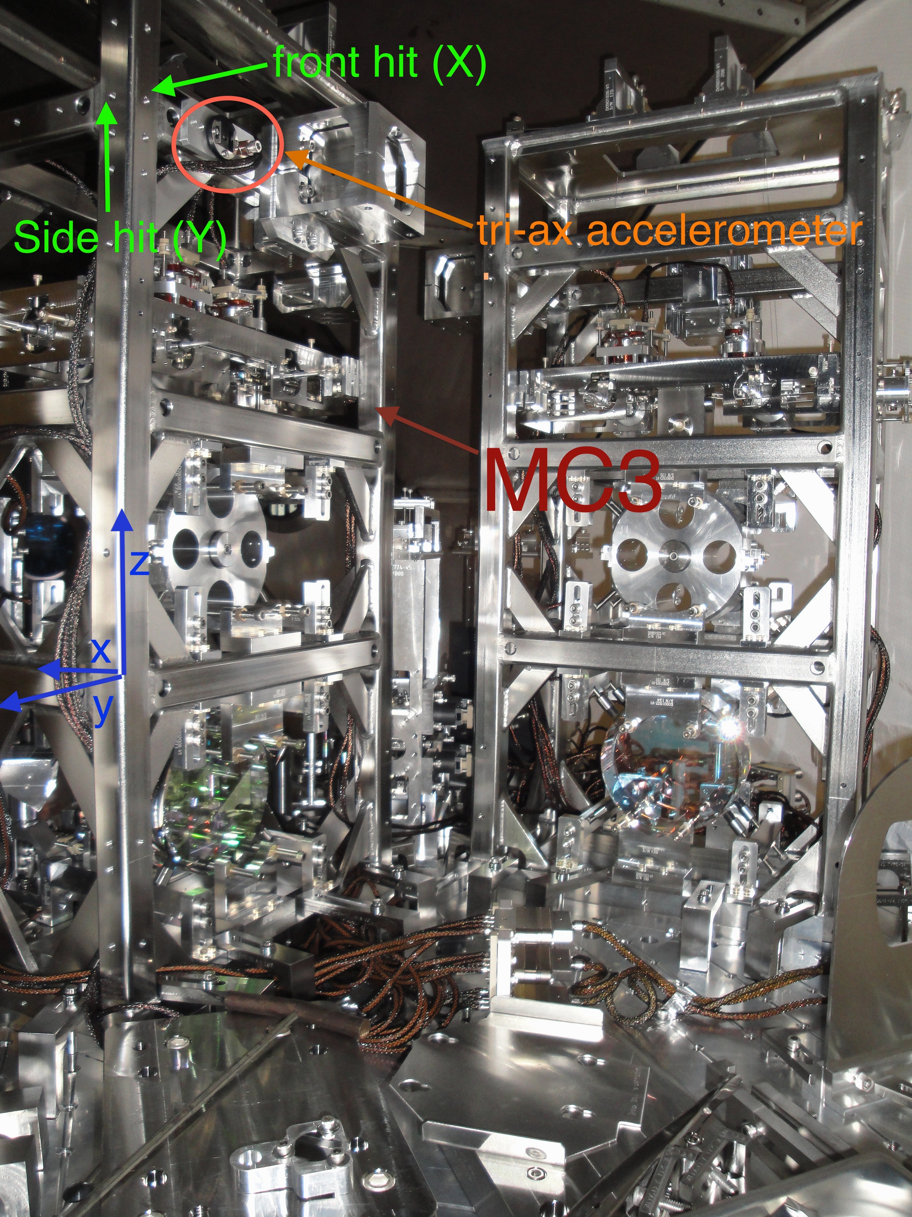
MC3 SD LHO:39098 D0901089 g -1.0 all good
PRM SD LHO:39682 D0901090 g -1.0 all good
PR3 OS LHO:39682 D0901086 g +1.0 all good
MC2 SD LHO:85195 D0901099 g -1.0 all good
PR2 SD LHO:85195 D0901098 g -1.0 all good
SR2 OS LHO:41768 D0901128 g +1.0 all good
SRM OS LHO:60515 D0901133 g -1.0 OSEM2EUL/EUL2OSEM wrong!
SR3 OS LHO:60515 D0901132 g +1.0 all good
FC1 SD LHO:61710 D1900364 g -1.0 all good
FC2 SD LHO:65530 D1900368 g -1.0 all good
OMC SD LHO:75529 D1300240 g -1.0 all good (see also G1300086)
So, as the title of this aLOG states, we've got the sign wrong on SRM.
Shouldn't we have discovered this with the "health check TFs?"
Why doesn't this show as a difference in the "plant" ("health check") transfer functions when comparing against other SUS that have the sign right?
Why *don't* we need a different sign on SRM's transverse damping loop?
Because the sign in the EUL2OSEM drive and OSEM2EUL sensed motion is self consistent:
When SRM EUL2OSEM matrix requests to drive in +T as though it had an OSEM coil in the "SD" position, it's actually driving in -T because the OSEM coil is in the OS position.
On the other side, the OSEM2EUL matrix corrects for a "SD" OSEM, with "more negative when moves in +T", and and has the (incorrect) -1.0 in the OSEM2EUL matrix. But since the SUS is actually moving in -T, making the flag occult more of the OS OSEM LED beam, yielding a more negative ADC signal, the -T is reported +T in the DAMP bank because of minus sign in "SD" OSEM2EUL matrix.
So the phase between DAMP OUT and DAMP IN at DC is still zero, as though "everything was normal," because requested physical drive +T is sensed as +T.
Thus the Sensor / Drive phase is zero at DC like every other HSTS, we can use the same feedback -1.0 sign like every other DOF and every other HSTS.
Does this matter for the IFO?
No. This sensor is only used to damp transverse, i.e. transverse to the main IFO beam. If there're no defects on the SRM optic HR surface, and the transverse displacement doesn't span a large fraction of the beam width, then there should be no coupling into L, P or Y which are the DOFs to which the IFO should be sensitive.
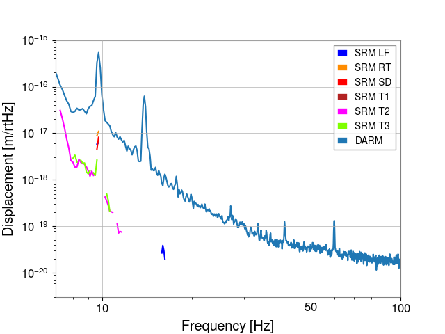
This is corroborated by Josh recent work where he measured the coupling of the "SD" OSEM drive (actually in the OS position, driving -T) and found it to be negligible; see LHO:83277, specifically this SRM plot.
Not only is the IFO not sensitive to the transverse drive from the OSEM, but also the absolute sign of whether it's +T or -T doesn't matter since there's no *other* sensors that measure this DOF that we'd have to worry about comparing signs against.
Should we fix it?
I vote yes, but with a low priority, perhaps during maintenance when we have the time to gather a "post transverse sensor sign change fix" set of transfer functions.

