Have started getting this verbal alarm. For first one I went to check TCSy Chiller and topped it off.
But after getting more alarms, I went to check again and it was still full.
Looking at Chiller screen, can see that the Flow Rate is RED & attached is a trend of the last 6-hrs. Looks like there was a step down in flow rate. It might be coming back up slowly.....
(I'm also not very familiar with how the TCSy Laser works. Does it turn on/off normally during locks?)
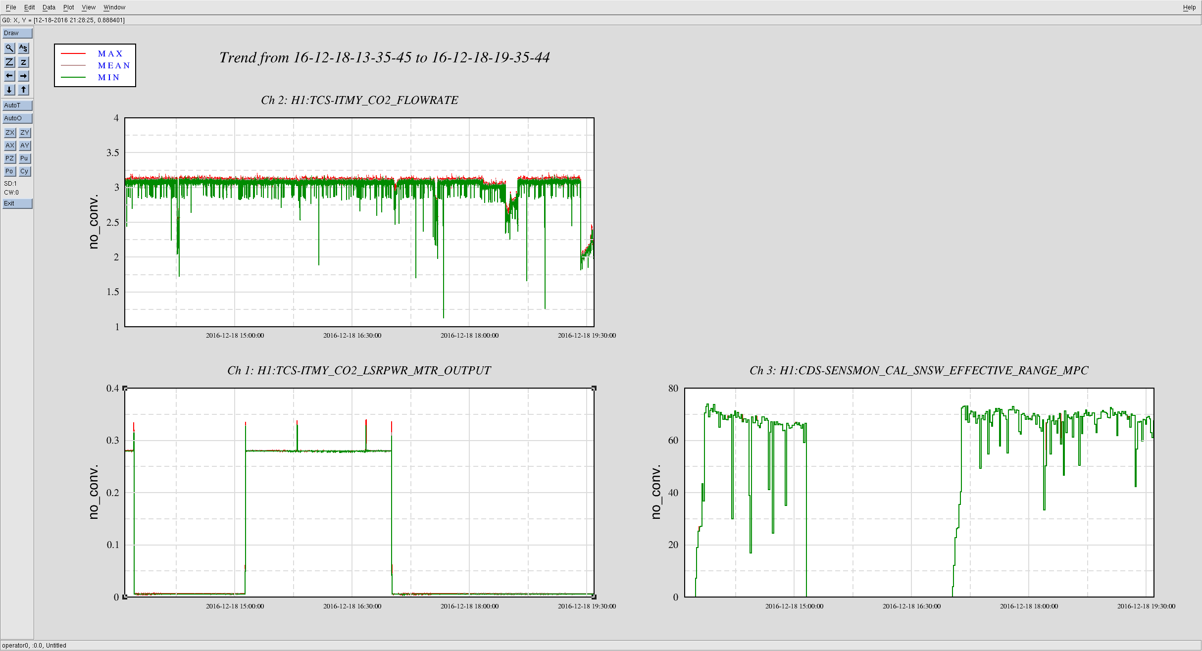
I just spoke to Corey by phone. This is the same problem we have been seeing with the flow sensor. Corey has checked the power output of the laser ( at the thermopile on the laser output, which has a channel name of LSR_HD_PD_OUTPUT) and the laser is running and giving approx 56W. So it has not tripped off.
Altering the power output to the CP using the rotation stage would cause a change in the power registered at the power meter ( PWM_MTR_OUTPUT ) so assuming the IFO is setup to alter power during locking then you would expect that change. Will double check with commisioners what the standard settings are for power output during lock.
I'll check with Betsy/Jason/Nutsinee when they're planning on doing the flow meter swap out. It would be good to do it sooner rather than later I think, otherwise it could start tripping off that laser and putting us out of observing mode.