|
Work Permit |
Date |
Description |
alog/status |
|
6428.html |
2017-01-10 09:19 |
Replace TCSY Laser Controller D1200745. This work is related to the flow sensor alarms/glitches. The in-line flow sensor was replaced on Dec. 20, but glitches were seen after swap. See Alog 32776. Planning on doing work this or next Tues. |
33129 |
|
6427.html |
2017-01-10 07:55 |
Investigate Condenser Fan VFD fault on the end station chiller. |
End Y work deferred. Blocked by snow. |
|
6426.html |
2017-01-10 07:50 |
Shut down AHU-4 to investigate air flow issues. This air handler supplies the OSB office area. Apollo will need to cut into the duct to be able identify the blockage. This has also been reported to HFD because of the smoke sensors in the duct, therefore the fire system for the OSB will be down for this work. |
|
|
6425.html |
2017-01-09 17:57 |
Investigate apparent clipping discovered by J. Kissel recently. We'll need to unlock the MC temporarily to eliminate the 1064 nm light for Pcal camera images. We expect the work to take less than two hours. |
End Y work deferred. Blocked by snow. |
|
6424.html |
2017-01-09 15:01 |
Upgrade BRS analysis software to reduce auto-collimator non-linearity. See last paragraph of SWG aLOG 11414. |
33128 |
|
6423.html |
2017-01-09 15:00 |
Install PEM STS on to Modified BRS Y Mounting Plate to explore for better coherence and/or subtraction of tilt at EY. Installation on Tue during maintenance. STS will remain there for the foreseeable future. No new digital infrastructure should be needed. For details, see SEI aLOG 1090. |
33128 End Y work deferred. Blocked by snow. |
|
6422.html |
2017-01-09 11:51 |
Remove connected auxiliary pumps from PT180 hardware*Requires venting small turbo pump which is currently bolted to but isolated from PT180's pump port, removing connected pump and replacing with the nominal 1.5" redundant O-ring valve*Will then pump O-ring valve to rough vacuum and isolate*Work requires use of ladder leaning against BSC8 |
33137 |
|
6421.html |
2017-01-09 11:27 |
Replace fried ion pump #5 controller (located in mech. room) and update CDS signal cabling. |
33133 & 33105 |
|
6420.html |
2017-01-09 07:51 |
Increases OMC dither line amplitude for 1 hour test. (https://alog.ligo-wa.caltech.edu/aLOG/index.php?callRep=33037) I will do this when LLO is down but may try to do it remotely. |
33104 |
|
6419.html |
2017-01-06 16:11 |
Test adding a boost to OMC length loop, because of evidence that OMC length noise is showing up in DARM from alog 33037 |
33104 |
|
6418.html |
2017-01-05 08:02 |
Move trend writer 1 raw minute files from h1tw1 SSD RAID to h1fw1 SATAboy RAID. Will require a reconfiguration and restart of the nds system on h1nds0 and h1nds1 at the start and end of the process. This is a maintenance task that needs to be performed about every 6 months. Expected duration 3-5 days. |
33127 |
|
6417.html |
2017-01-04 11:20 |
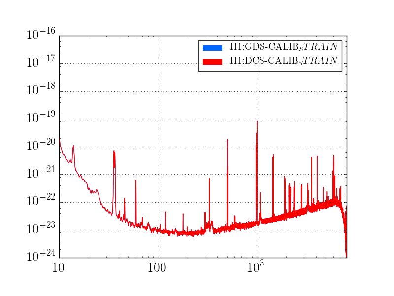
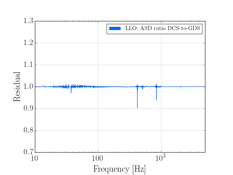
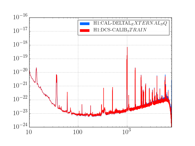
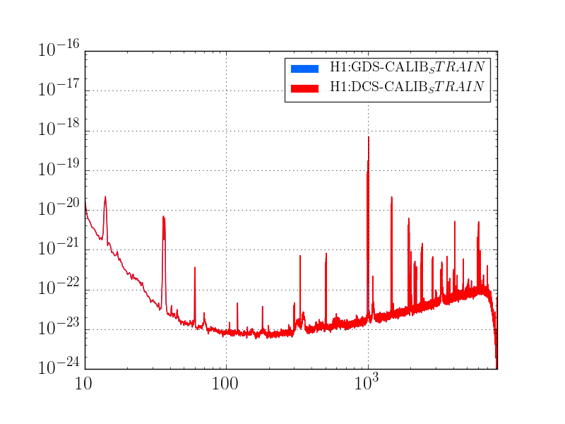
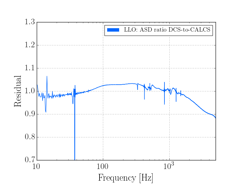
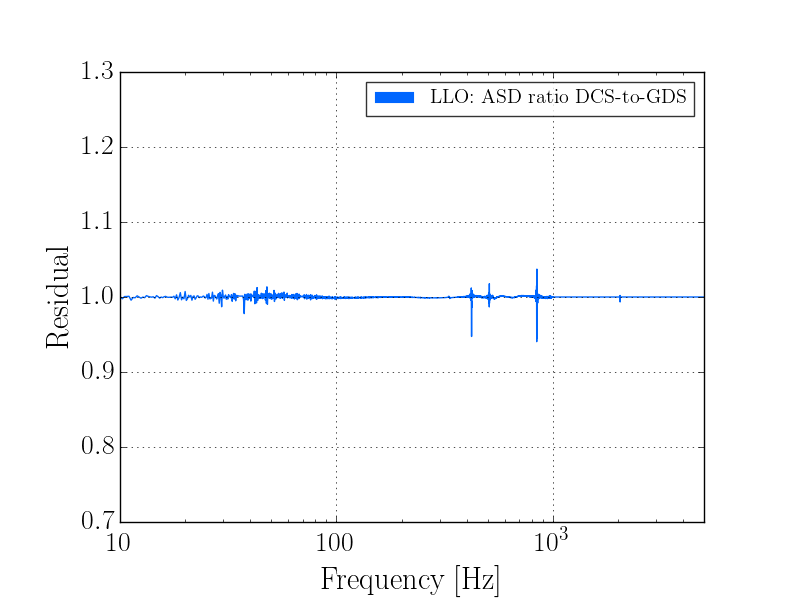
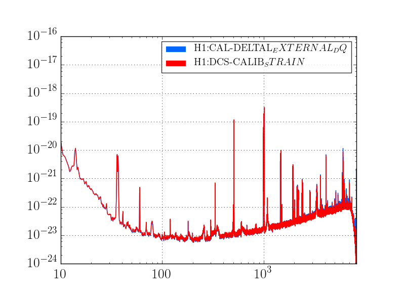
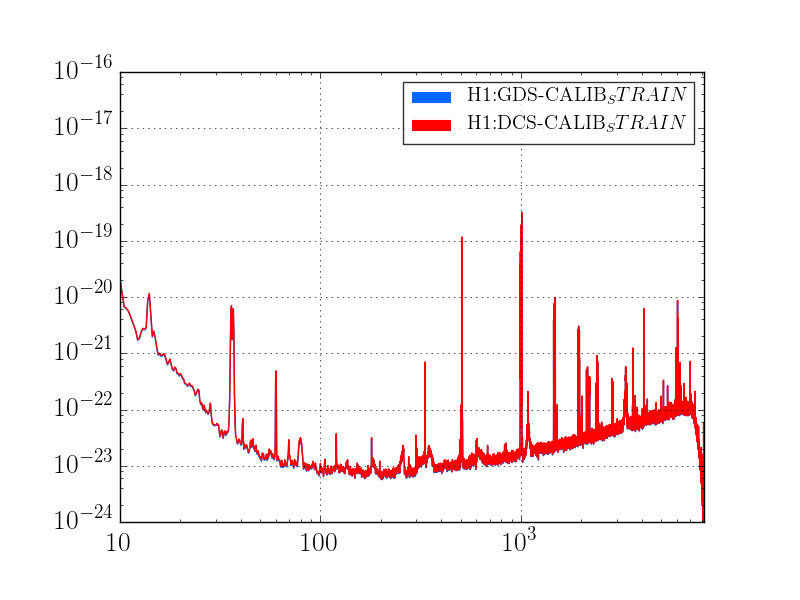
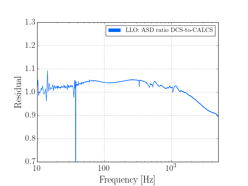
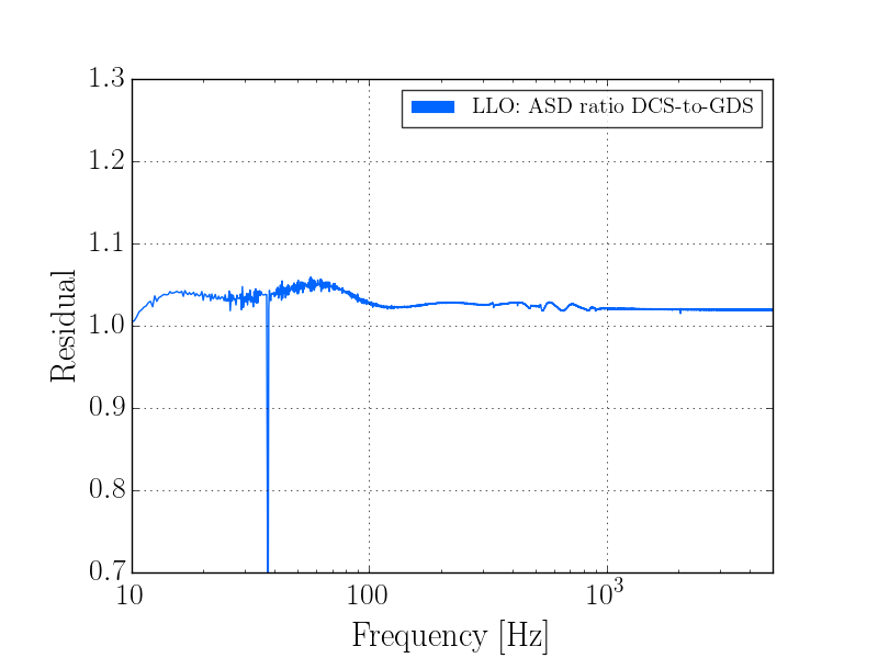
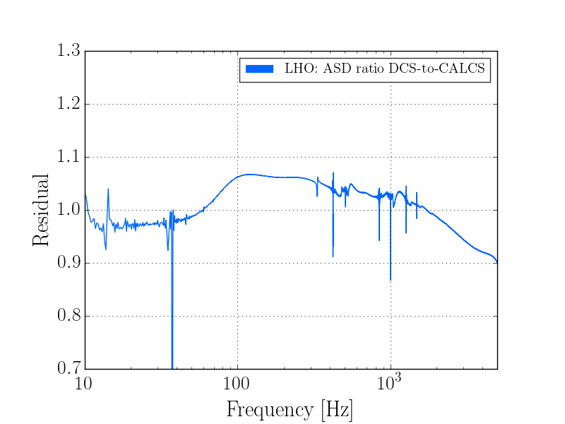
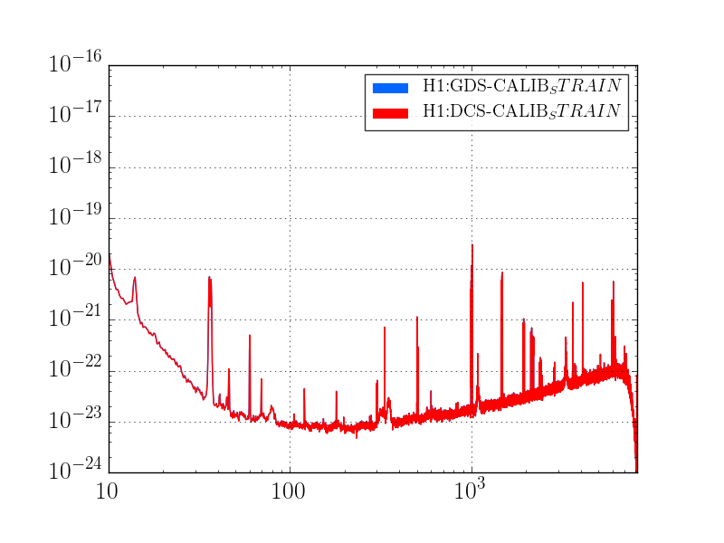
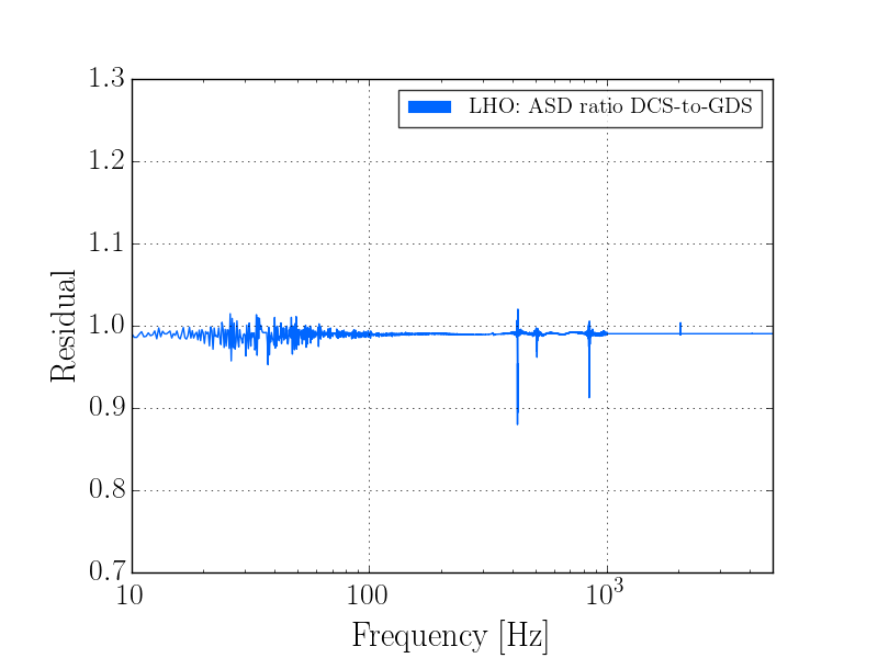
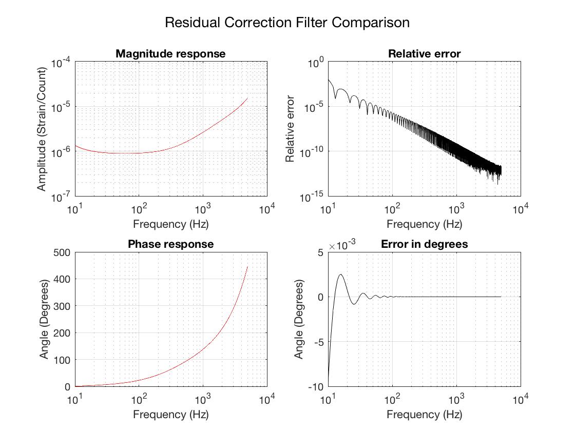
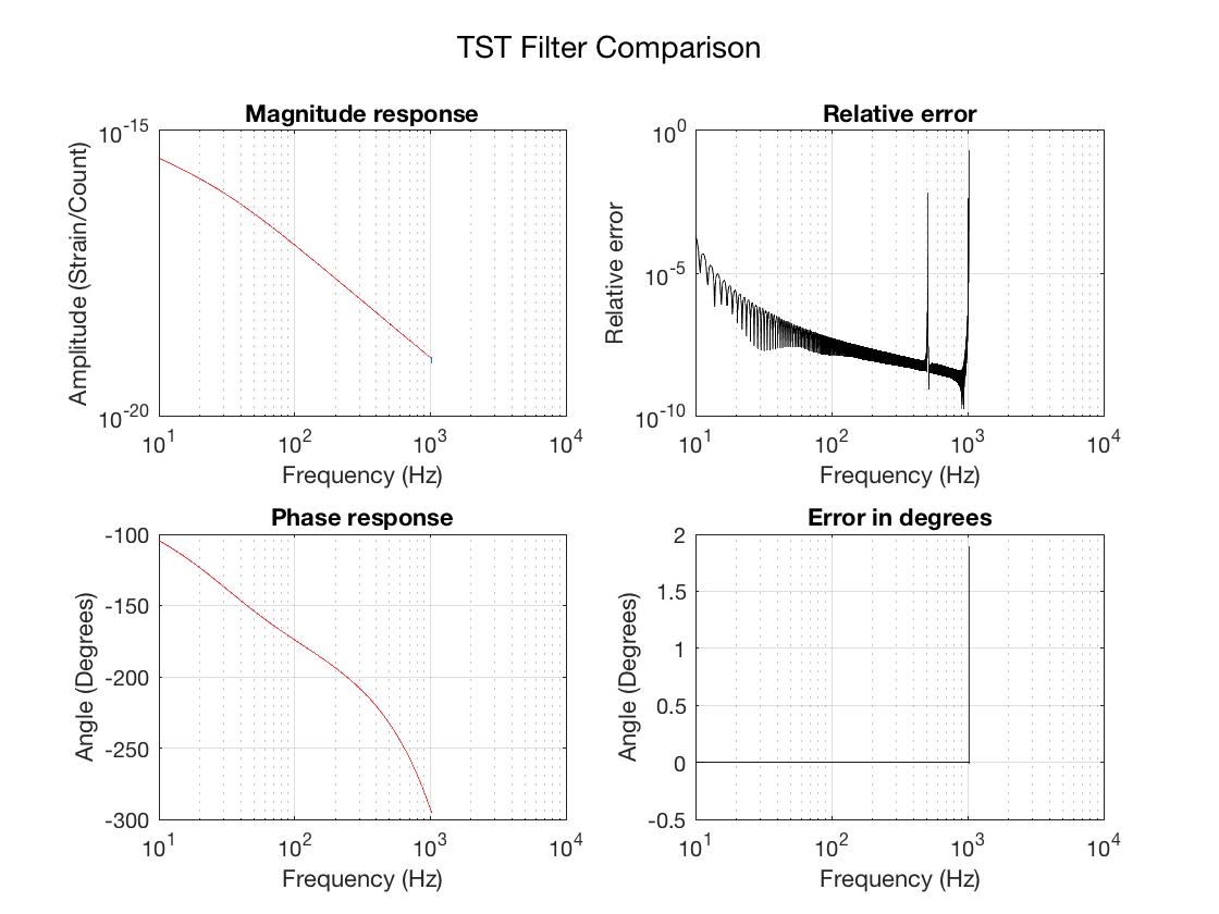
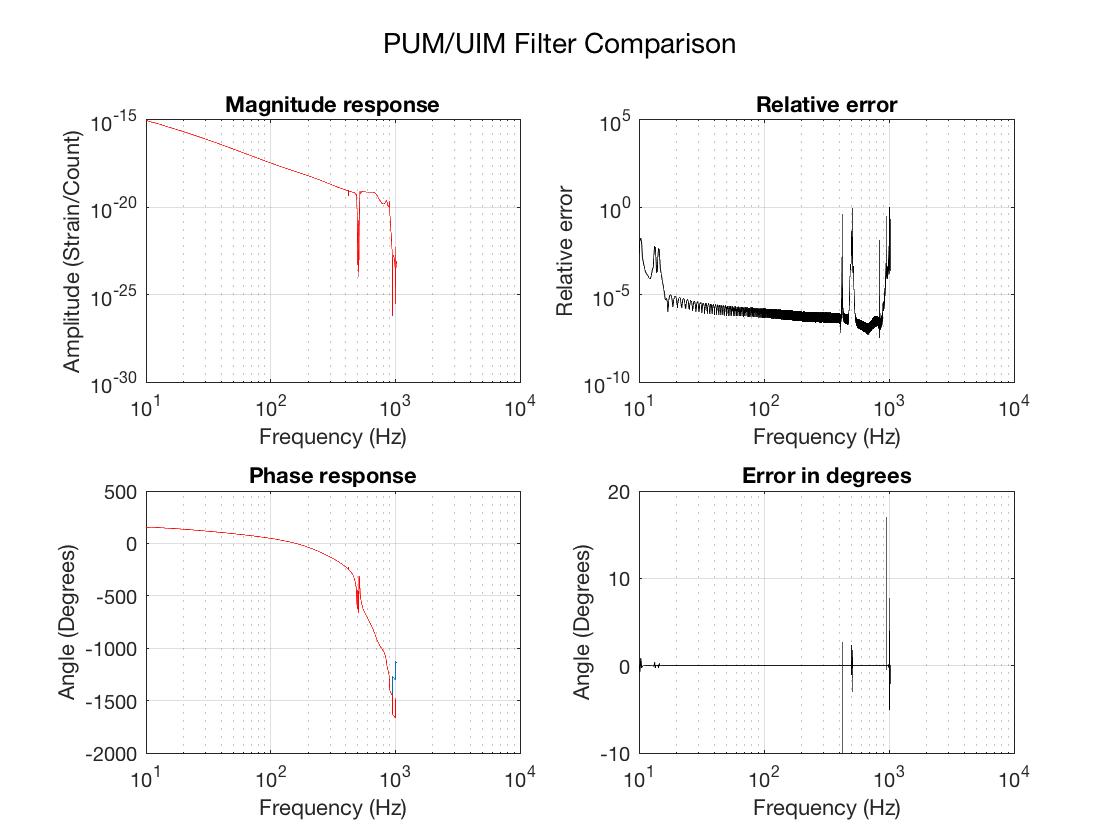
Retroactive work permit; discussed and approved a prior to work done with Keita and JRPC. Update the PUM/TST or L2/L3 actuation heirarchy filters to restore new and improved design from LHO aLOG 28746. See discussion in LHO aLOG 32933. Update front-end calibration to compensate for it. Also update front-end to include bug fix for missing 1% from analog AA and AI filters. See LHO aLOG 32907 for details. Run calibration measurement suite to confirm new results. (Already done, see LHO aLOG 32942). |
|
|
6416.html |
2017-01-03 16:25 |
Similar to LLO upgrade, upgrade LHO CW hardware injection code to version 1.15.0.1. Requires restart of ps-inject on h1hwinj1. |
|
|
6415.html |
2017-01-03 08:03 |
Install HVAC Controls Upgrade. This will involve accessing VAV boxes and pulling new thermostat wire in the OSB. Out building work will be scheduled on a "as we can get access to them" basis. |
|
|
6414.html |
2016-12-29 11:36 |
Tour of LVEA & VEAs (while performing holiday inspection). |
|
|
6413.html |
2016-12-22 07:18 |
This work permit is mostly to inform that I will be on site beginning Tuesday the 27th with various contractors working at the LSB to try and minimize additional disruption that would occur after the holiday break. Some of this work may last through the week of the break. |
|
|
6412.html |
2016-12-21 17:26 |
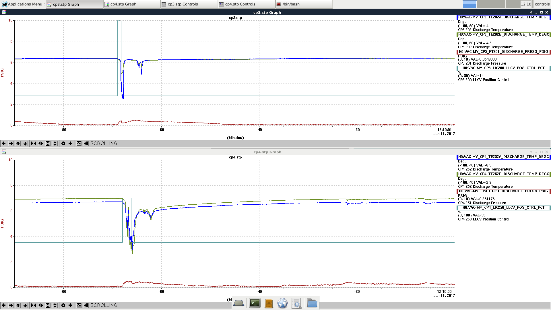
Add all cryo-pump discharge line pressures to the cell phone alarm system. Alarms will be raised if the pressure exceeds 2.0 PSI for an extended time, or the Beckhoff error channels show errors. |
|
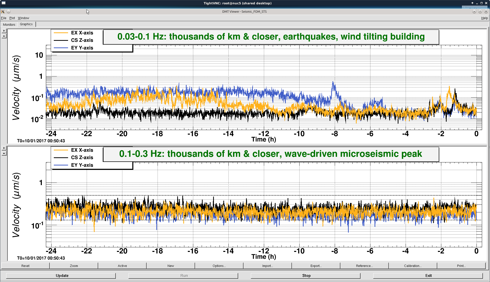


This was a low magnitude but relatively close event which implies higher frequency ground motion. You can see a spike in the 0.3-1 Hz blrms at the lockloss time. I suspect that is what caused the lockloss.