edmond.merilh@LIGO.ORG - posted 18:15, Tuesday 03 January 2017 (32941)
TCSY chiller flow is low alarms
Two alarms so far 5 minutes apart. Trends don't really show anything obvious.
Two alarms so far 5 minutes apart. Trends don't really show anything obvious.
Thu 22nd Dec - Sat 24th Dec No restarts reported
Sun 25 Dec Many unexpeced restarts of h1tw0 (05:35 - 13:10). System turned off to prevent further restarts.
Mon 26th Dec - Fri 30th Dec No restarts reported
Sat 31st Dec
2016_12_31 15:57 h1iopsusauxh34
2016_12_31 15:57 h1susauxh34
h1susauxh34 computer died, was power cycled.
Sun 1st Jan - Mon 2nd Jan No restarts reported
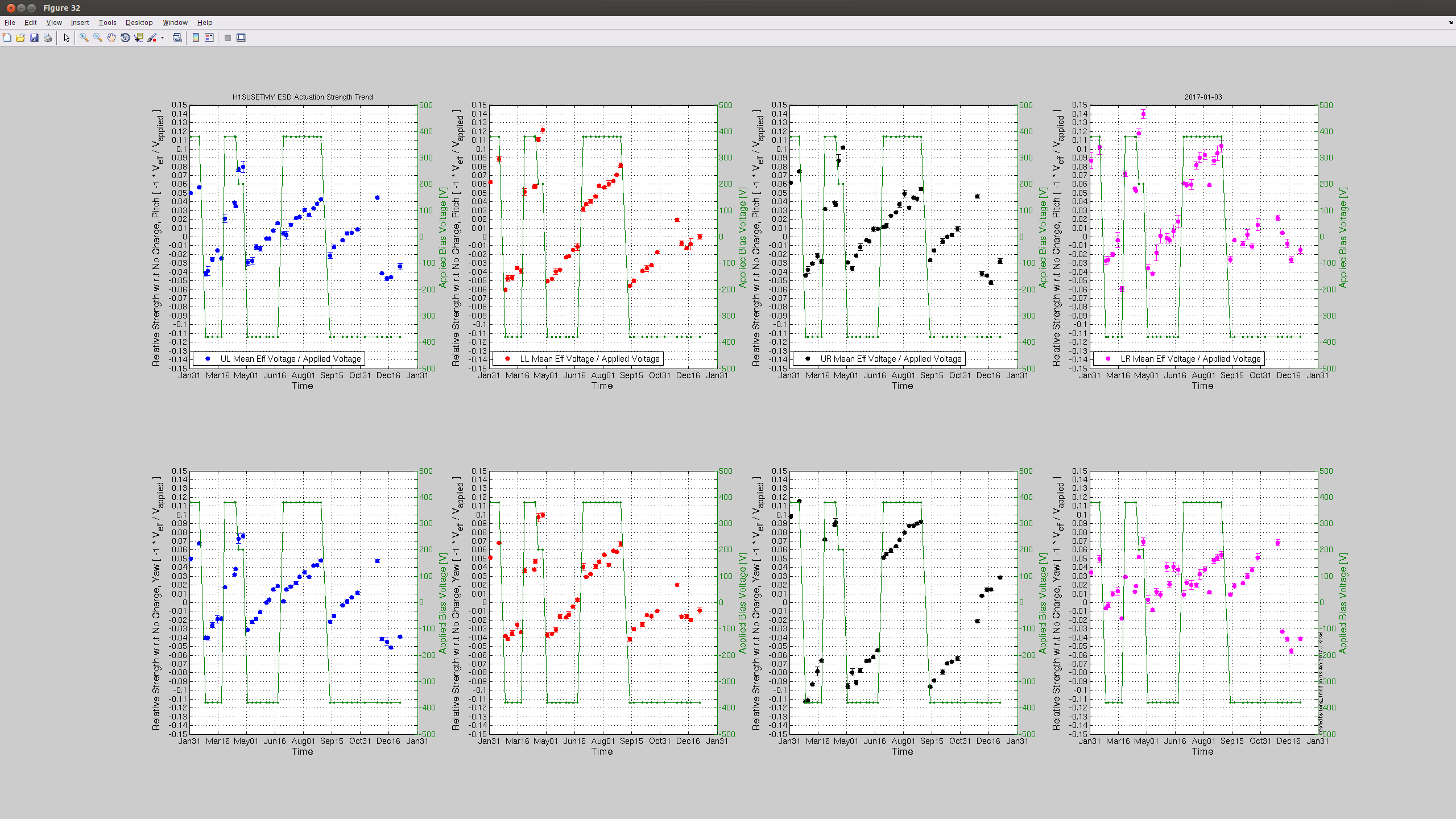
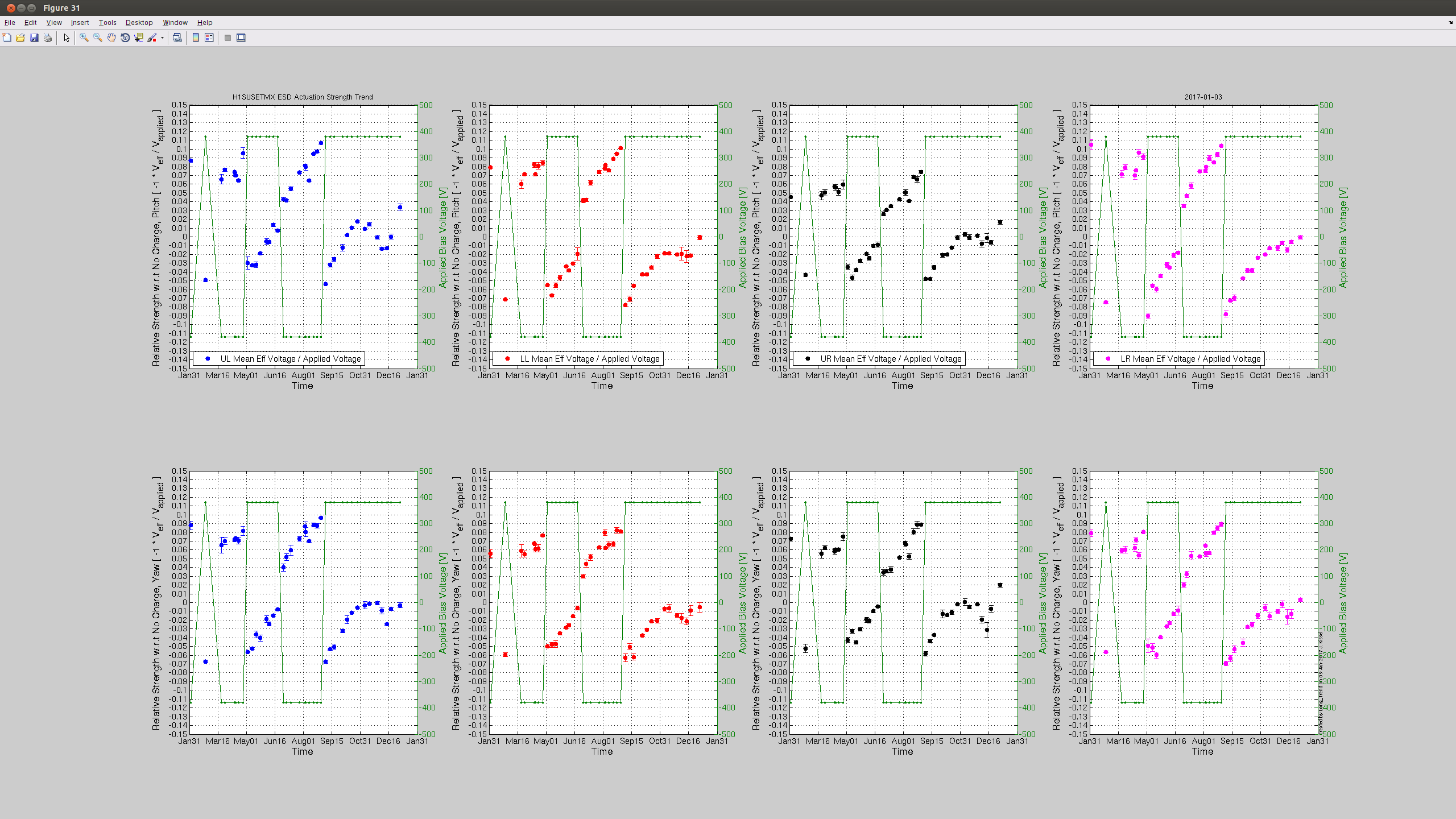
J. Kissel

I've grabbed traditional "charge" (effective bias voltage due to charge) measurements from H1 SUS ETMX and ETMY this afternoon while under an earthquake. Measurments show that the effective bias voltage is still holding around / under +/-10 [V] in all quadrants. Nice!

Still on the to-do list: compare this against longitudinal actuation strength measurements via calibration lines, a. la. LHO aLOG 24547. Perhaps our new years resolution can be to start this regular comparison up again.


awgtpman issues
Jenne, Dave, Jim:
we experienced some TP issues this morning. Command line "diag -l" was slow to start and did not support testpoints. First we restarted the models on h1susauxh34 since this showed errors over the break and had CRC errors, this did not fix the TPs. Next we restarted the awgtpman process on h1asc and this did fix the problems. Remember that h1asc has a special awgtpman process to permit more testponts to be opened. The reason for today's problem is unknown.
Guardian reboot
Dave, Jim:
To ensure the python leap-second updates were installed on all nodes, we rebooted h1guardian0 (it had been running for 33 days). All nodes came back with no problems. We recovered about 4GB of memory.
python gpstime leapseconds
Jim
gpstime package updated, see alog 32919 for details.
Jeff K, Jonathan, Jim, Dave:
For due diligence we performed some sanity tests on the DAQ to confirm the leap-seconds did not cause any problems.
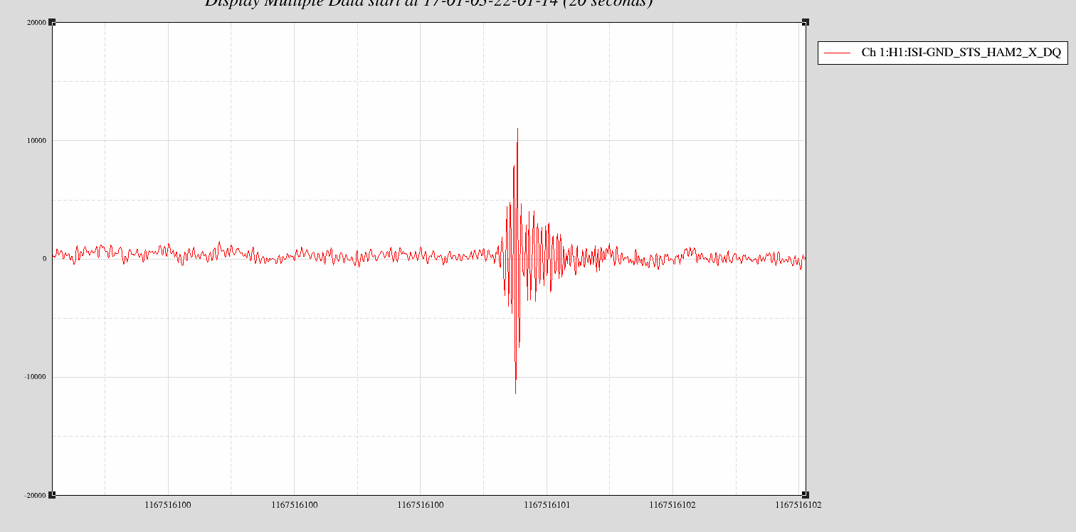
Event at Known Time:
Jeff K dropped a ball onto the control room floor at a recorded time. We looked at a seismometer signal (e.g. H1:ISI-GND_STS_HAM2_X_DQ) using both NDS1 (dataviewer and command-line) and NDS2. The signal showed up in the latter part of the recorded second as expected.
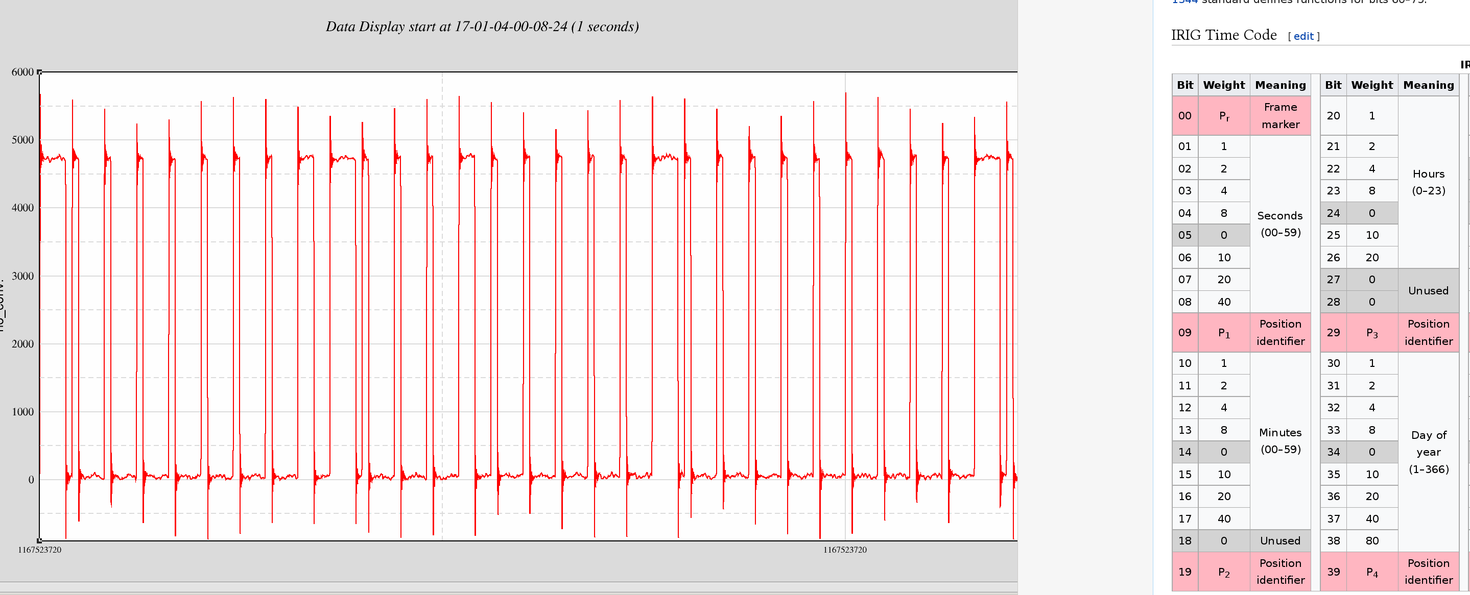
Decode IRIG-B analog signal:
The digitized IRIG-B signal H1:CAL-PCALX_IRIGB_OUT_DQ was read by hand for an arbitary GPS time. The time chosen is GPS = 1167523720 which corresponds to a UTC time of Jan 04 2017 00:08:22.
The decoded IRIGB time is 00:08:40 which is UTC + 18. Tthere have indeed been 18 leap seconds applied to UTC since the GPS epoch of Jan 1980, this is correct.
For anyone interested in decoding irig-b by hand, the attached image shows the seconds, minutes, hours part of the analog signal along with the decoding table.
TITLE: 01/03 Day Shift: 16:00-00:00 UTC (08:00-16:00 PST), all times posted in UTC
Restoring From Holiday Log Notes:
John, Kyle, Alfredo, Gerardo

X2-8 battery charge a little low but still had lots of life left.
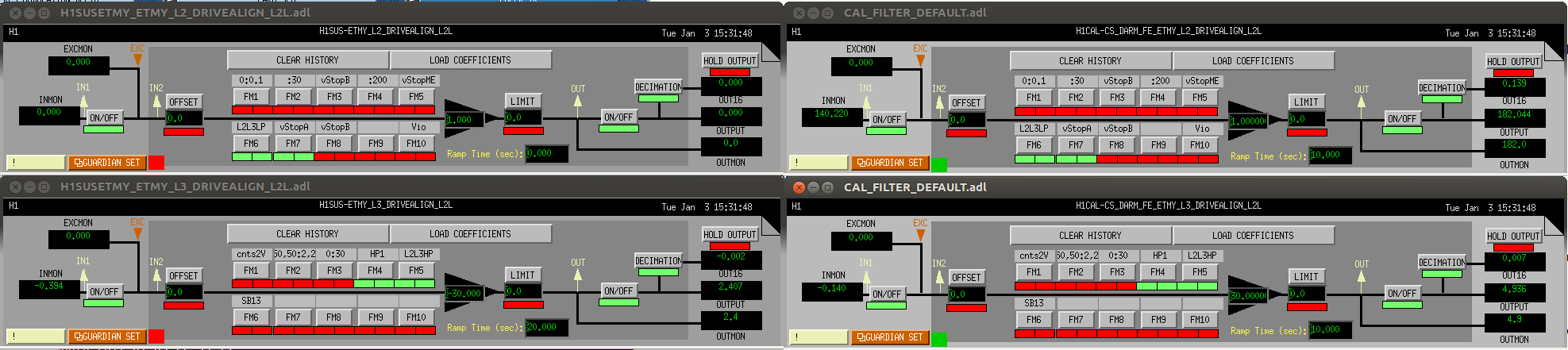
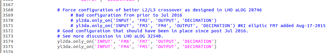
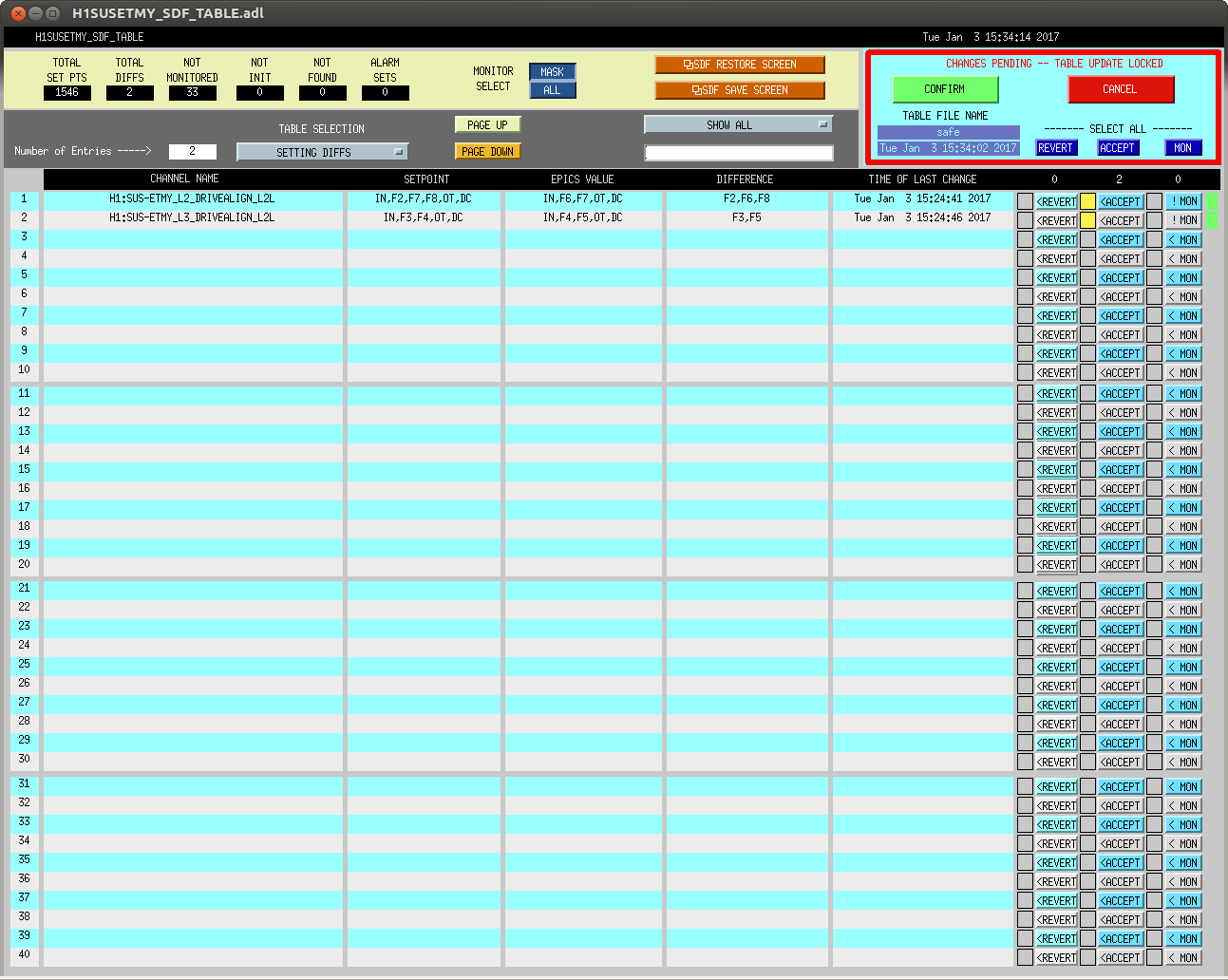
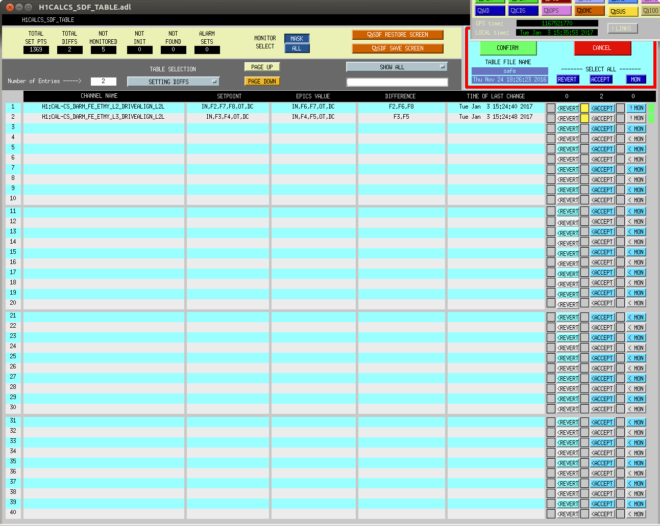
J. Kissel

Before the holiday break, I'd discovered that we had somehow lost the settings improved the design of the L2/L3 (or PUM/TST) crossover -- see LHO aLOG 32540 for the bad news discovery, and LHO aLOG 28746 for the original design.

I've now fixed the problem, and we have the new improved crossover again.

This required several steps:
(1) Turned on / switched over to the appropriate filters in the L2 and L3 DRIVEALIGN_L2L filter banks:
                  Good               Bad
     L2 L2L    (FM6, FM7)       (FM2, FM7 ,FM8)
     L3 L2L    (FM4, FM5)       (FM3, FM4)

(2) Turned on / swtiched over to the appropriate filters in the corresponding replicas of those filter banks in the CAL-CS model, such that the calibration will be unaffected.

(3) Changed the LOWNOISE_ESD_ETMY state of the ISC_LOCK guardian, such that it now forces the new configuration instead of the old. Committed to the userapps repository.

(4) Accepted the changes in the H1SUSETMY and H1CALCS SDF systems.

Hopefully we won't lose these settings again!
While waiting for the ground to stop shaking, I ran throught Betsy's annotated LVEA sweep. I didn't find anything out of place, I did run through the science mode process for the PSL (unclear if that was necessary, I got the impression from the checksheet on the PSL that it was). Everything else seemed okay. I don't believe the ends have been done, but access is dicey today.
We just lost the first NLN lock of the year to a 7.2 earthquake in Fiji. Terramon predicts 18 micron displacements, so we wanted to turn off the low frequency feedforward on the ISIs. Unfortunately, CDS had restarted all of the guardians right after the lockloss, so we couldn't use ISI_CONFIG to do this. TJ had written a script to do this a while ago (before & independent of the seismic configuration guardians) and I had an alias set up to run it. This script conflicts with the seismic guardians however, so just re-requesting "WINDY" on ISI_CONFIG may not recover the correct configuration. So, to ensure that we get everybody back to where they belong, we should run the following command in a terminal:
python /opt/rtcds/userapps/release/isi/h1/scripts/Toggle_SEI_Sensor_Correction.py -c 1 && python /opt/rtcds/userapps/release/isi/h1/scripts/Toggle_SEI_Sensor_Correction.py -e 1
Should just be copy/paste, any issues will show up in SDF, so that would be a good check. The only ISI that should be red in the down state is the BS, with 21 diffs. All ISI and HEPI should be green in OBSERVE.
This is not a long term issue, just a kludge I had to use because of poor timing with CDS work.
Corey has reverted this. Unless CDS takes guardian down again at another perfectly disoptimal time, no further action is needed.
After alignment and moderate troubleshooting, we had H1 aimed toward NOMINAL LOW NOISE at 2pm PST, but as we were approaching, a big EQ (7.2, Fiji) was incoming. Managed one data point of around 65Mpc before dropping out. Jenne was in the middle of ACCEPTING many OFFSET changes from her Dark Offset Measurements (not sure she accepted all of them).
Taking this opportunity of down-time to address a few items:
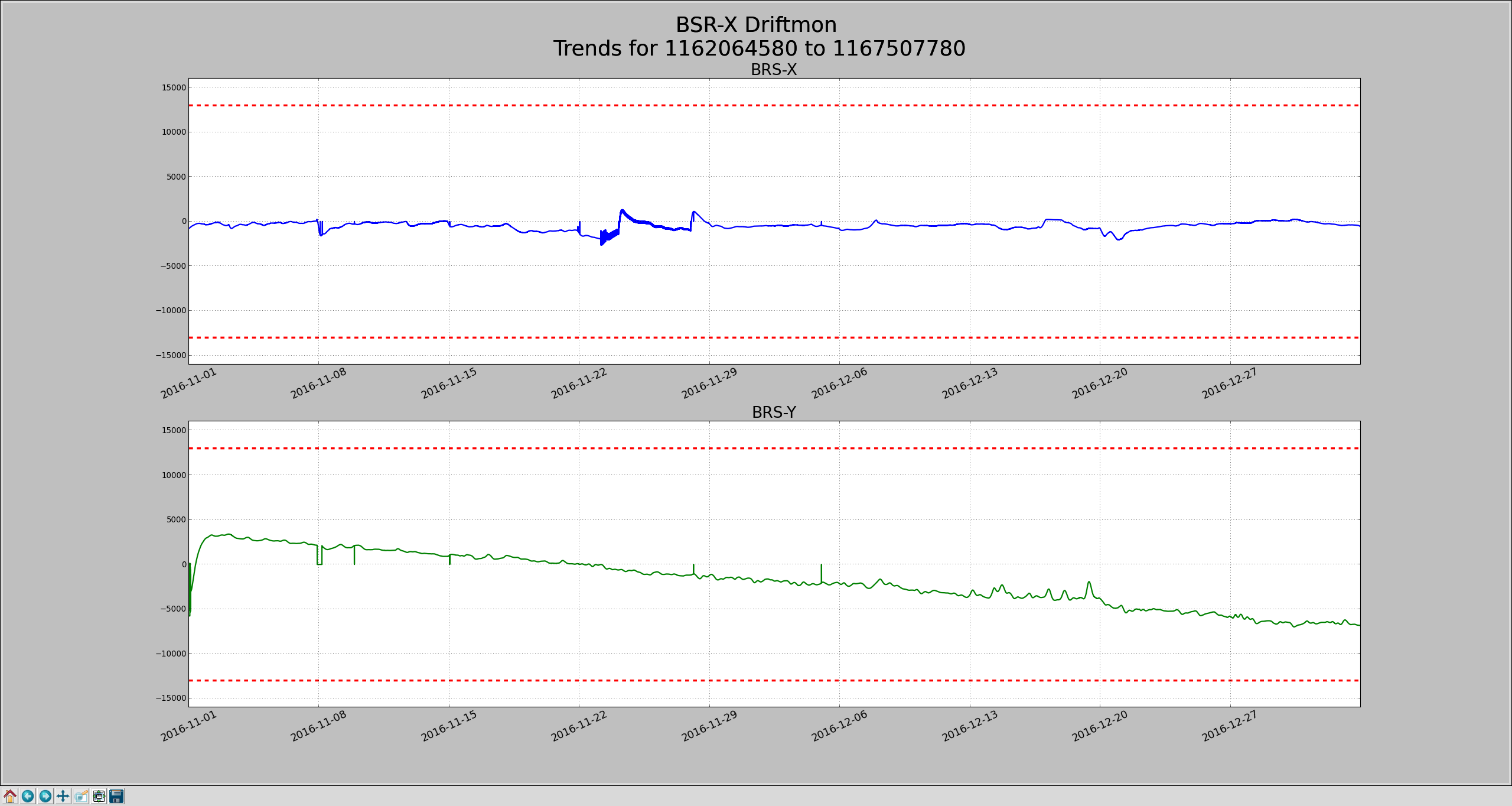
One of the things I checked this morning the health of the 3 different BRSs on site. Everybody looks ok: the corner station BRS guardian was still running smoothly, EX doesn't look like it did anything crazy and EY continues a slow (and slowing) drift toward one limit. Attached time series are the Drift mons for both end BRSs, blue is EX, green is EY. EY has drifted about 10k counts in 9 weeks, it's got about 8k counts margin left, about 7.5 weeks.
I reset the dark offsets for all LSC and ASC PDs. The ASC diodes already had scripts in ..../userapps/asc/common/scripts/dark_offset/, so I copied the style of those into an LSC script that now lives in ..../userapps/isc/common/scripts/dark_offset/.
I also created a bash script that will call each of those scripts in succession - it's natively in the isc folder, but linked in the asc folder: all_offsets_LSCandASC.
For last lock, and the one that Ed just got, we've had SDF diffs due to not rounding in one of the pre-existing dark offset scripts (the one that does the end station QPDs). The diffs were of the order 1e-16, so were just accepted so that we can Observe. I have modified (although not run, since we just locked) the script such that we have rounding. This should prevent the problem in the future. Next time we lose lock and I'm around, I'll try to remember to hand-round those values so that we don't keep getting non-useful SDF diffs.
Also, Ed might write about this in his shift summary, but it seems like the ASAIR_LF offset was set a little wrong. Sheila and Ed took the IMC to offline and hand-set that offset, and we were able to get through the PRX_Locked state of initial alignment. (The wrong dark offset was causing the output to not meet the guardian's threshold of whether the cavity was locked or not, even though it was locked).
Looks like a number of seismometers are out of shape, especially the corner station ground STS, 6 volts seems pretty bad relative to the 2 volt spec.
Averaging Mass Centering channels for 10 [sec] ...
2017-01-03 12:04:38.352808
There are 2 STS proof masses out of range ( > 2.0 [V] )!
STS B DOF Y/V = -6.441 [V]
STS B DOF Z/W = 4.384 [V]
All other proof masses are within range ( < 2.0 [V] ):
STS A DOF X/U = -0.486 [V]
STS A DOF Y/V = 0.035 [V]
STS A DOF Z/W = -0.568 [V]
STS B DOF X/U = 0.986 [V]
STS C DOF X/U = -0.0 [V]
STS C DOF Y/V = -0.0 [V]
STS C DOF Z/W = -0.0 [V]
STS EX DOF X/U = -0.089 [V]
STS EX DOF Y/V = 0.557 [V]
STS EX DOF Z/W = 0.126 [V]
STS EY DOF X/U = 0.168 [V]
STS EY DOF Y/V = 0.084 [V]
STS EY DOF Z/W = 0.464 [V]
Assessment complete.
jim.warner@opsws0:~ 0$ t240_center
Averaging Mass Centering channels for 10 [sec] ...
2017-01-03 12:16:41.356637
There are 12 T240 proof masses out of range ( > 0.3 [V] )!
ETMY T240 3 DOF Z/W = 0.405 [V]
ITMX T240 1 DOF X/U = -0.589 [V]
ITMX T240 1 DOF Y/V = 0.355 [V]
ITMX T240 1 DOF Z/W = 0.31 [V]
ITMX T240 2 DOF X/U = 0.346 [V]
ITMX T240 2 DOF Y/V = 0.35 [V]
ITMX T240 2 DOF Z/W = 0.358 [V]
ITMX T240 3 DOF X/U = -0.573 [V]
ITMY T240 2 DOF Z/W = 0.306 [V]
ITMY T240 3 DOF Z/W = -1.025 [V]
BS T240 1 DOF Z/W = 0.423 [V]
BS T240 2 DOF Y/V = 0.393 [V]
All other proof masses are within range ( < 0.3 [V] ):
ETMX T240 1 DOF X/U = 0.136 [V]
ETMX T240 1 DOF Y/V = 0.099 [V]
ETMX T240 1 DOF Z/W = 0.157 [V]
ETMX T240 2 DOF X/U = -0.137 [V]
ETMX T240 2 DOF Y/V = -0.252 [V]
ETMX T240 2 DOF Z/W = 0.039 [V]
ETMX T240 3 DOF X/U = 0.091 [V]
ETMX T240 3 DOF Y/V = 0.075 [V]
ETMX T240 3 DOF Z/W = 0.085 [V]
ETMY T240 1 DOF X/U = 0.046 [V]
ETMY T240 1 DOF Y/V = -0.065 [V]
ETMY T240 1 DOF Z/W = -0.099 [V]
ETMY T240 2 DOF X/U = 0.256 [V]
ETMY T240 2 DOF Y/V = -0.135 [V]
ETMY T240 2 DOF Z/W = 0.038 [V]
ETMY T240 3 DOF X/U = -0.108 [V]
ETMY T240 3 DOF Y/V = 0.049 [V]
ITMX T240 3 DOF Y/V = 0.281 [V]
ITMX T240 3 DOF Z/W = 0.262 [V]
ITMY T240 1 DOF X/U = 0.228 [V]
ITMY T240 1 DOF Y/V = 0.153 [V]
ITMY T240 1 DOF Z/W = 0.19 [V]
ITMY T240 2 DOF X/U = 0.092 [V]
ITMY T240 2 DOF Y/V = 0.272 [V]
ITMY T240 3 DOF X/U = -0.111 [V]
ITMY T240 3 DOF Y/V = 0.265 [V]
BS T240 1 DOF X/U = 0.031 [V]
BS T240 1 DOF Y/V = 0.13 [V]
BS T240 2 DOF X/U = 0.231 [V]
BS T240 2 DOF Z/W = 0.218 [V]
BS T240 3 DOF X/U = 0.253 [V]
BS T240 3 DOF Y/V = 0.073 [V]
BS T240 3 DOF Z/W = 0.092 [V]
Assessment complete.
J. Oberling, P. King (from Pasadena)
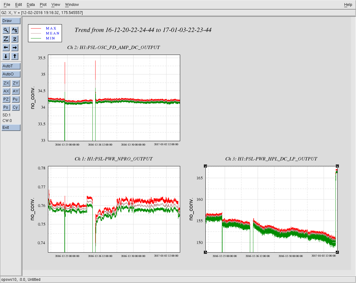
Checked on the PSL this morning, all was fine except we lost ~10 W of power over the break (before the break we were at ~160 W, this morning we were at ~150 W) and the NPRO noise eater needed to be reset. Everything looked as expected, so the power loss is most likely due to natural decay of the HPO pump diodes. I increased the HPO diode currents to recover our lost power; the currents were changed from 50.5 A to 51.0 A for each HPO diode box. I then tweaked the pump diode temperatures, see the table below for a summary of the changes (remember that each HPO diode box has 7 individual laser diodes). The PSL is now outputting ~166.5 W from the HPO box itself (the internal power reading is ~212 W).
|
|
Diode Box 1 | Diode Box 2 | Diode Box 3 | Diode Box 4 | ||||
| Old | New | Old | New | Old | New | Old | New | |
| D1 | 26.0 | 25.5 | 20.5 | 20.0 | 22.5 | 22.0 | 25.0 | 24.5 |
| D2 | 26.5 | 26.0 | 20.0 | 19.5 | 26.5 | 26.0 | 22.5 | 22.0 |
| D3 | 28.5 | 28.0 | 21.0 | 20.5 | 26.5 | 26.0 | 24.0 | 23.5 |
| D4 | 25.0 | 24.5 | 19.0 | 18.5 | 23.5 | 23.0 | 22.5 | 22.0 |
| D5 | 27.0 | 26.5 | 19.0 | 18.5 | 27.5 | 27.0 | 24.5 | 24.0 |
| D6 | 26.5 | 26.0 | 19.5 | 19.0 | 22.0 | 21.5 | 24.5 | 24.0 |
| D7 | 24.0 | 23.5 | 20.0 | 19.5 | 23.0 | 22.5 | 24.5 | 24.0 |
With the ISS off this gives 80 W incident on the PMC, which is the desired incident power for the PMC; the PMC was outputting ~65 W. I then did a quick tweak of the beam alignment into the PMC, only tweaking the horizontal alignment (vertical looked fine), which improved the PMC transmitted power to ~67 W (ISS still off). With the ISS turned back on the PMC is outputting 64.7 W, which is where it was set at the start of O2. Also with the ISS on, the FSS RefCav TPD is reading ~3.6 V, so no adjustment is necessary there. The H1 PSL is ready for the resumption of O2.
Attached is a 14 day trend of the NPRO, FE, and HPO laser powers. As can be seen, the only power drop is seen in the HPO, lending evidence to the power loss being due to natural decay of the pump diodes.
This morning, Jason, Mark and I swapped the assumed-to-be failing TCSY flow sensor which has been showing epochs of glitching and low readout (while other indicators show normal flow, alogs 32712 and 32230). The process to do this was such:
1) Key laser off at control box in rack, LVEA
2) Turn RF off at mezzanine rack, Mech room
3) Turn chiller off on mezzanine, Mech room
4) Turn power off on back of controller box in rack, LVEA (we also pulled the power cable to the sensor off the front of the controller, but it was probably overkill)
5) Close in-line valves under BSC chamber near yellow sensor to-be-swapped, LVEA
6) Quick-disconnect water tubes at manifold near table, LVEA
7) Pulled yelow top off of yellow sensor housing under BSC at the piping, LVEA
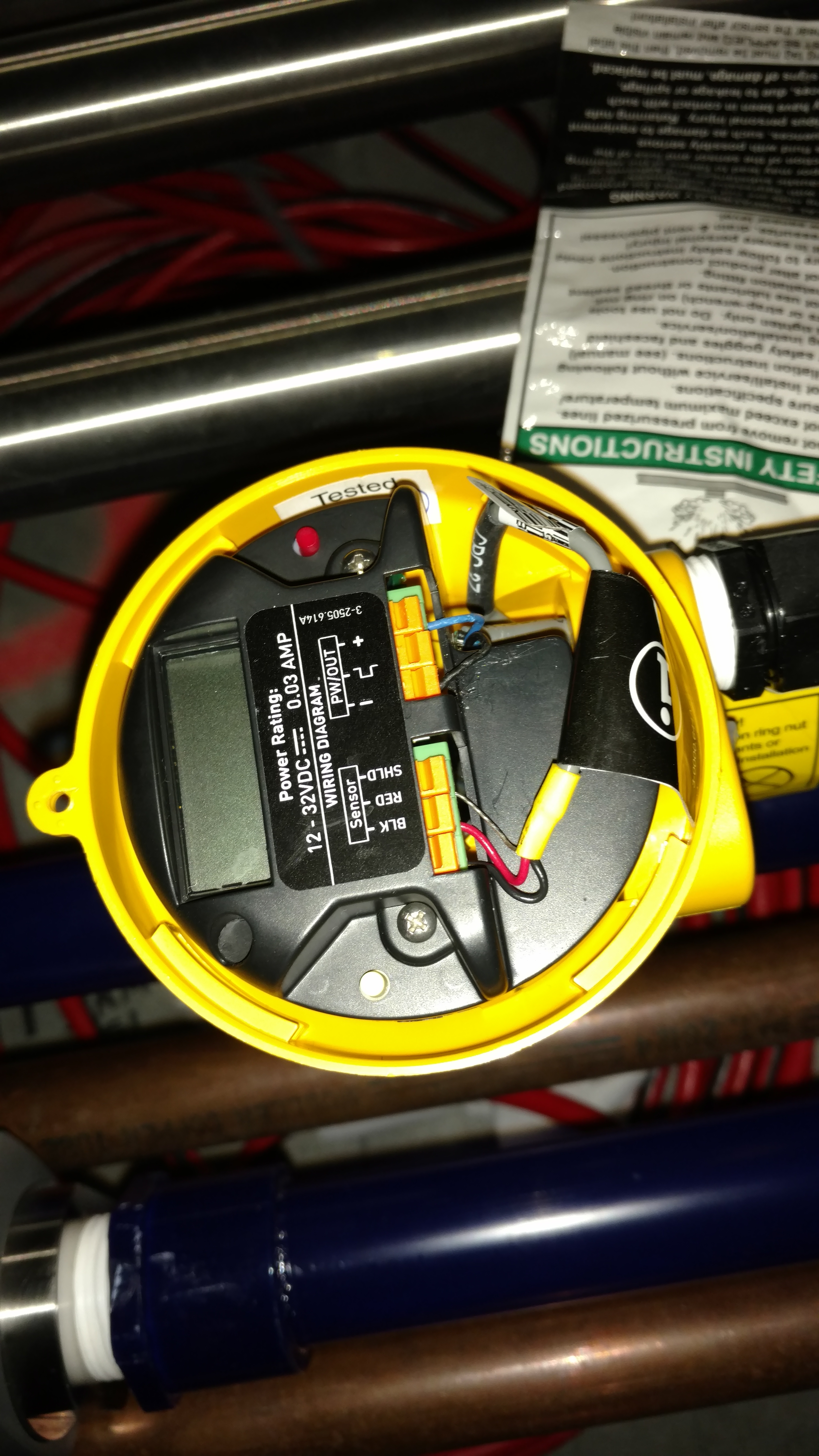
8) Pulled the blue and black wires to the Power recepticles inside the housing (see pic attached). Pulled full grey cable out of housing.
9) While carefully supporting blue piping*, unscrewed large white nut holding housing/sensor to piping (was tough, in fact so tough that we later removed all of the teflon tape which was unneeded in his join)
10) Pull* straight up on the housing (hard) and it comes out of the piping.
11) Reverse all above steps to insert new housing/sensor, wires and turn everything back on. Watch for rolled o-rings on the housing and proper alignment of the noth feature when installing the new sensor. Verify mechanical flow sensors in piping line show ~3-4 G/m readout when flow/chiller is restored to functionality.
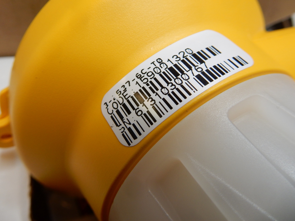
12) Setup new flow sensor head with Settings: Go to the other in-use sensor, pull off the top and scroll through the menu items (red and white buttons on the unit (shown in pic). Set the new head to these values.
13) Verify the new settings on the head are showing a ~3 G/m readout on the medm screen. If not, possibly there is setting on the sensor that needs revisited.
14) Monitor TCS to see that laser comes back up and stabilizes.
* Blue piping can crack so be careful to always support it and avoid torque torque
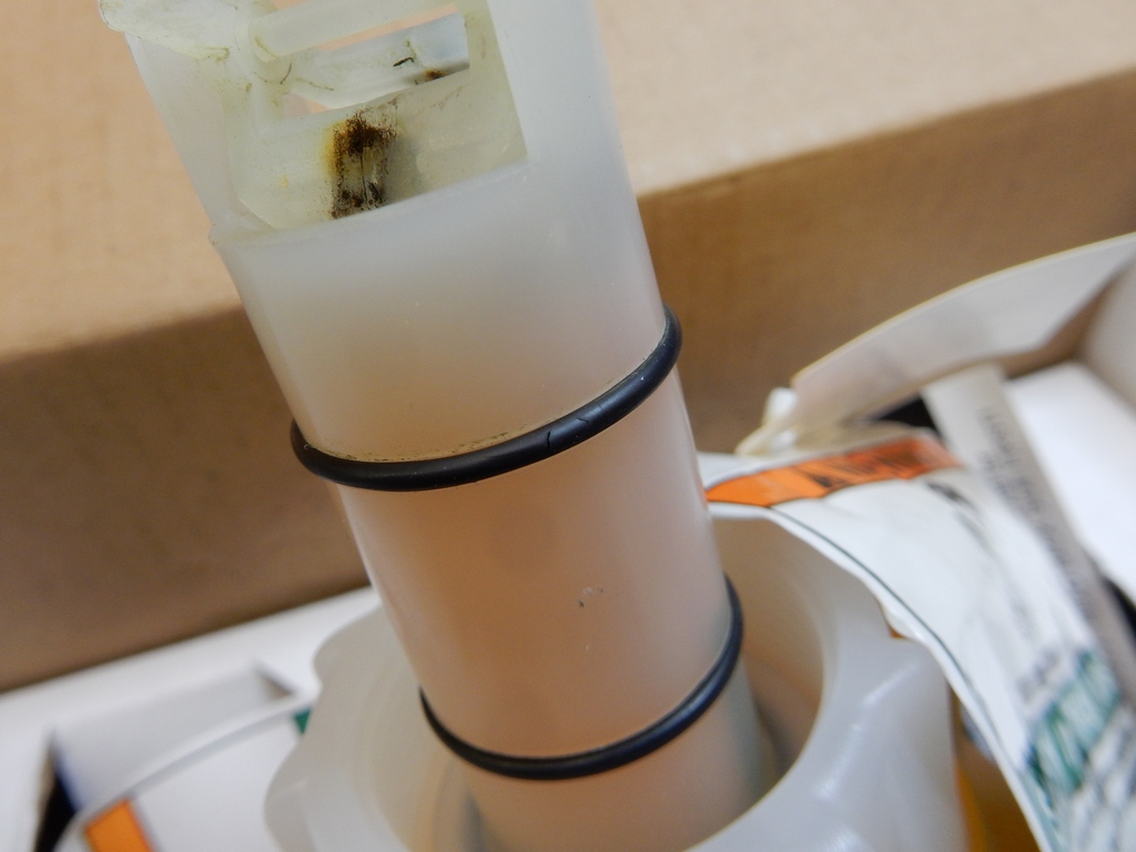
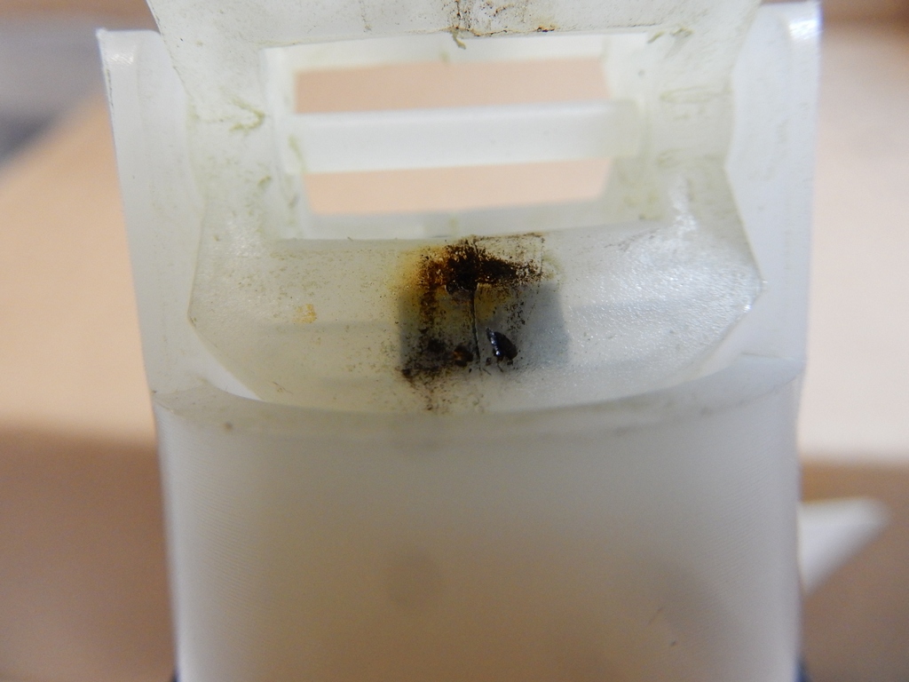
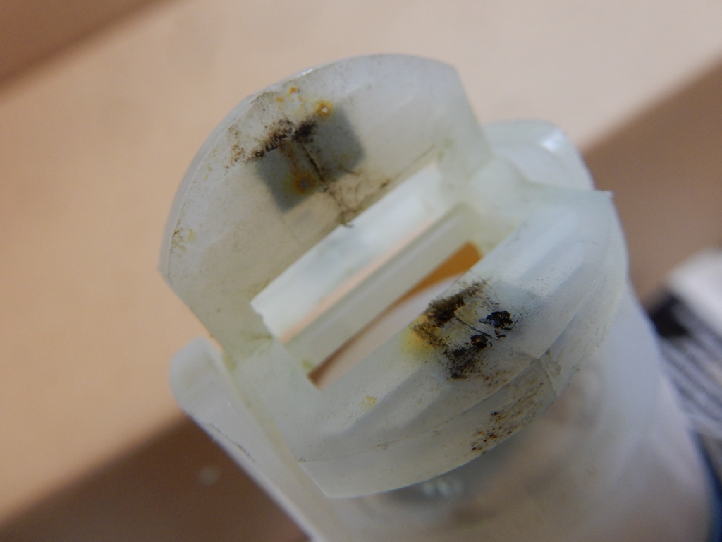
Note - with the sensor removed, we could see alot of green merk in the blue piping where the paddle wheel sits. Still suffering green sludge in this system...
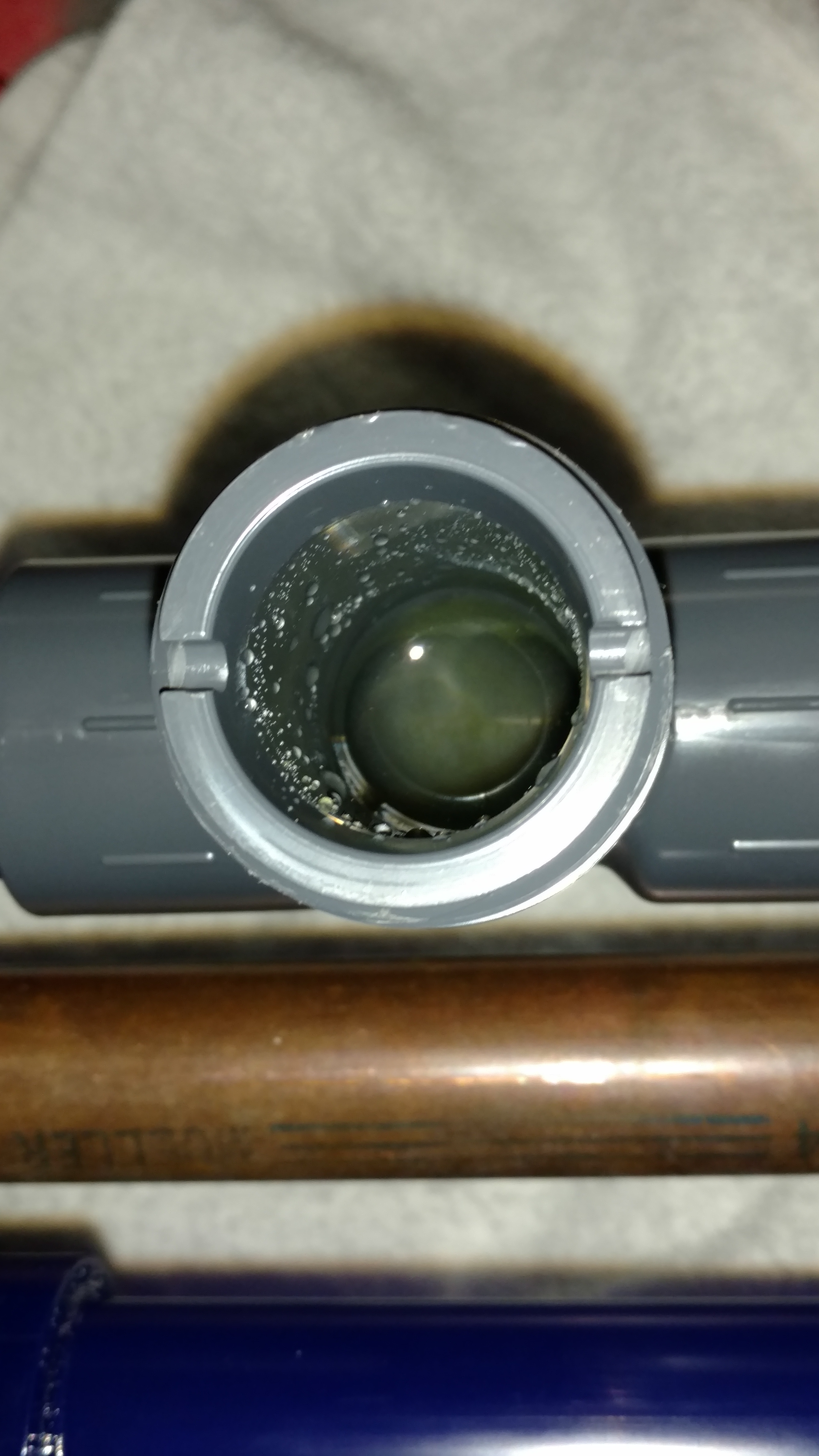
A few pictures to add to those already posted.

The O-ring closest to the paddle wheel had a cut to it.  Not near the electronics,
plus there's the other O-ring so it doesn't look like water was getting into where
the electronics is housed.

Some kind of stuff stuck to each blade (paddle?) of the paddle wheel.  Not a good
sign if the cooling water for the laser is meant to be clean.
Settings were as follows:
FLO Unit (Flow Unit) = G/m (default was L/m)
FActor (K-Factor) = 135.00 (default was 20)
AVErage (Average) = 0
SEnSit (Sensitivity) = 0
4 Set (4mA Set Point) = 0 G/m
20 Set (20mA Set Point = 10 G/m (default was 160)
ContrAST (Contrast) = 3
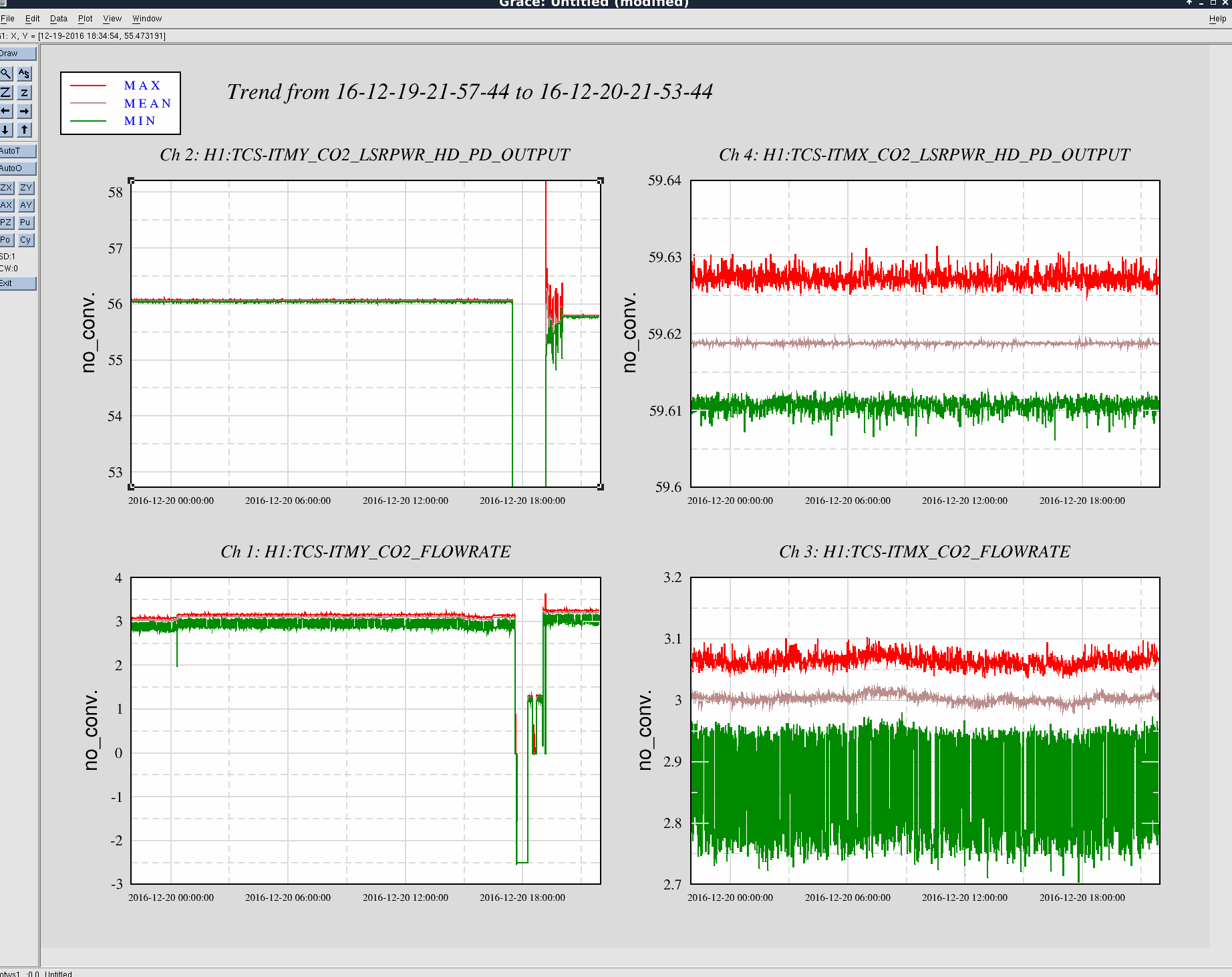
Here's both TCS system laser power and flow for the past day. The drop out in the ITMY data is our few hour sensor replacement work. So far no glitching or low droops. Although, there weren't any for the last 24 hours on the old sensor either.
Attached is a 14 day duration minute trend of the TCSy chiller flow rate and CO2 laser power since our swap of tthe TCSy flow sensor. There have been 7 glitches below 2 GPM, with 3 of those glitches being below 1 GPM; all 7 glitches occured in the last week. Unless the spare flow sensor is also faulty (not beyond belief, but still a hard one to swallow) the root cause of our TCSy flow glitches lies elsewhere.
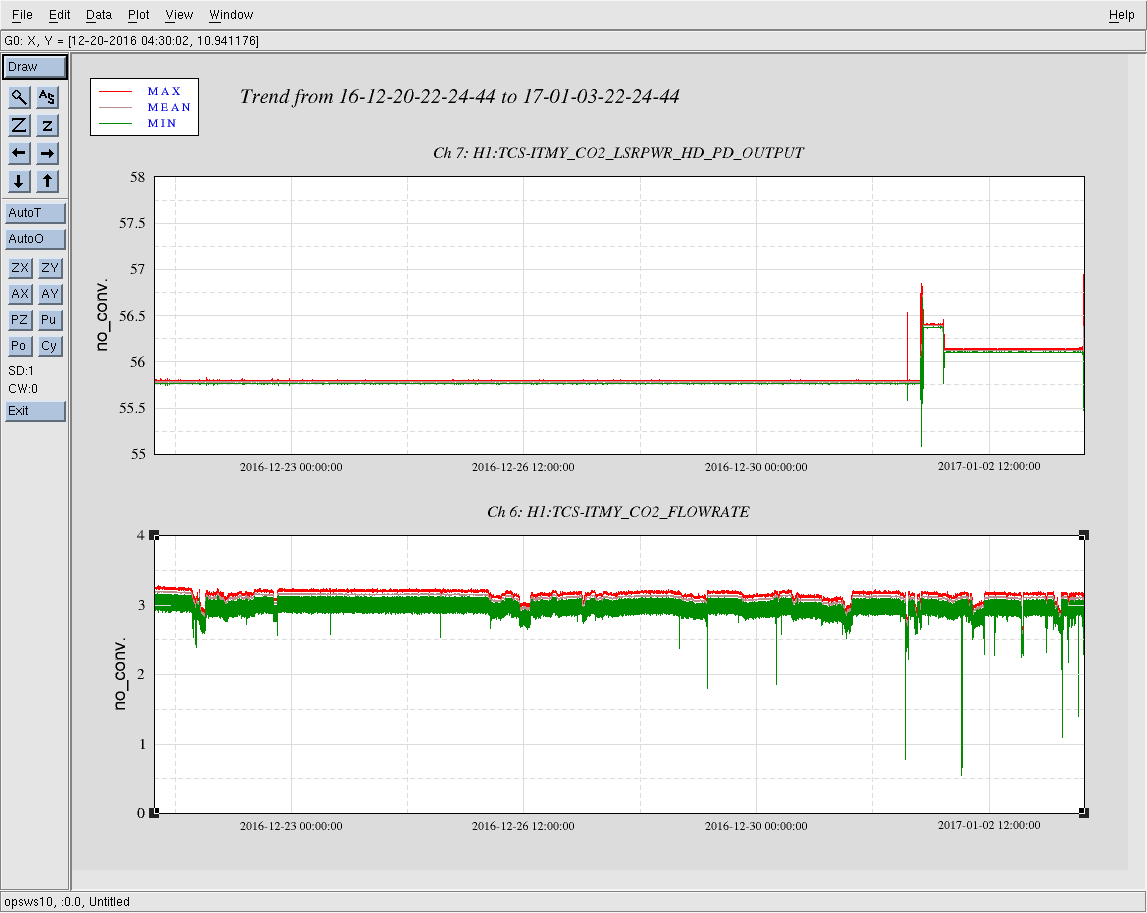
It might be a good idea to try swapping the laser controller chassis next. The electronics path for this flow meter is very simple - just the controller and then into the EtherCAT chassis where it's read by an ADC.