nutsinee.kijbunchoo@LIGO.ORG - posted 05:14, Sunday 20 November 2016 (31660)
Ops OWL mid-shift summary
Still locked! 22 hours and counting.
Still locked! 22 hours and counting.
TITLE: 11/20 Owl Shift: 08:00-16:00 UTC (00:00-08:00 PST), all times posted in UTC
STATE of H1: Observing
OUTGOING OPERATOR: Cheryl
QUICK SUMMARY: Been locked for 17 hours and counting.
State of H1: locked 16+ hours
Commissioners: Sheila
Activities:
Note from Sheila:
Gains:
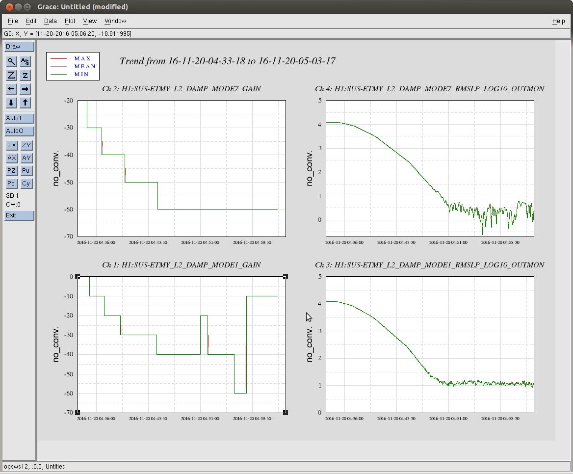
At handoff from Jim he mentioned he'd had to damp ETMY's violins in a long lock recently, so when I got an E_Y saturation I trended it's violin modes 1 and 7 which had been climbing steadily. I looked at the peak in DARM, and it was big, so I went out of Observe to damp the modes.
3:01UTC
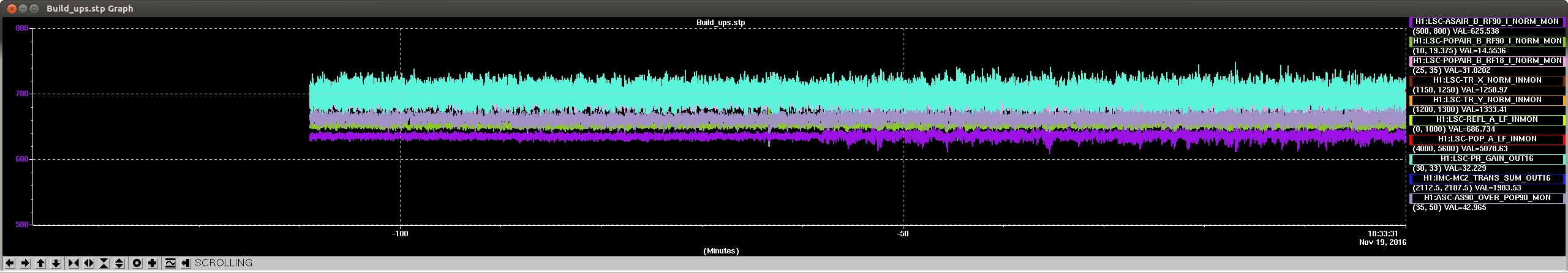
Cheryl and I swtiched to REFL WFS at about 1:34 UTC, and have been locked this way for about an hour without any problems so far. The secondary microseism is around 0.4 to 0.5 um/second, velocities where we previously had trouble switching to REFL WFS. You can see in the attached striptool that the transition did make the AS90 build ups a little less stable.
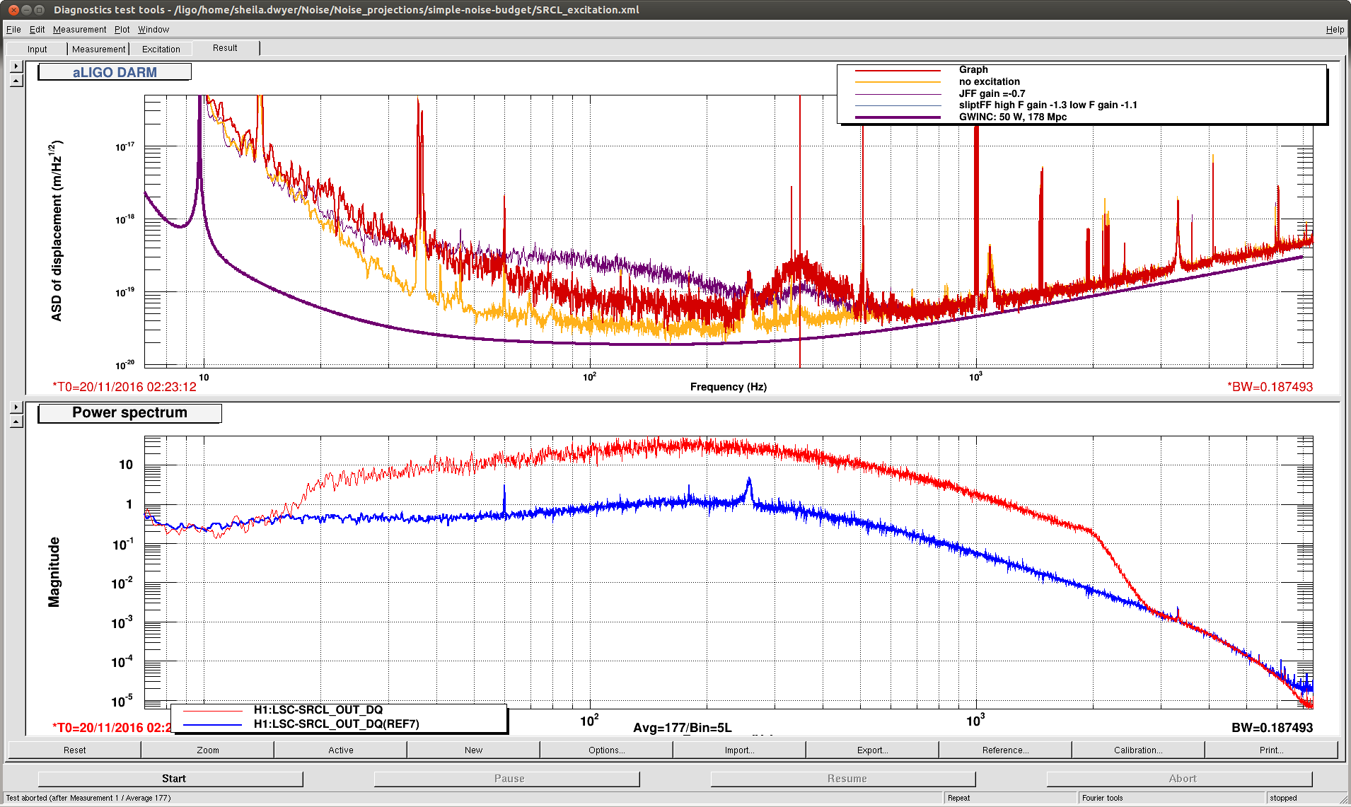
After this was locked for about a half hour, I made some SRCL injections because of the higher SRCL coherence with this new alignment. It seems like we can do better for the noise around 80-100 Hz by using split FF for now, I've put in the gains of -1.1 for the low frequency filter and -1.3 for the high frequency filter. (see attached screenshot) These settings are in the guardain now.
We closed the beam diverters without incident and are ready to go back to observe.
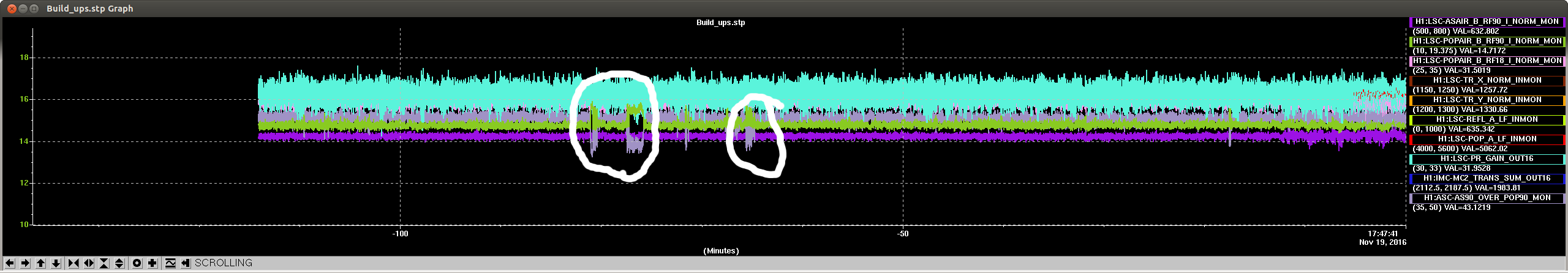
It looks like we had another incident of the POP90 power changing, (circled in the striptool screenshot) similar to what Stefan described in 31181. Is this still a problem with the demod as RIchard found the first time? If its only an intermittent problem with the POPAIR 90 demod, we probably don't need to worry about fixing it before O2 because that is jiust a monitor and won't be used if we are able to close the beam diverters for the run.
Detchar question:
Did we have RF45 glitches around these times? The times are roughly 16:26, 16:30, 16:36 and 16:42 Nov 19th local time, which is 0:26, 0:30, ect Nov 20th UTC time.
We were able to fix some obvious problems with this but the problem with the shield was not changed as we did not test it after the fact.  Though this problem should only appear if someone was in the rack.
Would be interesting to see if anything is on 9,or 45MHz
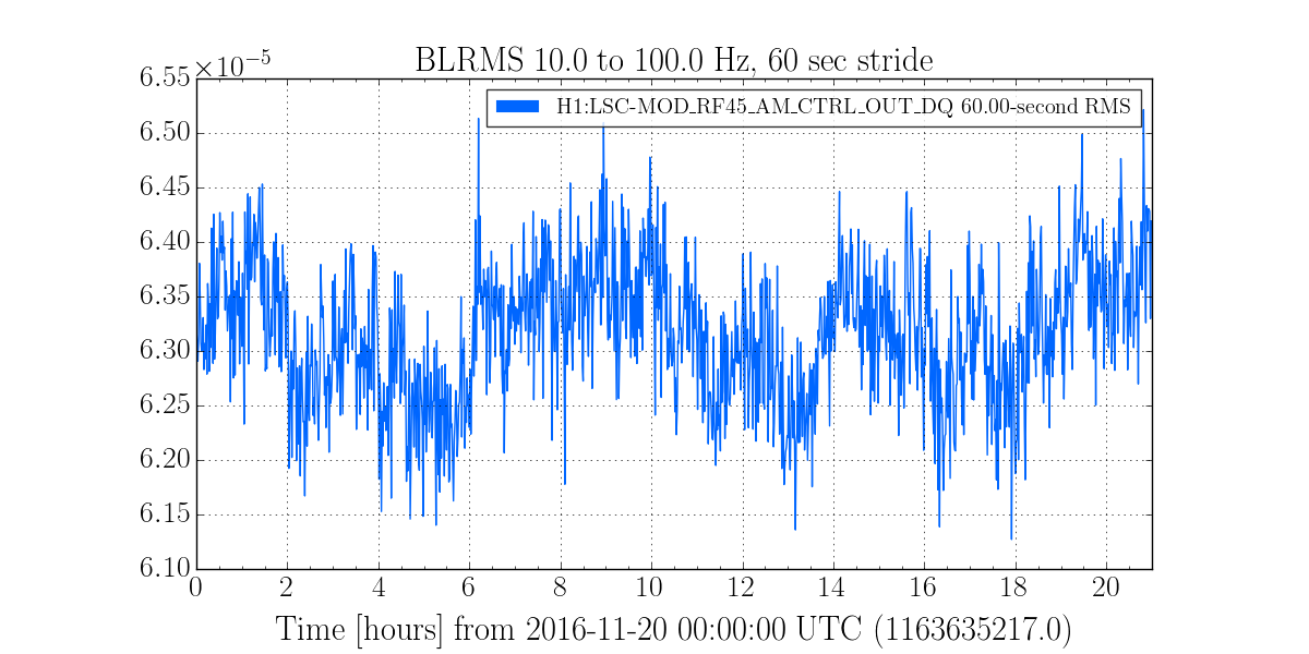
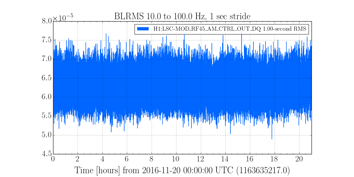
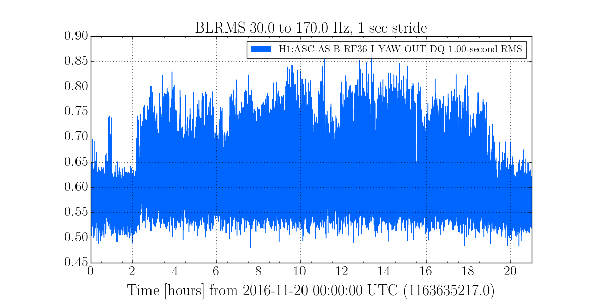
I took at look at the auiliary channels we used to create DQ flags monitoring RF45 noise in O1, namely H1:LSC-MOD_RF45_AM_CTRL_OUT_DQ and H1:ASC-AS_B_RF36_I_YAW_OUT_DQ. I created BLRMS of these channels in the same way we did in O1 to threshold on. In all of these plots we see a steady BLRMS over 21 hours from 20th Nov 00:00 - 21:00 UTC, indicating that these channels do not see any form of RF45 noise we are used to:
* Plot 1 - BLRMS of H1:LSC-MOD_RF45_AM_CTRL_OUT_DQ between 10-100Hz in 60 seconds strides
* Plot 2 - BLRMS of H1:LSC-MOD_RF45_AM_CTRL_OUT_DQ between 10-100Hz in 1 second strides
* Plot 3 - BLRMS of H1:ASC-AS_B_RF36_I_YAW_OUT_DQ between 30-170Hz in 1 second strides
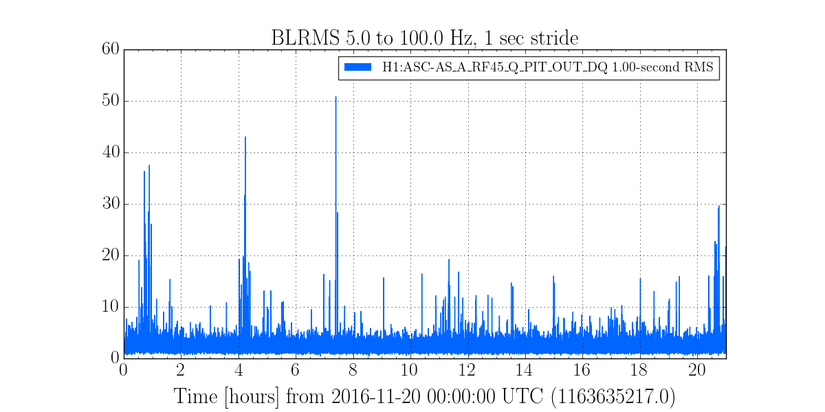
Hveto for this day indicated that H1:ASC-AS_A_RF45_Q_PIT_OUT_DQ was a good channel to veto noise with on Sunday. I therefore did a BLRMS of this channel:
* Plot 4 - BLRMS of H1:ASC-AS_A_RF45_Q_PIT_OUT_DQ between 5-100 Hz in 1 second strides
This channel does show excess noise at certain times of the day. If we were to threshold on this BLRMS using the 99.5% BLRMS value during this time period, we would capture the times Sheila mentions and also veto 8/10 top ten pycbc live triggers for this day.
Not conclusive that this noise is RF45 noise similar to what we saw in O1, investigating further...
Seemingly another incident: circa 2016-11-23 20:25:30 Z.
ITLE: 11/19 Day Shift: 016:00-0:00 UTC
STATE of H1: Observing
SHIFT SUMMARY: Quiet all shift.
LOG:
No commissioners were here, IFO stayed locked since Nutsinee's shift. Microseism is trending up. One Violin mode has been creeping up, 508.585. I've told Cheryl, she'll monitor.
TITLE: 11/19 Owl Shift: 08:00-16:00 UTC (00:00-08:00 PST), all times posted in UTC
STATE of H1: Observing
INCOMING OPERATOR: Jim
SHIFT SUMMARY: I've been skipping CLOSE_BEAM_DIVERTERS afraid that it would cause the lockloss as Sheila reported in alog31635 when the tidal servo wasn't working. I skipped beam diverters during the most recent lock even WITH the tidal servo working, that was just a habit. I could have gone through PR3 REFL WFS step. Tidal servo didn't work most of my shift until I reverted the tidal trigger thresold (see alog31646)
LOG:
11:19 Ran a2l and went to Observe
12:58 Verbal alarm outputs OMC DCPD Saturation followed by lockloss.
14:17 Another Lockloss. CARM ran away.
15:15 At DC_READOUT. Following procedure from Terra's alog 31593. Turned off PI gains.
15:17 Turned PI gains back on, then run a2l. Sorry I read instruction in wrong order. It's late for me.
15:22 a2l done. Zeroed all PI gains and moving on.
15:31 Running another a2l at NLN. PI gains are still 0.
15:37 a2l done. Set intent bit.
15:48 -3000 gain to PI mode 28
15:49 +5000 gain to PI mode 27
15:51 +3000gain to PI mode 26
15:53 -5000 gain to PI mode 27, then flipped back to 5000
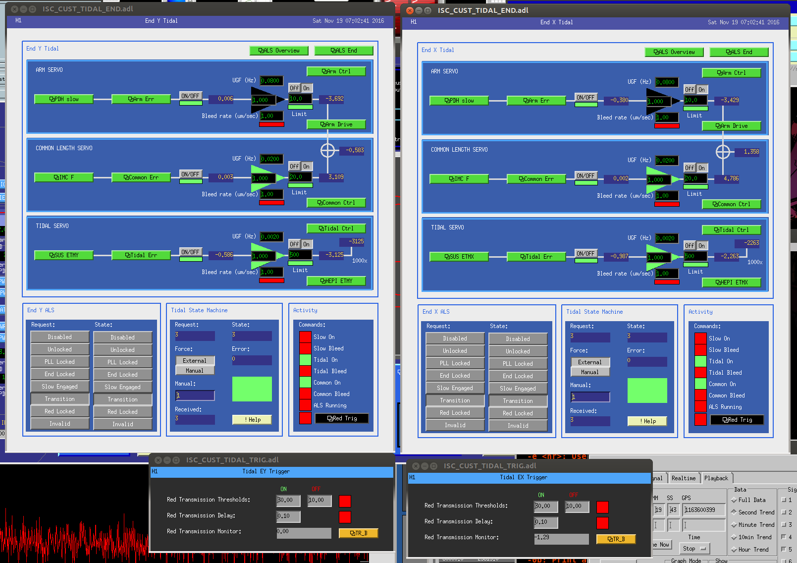
I suspect this is the result of the broken tidal servo?
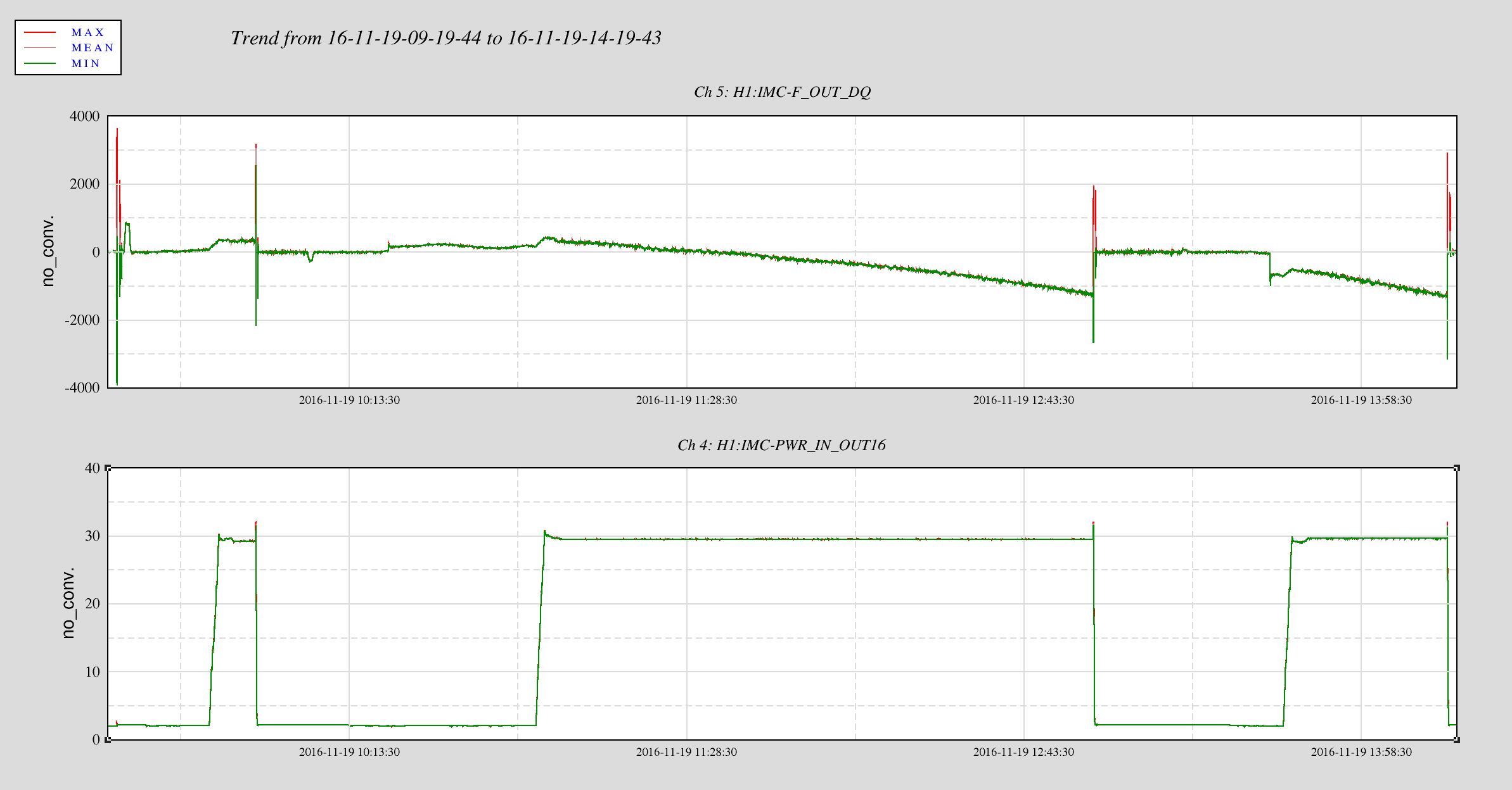
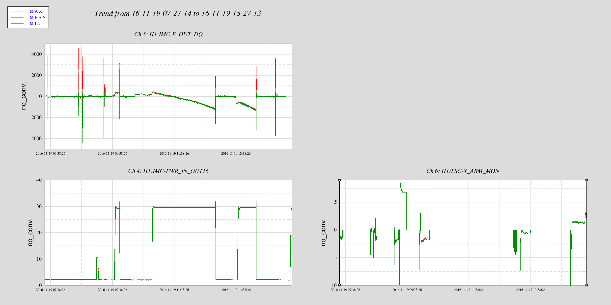
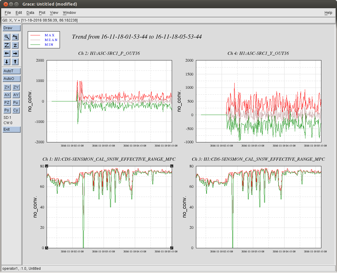
I reverted the REDTRIG on/off threshold back to where they were 2 days ago. I can see some outputs now. The threshold were set to 8000 (ON) and 5000 (OFF) previously (as mentioned in alog31573). Below I attached a plot showing LSC-X_ARM_MON being 0 through the entire two lock stretches.
TITLE: 11/19 Owl Shift: 08:00-16:00 UTC (00:00-08:00 PST), all times posted in UTC
STATE of H1: Initial Alignment
OUTGOING OPERATOR: Cheryl
QUICK SUMMARY: Cheryl reported issue DRMI ASC (PRC and SRC ran away?) so she was doing an initial alignemt. Since the alignment hasn't been changed I wanted to see for myself so I let ISC_LOCK take control and try again (making measurement for Sheila in the process). X arm green couldn't get to 0.9 so I moved ITMX and TMSX (knowing it's probably be terrible for the michelson). PRMI indeed looked terrible so I went back to Initial alignment to take care of the corner station optics. I just finished the green arms. Beatnote was terrible for so I moved PR3.
Sheila, Nutsinee
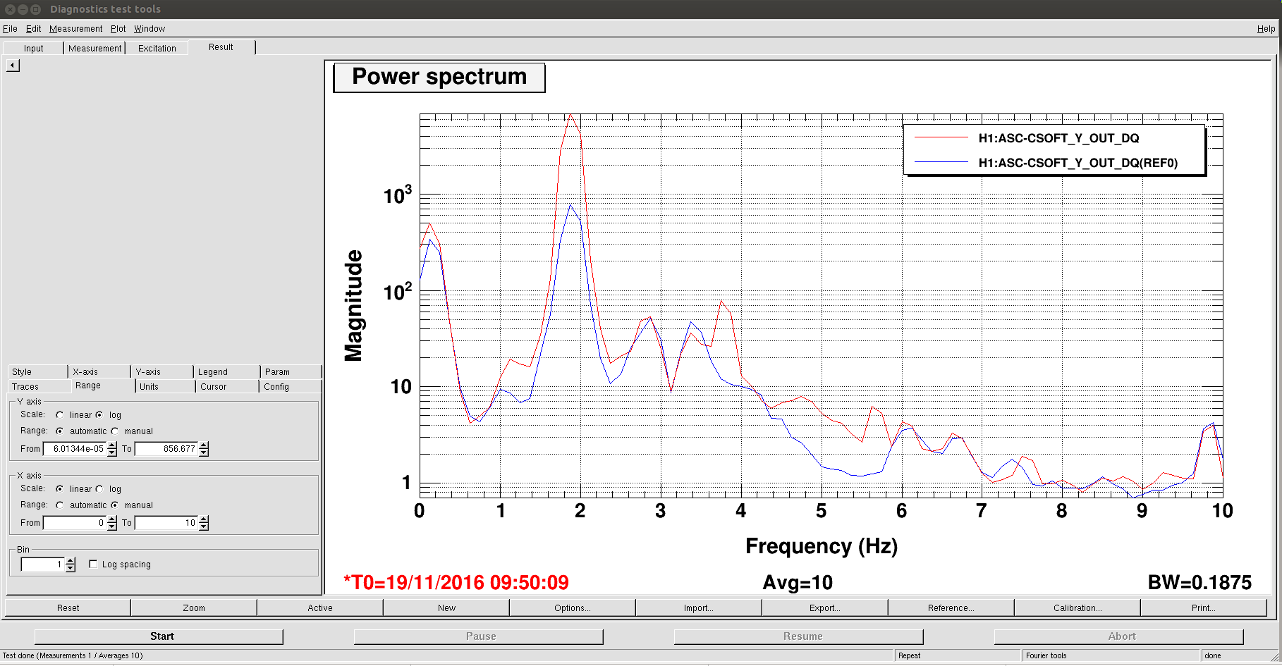
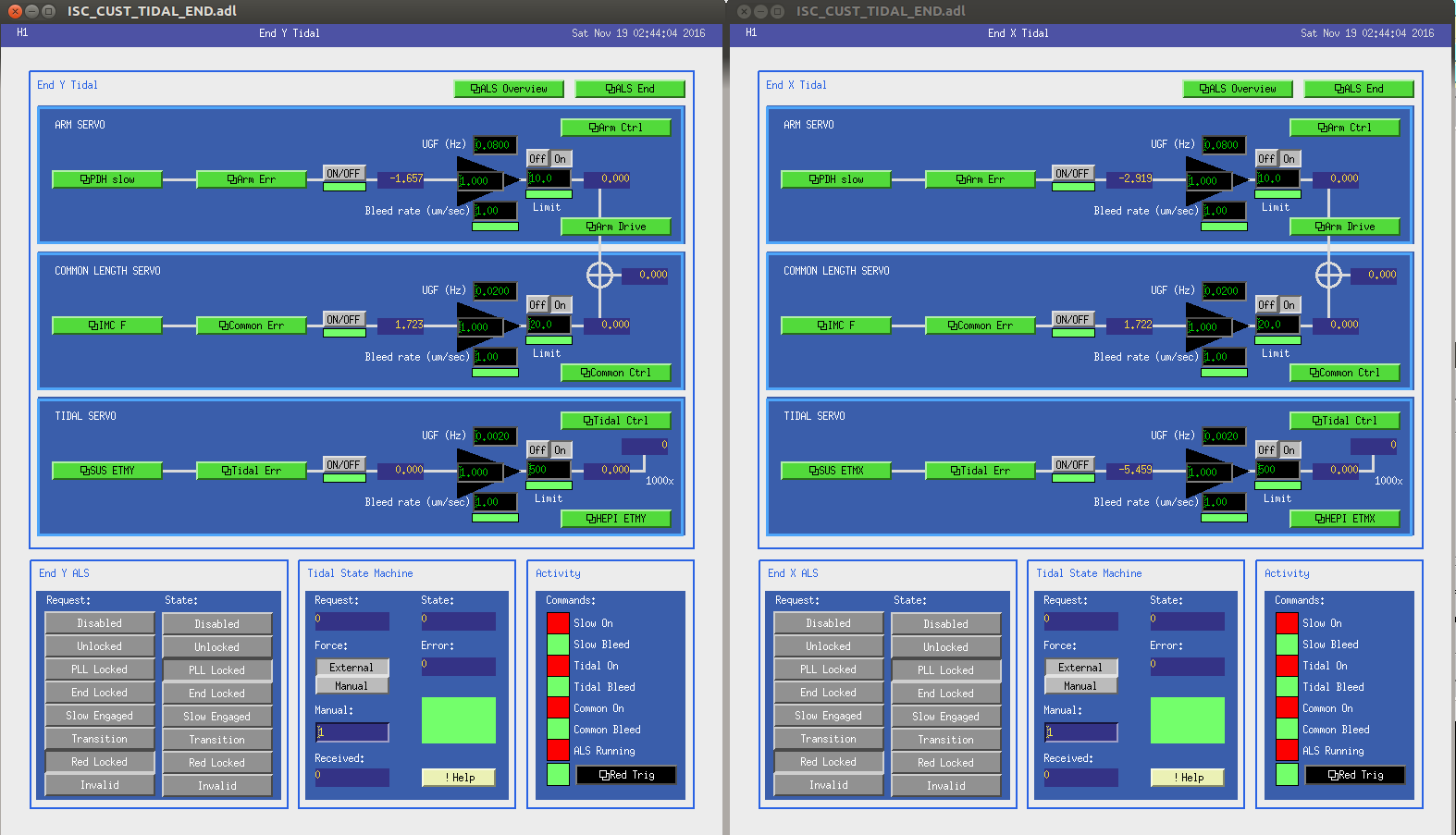
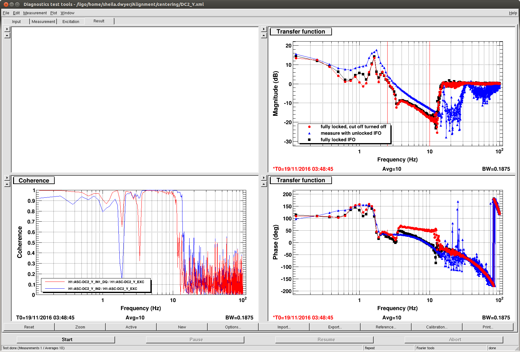
Broke lock while sitting at Noise Tuning trying to figure out if Tidal servo really came on (noticed IMC_F_OUT16 went off from 0). Prior to the lockloss the most obvious ranaway signal was CSOFT Yaw (at 2Hz -- Sheila said it's DC1 Yaw instability). Then relocked and stopped at DC readout to figure out the tidal thing again. Tidal is not on. There seems to be signal going in but nothing comes out. We don't know how to make it turned on. I also attached the DC1Y centering loop measurement at DC readout.
I skipped PR3_REFL_WFS and CLOSE_BEAM_DIVERTERS abd landed at SET_REF_POWER because Sheila reported that close beam diverter caused a lockloss when tidal didn't come on. Apparently I'm not supposed to land there since there's no path to NLN. I manually went to NLN. Jitter noise looks worse than last night. BNS range also seems worse.
I was told to turn off all the PI damping at DC readout. This is a bad idea. The three usual modes rung up within 10 minutes into the lock and I ended up have to damp all three mode at once. I'm not turning the gains off for the rest of the night.
For zeroing of PI gains, see Terra's alog 31593, and the Ops Sticky Notes.
State of H1: locking DRMI but cannot engage DRMI ASC
Commissioners: Sheila, Terra, Daniel
Activities:
Notes from Sheila:
Notes from Terra:
My damping of PIs:
Correction: Terra's alog 31593 instructs us to zero modes 3 and 26 to zero:
"Whoever is in the chair next when we have to relock (days from now I'm sure...), please:
• Stop at DC Readout. Run a2l. Turn PI Mode 3 & 26 gain to zero. Record time in alog when you put gains to zero.
• Continue up as normal."
We've been struggling to switch from POP X to REFL WFS, probably because with our low recycling gain we are near the point where the REFL WFS have a sign flip for PR3. However, we know that we get bad scattered light coupling to DARM from ISCT1 if we leave the beam diverters open, so it would be good to switch to REFL WFS. TOday and last night we tried improving the recycling gain by changing the spot position on PR3, which makes the broad lump of noise from 200-1kHz come back. We also have reduced range which is probably because the SRCL coupling changes and we need to update the feedforward. I am hoping that we can see that the interferometer is stable in this configuration, and that we can get the range back to 75Mpc by retuning the FF if we get a long lock to measure the transfer function. In that case we will have to decide if we are more bothered by jitter or the scattered light, or try jitter subtraction or TCS to help with the jitter.
One wrinkle in this is that the REFL WFS centering for yaw seems to go unstable, probably because it is cross coupled with some of our ASC loops. If you are an optimist you will believe this was actually the problem with the REFL WFS not the changing matrix, and that we can just go back to our low jiter/ low recycling gain alignment.
Move PR3 spot position:
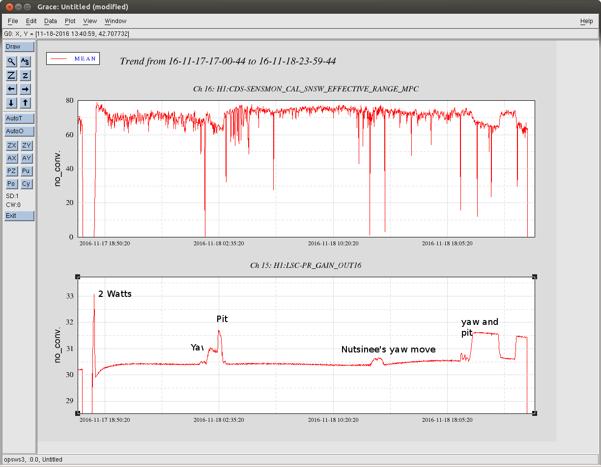
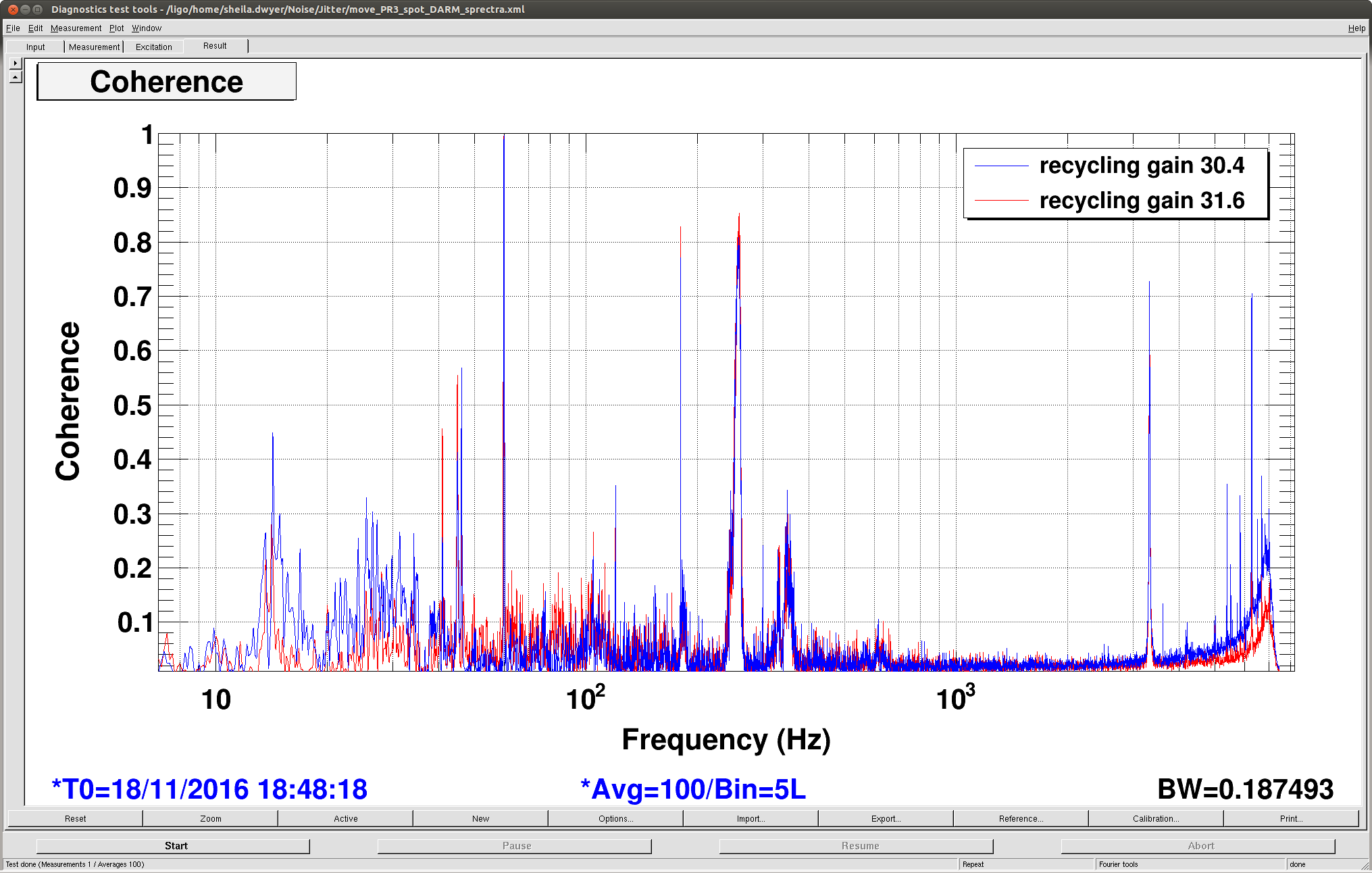
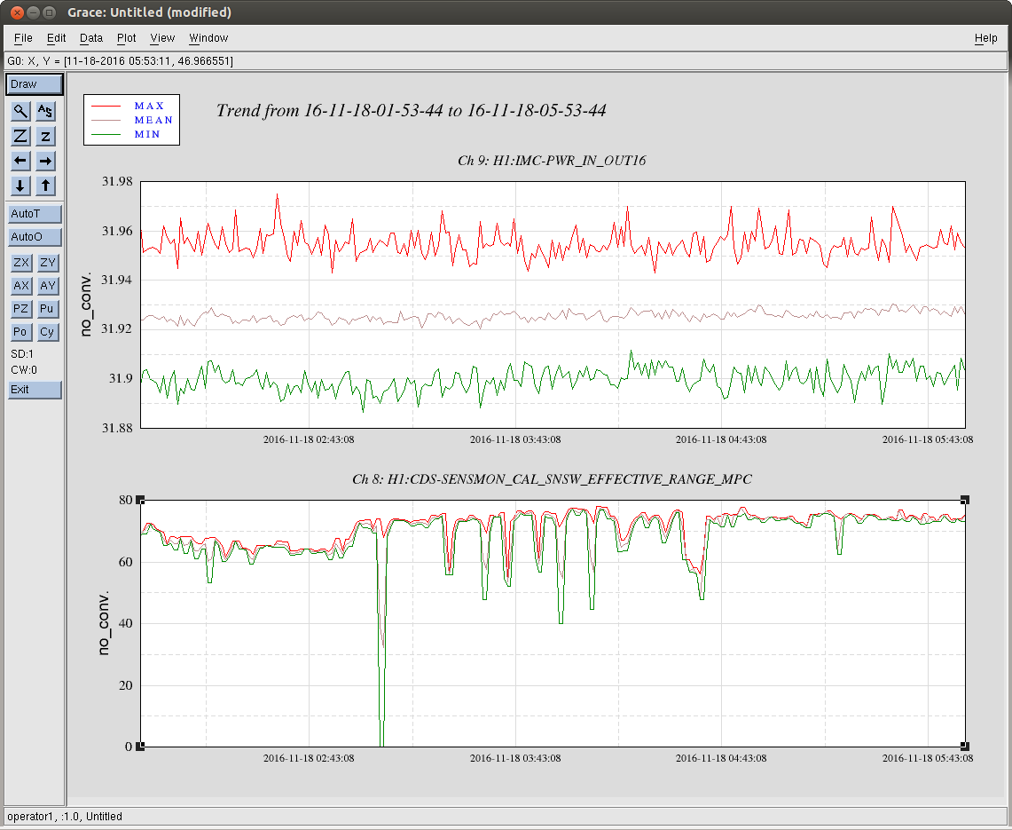
Yesterday we tried moving our spot position on PR3 as a way of increasing the recycling gain. We have been operating at an alignment that gives us a recycling gain of around 30.5, but minimizes the broad jitter lump in DARM. We are able to get a modest increase in recycing gain (to almost 30.7) by moving the PR3 spot in yaw, without causing any extra noise in DARM (this is the test that Nutsinee did last night). However, to get the best recycling gain (almost 31.6 ish) we need to also move pitch back in the direction that makes the broad jitter lump appear again. The first attachment shows the range and recycling gain over the course of the 30 hour lock we just had, you can see that the range clearly drops when the recycling gain increases.
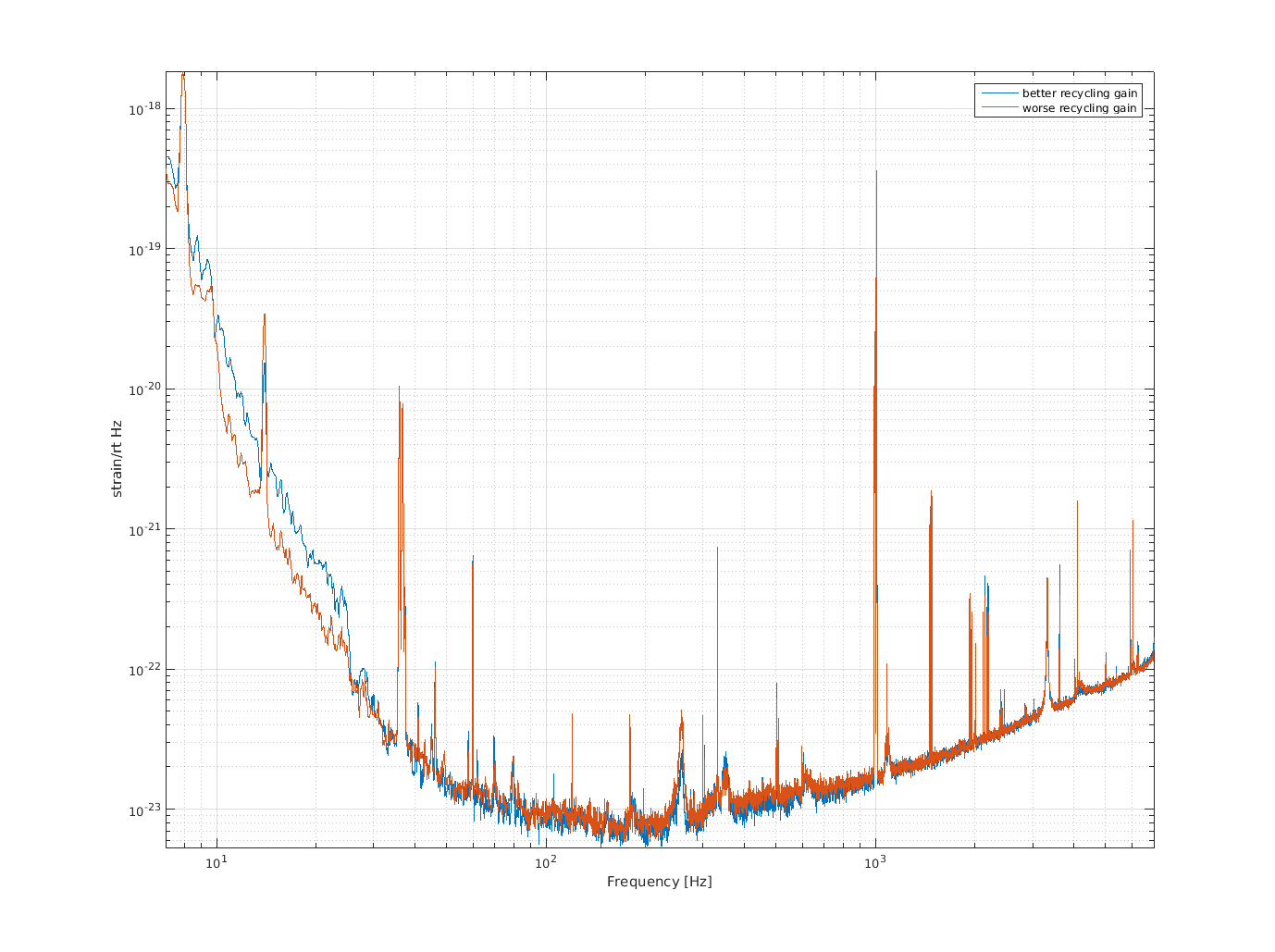
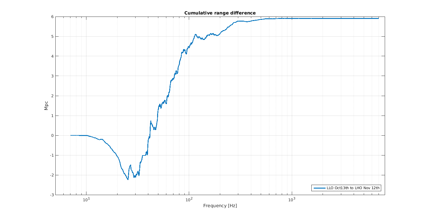
The drop in range however is not due to the jitter peaks, but due to the very small change in the noise from 30-200Hz. The second attachment is a comparision of the spectra in these 2 configurations, in the good recycling gain example we had not retuned a2l which makes the noise below 25Hz bad in the blue trace. The third attachement shows the cumulative range difference, you can see what frequencies are responsible for the drop in range. The third attachment shows that in the higher recyclcing gain state we had more SRCL coherence at these frequencies, so it might be possible to recover the range with the higher recycling gain by retuning SRCL feedforward.
The offsets to use in PRC1 to get to the recycling gain of 32 are 0.2 for pit and -0.109 for yaw. I have put these into the POP A offsets, old values were 0.44 for yaw, nothing for pit, new values are 0.2 for pit, 0.331 for yaw. Cheryl was able to lock the interferometer this way without any updating of the inital alignment references.
PR3 on REFL WFS:
This afternoon I measured the refl WFS sensing for PR3 in some uncalibrated units:
| recycling gain 30.4 | recycling gain 32 | |
| A9I pit | 0.572 | 1.12 |
| A45I pit |
0.036 |
0.26 |
| B9I pit |
0.94 |
1.478 |
| B45I pit | -0.6 | -0.642 |
| A9I yaw | -0.367 | 0.065 |
| A45I yaw | 0.026 | -0.352 |
| B9I yaw | 0.795 | 1.232 |
| B45I yaw | -0.462 | -0.407 |
I used the signals for which there is a signal with the same sign in both measurements and not factors of 10 gain changes.
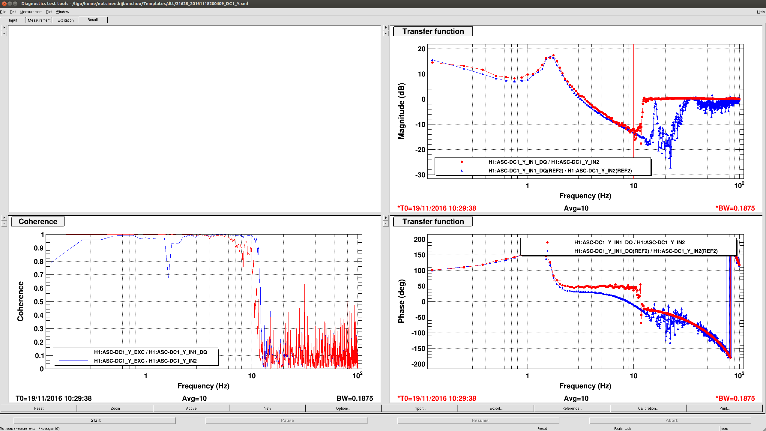
I used an input matrix of 0.53 for REFL A 9I, 0.04 for REFLB9I and -0.092 for REFL B45I. For yaw I switched it over using an input matrix of just refl B, 0.066 REFLB9I and -0.2 REFLB45I. This gives us a ugf about a factor of 4 below what we use for POPX. We have an instability at around 1.88 Hz when we sitch yaw over to REFL WFS with a higher bandwidth, I think it comes from the DC1_Y centering loop.
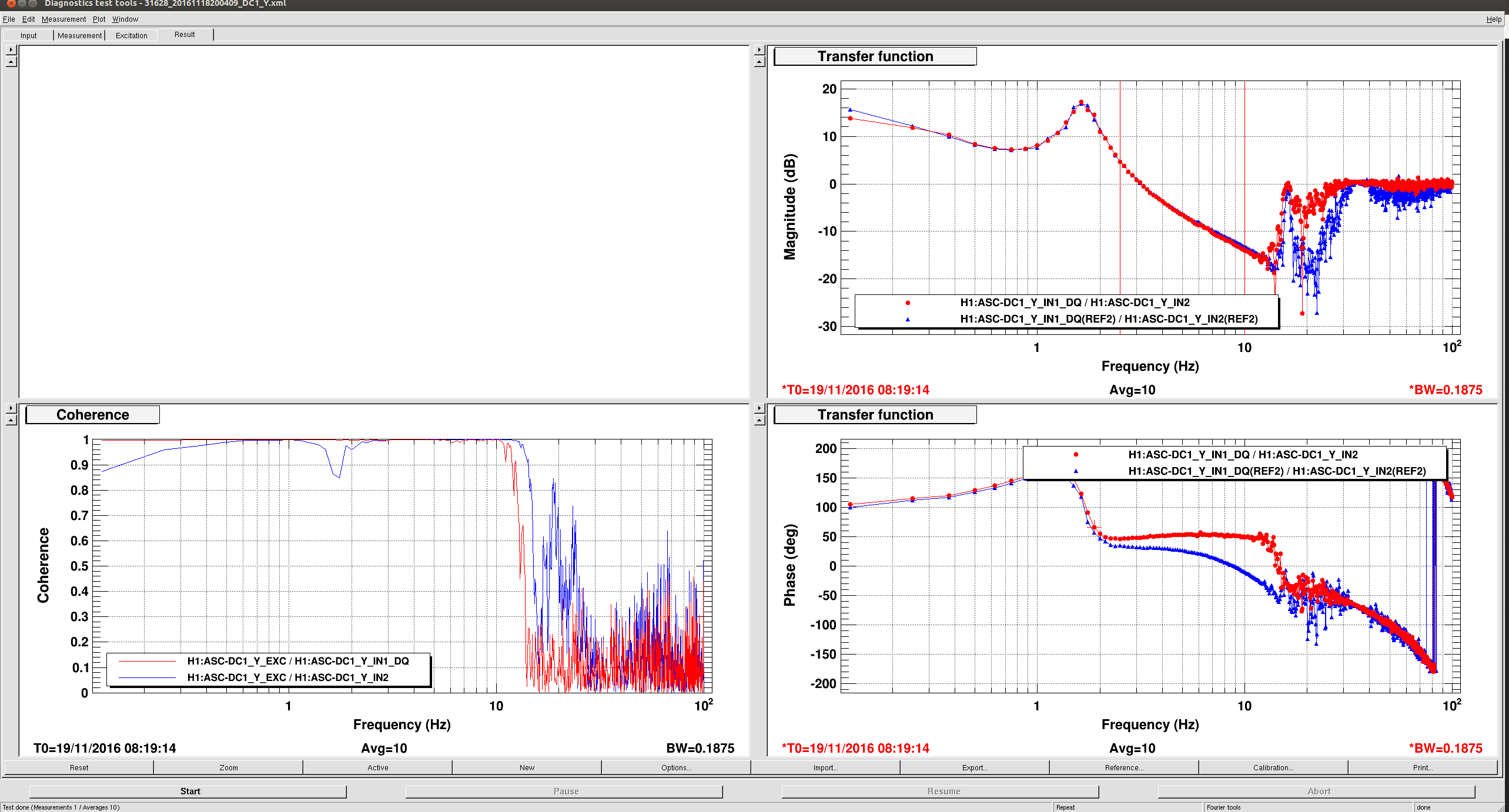
DC1Y centering instability:
Last week Daniel and I worked on the refl centering loops with the interferometer off, (31382), the settings haven't changed but when I measured DC1Y with the full interferometer locked, something has changed for the worse as shown in the 5th attached screenshot. One gues is that this is because the centering loops are cross coupled with our other ASC loops.
We can try to fix this by increasing the gain, for now I have removed the cut off filter from DC1Y, which only helps a little. Having this off causes RM2 to saturate when we are locked at DC readout (the talker announces this as OM). I also added a notch to PR2Y which only gets engaged when we switch to the REFL WFS, it would not be OK if we had a higher bandwidith. This isn't a very good solution.
The guardian is edited to put in the new matrix and engage the notch for now in PR3_REFL_WFS. If this is not stable you can just go back to skipping PR3_REFL_WFS and CLOSE_BEAM_DIVERTERS
Operator Request: If the interferometer unlocks, could whomever is on shift measure the DC1Y centering loop?
Came to find Cheryl attempting an initial alignment but she reported that no alignment has been changed since the last lock. I let the ISC_LOCK Guardian take control again and did the measurement. I reverted the set up (turn input off for DC1 and 2, aligned ITMs and ETMs) then moved on to locking
.
And one more at DC_READOUT

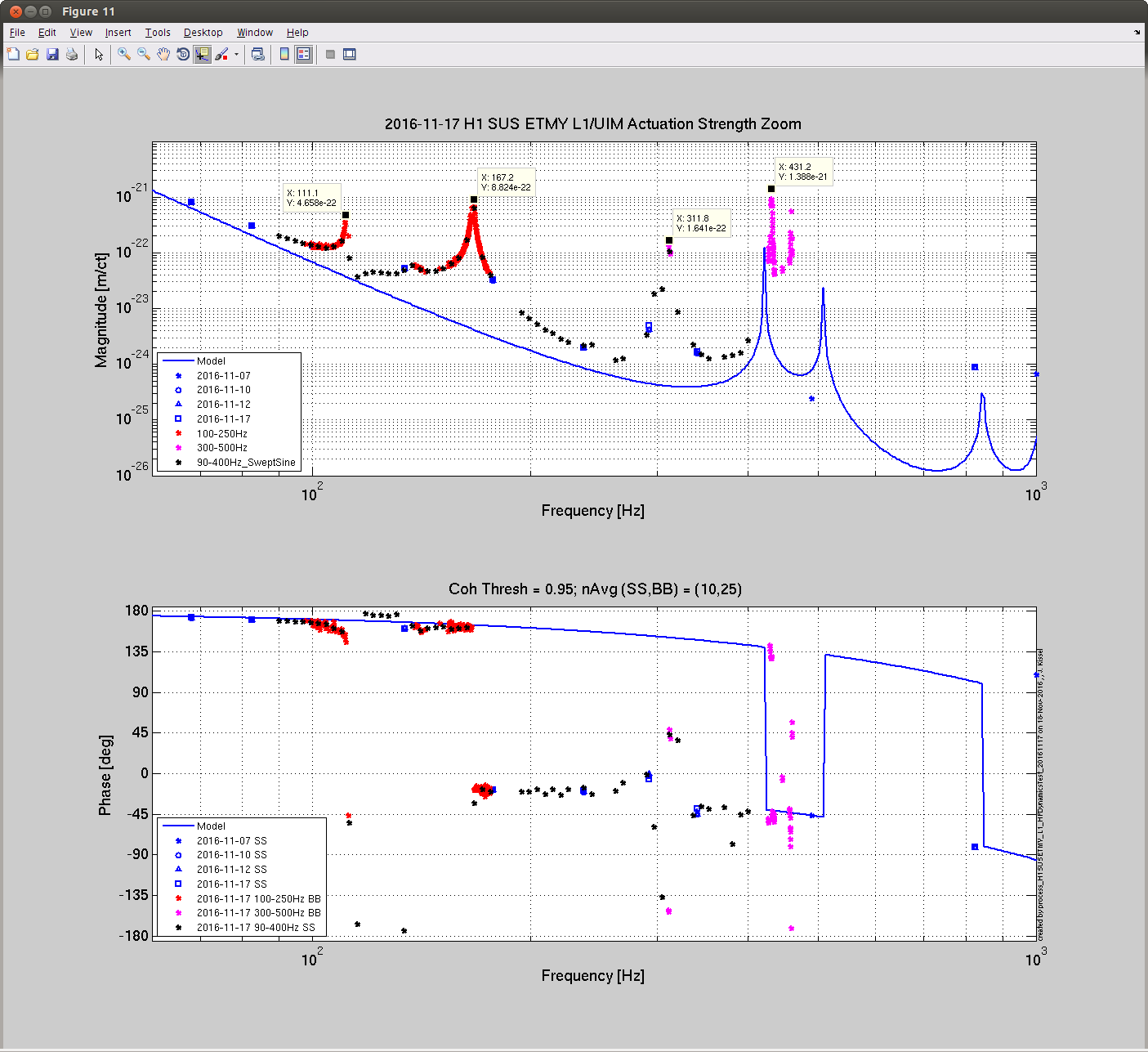
J. Kissel, D. Tuyenbayev

Analyzing the high-frequency data for the UIM that we took last night (LHO aLOG 31601), we find -- as previously suspected -- there is lots of dynamical resonant features in the UIM / L1 actuation stage; it definitely does NOT fall as f^6 to infinity as one might naively suspect.

There are even more features than the (now anticipated; LHO aLOG 31432) broad impacts of the violin modes of the Sus Point-to-TOP wires (~311 Hz), and UIM-to-PUM wires (~420 Hz). We had seen hints of these features previously (LHO aLOG 24917), but here they are fully characterized out to 500 Hz with a combination of swept-sine (SS) and broad-band (BB) transfer function ratios (the calibration standard measurements of PCAL2DARM = C / (1+G) and iEXC2DARM = C A_i / (1+G)). The measurements yield the actuation strength of the UIM stage, in terms [m] of test mass displacement per [ct] of drive from the L1_TEST_L bank, which is the Euler-basis equivalent to DAC [ct]. To scale to [m/N], is a mere scale factor, measured to be
     20/2^18 [V/ct] 0.62e-3 [A/V]* 1.7082 [N/A] = 8.08e-8 [N/ct] (see LHO aLOG 31344).


Via private communication in January this year, Norna suspects that 111 Hz feature is the first internal mode of the UIM blades, backed by a bench test of the blades at CIT which revealed a resonance at 109 Hz. No ideas on the 167 Hz mode though.

These high frequency dynamics continue to plague the estimate of the UIM actuation strength at DC using the traditional frequency-dependent sweep method, because these high frequency dynamics begin to affect the actuation strength at as low a frequency as ~30 Hz (LHO aLOG 31427), and any model fitting code gets totally distracted by these features.

A challenge to the CSWG team: fit this transfer function above 20 Hz and create a set of zeros and poles that can be used as a "correction" filter to a model that falls off as f^6. This filter need not perfectly resolve the details of all of the high-Q features, but it must track the overall frequency dependence over the 20 - 500 Hz region well. I attach all of the measurements compressed onto one (discontinuous) frequency vector as an ascii in the standard DTT form of [freq re(TF) im(TF)]. To use:
    >> foo = load('2016-11-17_H1SUSETMY_L1_Actuation_HighFreqChar_asciidump.txt')
    >> figure; loglog(foo(:,1), abs( foo(:,2)+1i*foo(:,3) ))
This data is also committed to the CalSVN repo here:
    /ligo/svncommon/CalSVN/aligocalibration/trunk/Runs/ER10/H1/Results/Actuation/2016-11-17_H1SUSETMY_L1_Actuation_HighFreqChar_asciidump.txt
Kiwamu has already tried to create such a filter from the previous data (LHO aLOG 28206), but was limited by  that measurement's high-frequency bound falling between the 111, 137, and 167 Hz features.

Details:

Analysis code:
    /ligo/svncommon/CalSVN/aligocalibration/trunk/Runs/ER10/H1/Scripts/FullIFOActuatorTFs/process_H1SUSETMY_L1_HFDynamicsTest_20161117.m

Config files:
    IFOindepPars = '../../../Common/params/IFOindepParams.conf';
    IFOdepPars   = {'../../params/H1params.conf'};
    IFOmeasPars  = {'../../params/2016-11-12/H1params_2016-11-12.conf'};
    PCALPars = {'../../params/2016-11-12/measurements_2016-11-12_ETMY_L1_actuator.conf'};

Model:
    /ligo/svncommon/CalSVN/aligocalibration/trunk/Runs/O2/DARMmodel/src/computeDARM.m

Will post the data for the fitting challenge later this afternoon.
I made an update to the quad matlab model to account for these mystery features. See CSWG log 11197.
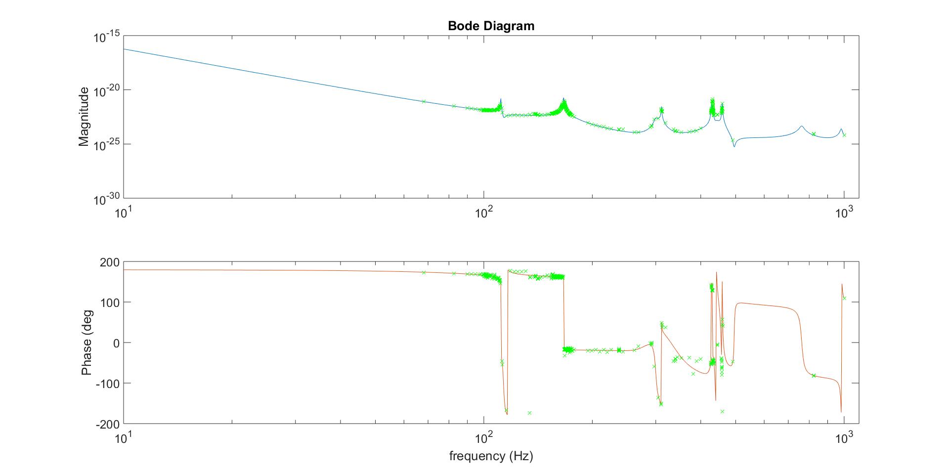
I describe my use of the Frequency Domain System Identification toolbox (FDIDENT) to fit this transfer function in CSWG elog #11205. FDIDENT is a third party Matlab toolbox which provides tools for identifying linear dynamic single-input/single-output (SISO) systems from time response or frequency response measurements. The toolbox is free for non-profit use.
https://www.mathworks.com/products/connections/product_detail/product_35570.html
http://home.mit.bme.hu/~kollar/fdident/
A stable, but non-minimum phase, model without delay – compatible with a Linear Time Invariant (LTI) representation -- results in a best fit for a 22 order numerator and 28 order denominator model, m2228. The model is compared to the measurement data in the attached bode plot.
I attach several new parts of this high frequency characterization in order to facilitate incorporating the uncertainty in any future transfer function fitting.
I attach three new text files:
"..._tf.txt" -- a copy of the originally attached text file, columns are
[freq re(A) im(A)]
"..._coh.txt" -- an export of the (prefiltered) coherence, columns are
[freq iEXCCoh PCALCoh]
"..._relunc.txt" -- an export of the combined relative uncertainty on the transfer function, columns are
[freq sigma_A]
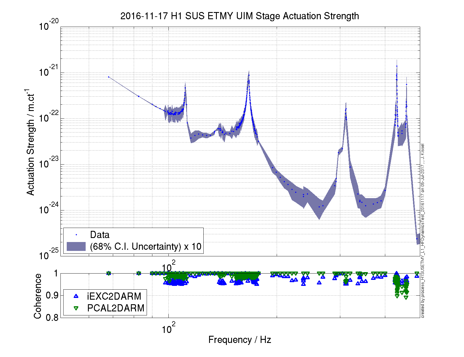
Computing the uncertainty on this actuation strength was a bit of a challenge.
Remember, the above measure of the actuation strength of the UIM stage, A, is a combination of two transfer functions, as described in P1500248, Section V. In this aLOG they're referred to as "PCAL2DARM" where we use the photon calibrator as a reference actuator, and "iEXC2DARM" where the suspension stage under test is used as the actuator. Typically, the iEXC2DARM transfer function has the lowest coherence.
Even worse, I've combined many data sets of both transfer functions covering different frequency regions each with a different number of averages.
Thus form the uncertainty, I've taken each frequency region's data set, and
- Filtered both iEXC and PCAL transfer functions for data points in which the iEXC TF has coherence greater than 0.95,
- Created a relative uncertainty vector for each iEXC and PCAL transfer functions using the standard B&P equation,
sigma_TF(f) / TF = sqrt( (1-C(f)) / (2 N C(f)) )
where C(f) is the coherence, and N is the number of averages (N was 10 for swept sine TFs, 25 for broad band TFs)
- Concatenated the data sets to form the overall transfer function, A,
- Combined the two uncertainty vectors in the standard way,
sigma_A / A = sqrt((sigma_iEXC / iEXC)^2 + (sigma_PCAL / PCAL)^2)
- Sorted the collection of
[frequency complextf iexccoh pcalcoh sigma_A]
by frequency.
- Exported the uncertainty.
Note that one only needs one column of uncertainty, for the absolute uncertainty in magnitude is just
|sigma_A| = abs(A) * (sigma_A / A)
and the absolute uncertainty in phase is
/_ sigma = 180/pi * (sigma_A / A)
I attach a plot of the magnitude and its uncertainty for demonstrative purposes, so that when the files are used, you can compare your plots of this against mine to be sure you're using the data right. Note that I've multiplied the uncertainty by a factor of 10 for plotting only so that it's visible.
I've updated and committed the function that's used to process this data, and it can be found here:
/ligo/svncommon/CalSVN/aligocalibration/trunk/Runs/ER10/H1/Scripts/FullIFOActuatorTFs/
process_H1SUSETMY_L1_HFDynamicsTest_20161117.m
J. Kissel, D. Tuyenbayev

Darkhan and I was able to get another round of calibration sweeps in last night, just after Sheila finished up her alignment test (LHO aLOG 31599). This set is at 31.92 W, with SRC1 Loops Closed -- and the second set of data with the anticipated O2 configuration.

Datasets live here:
Sensing Function:
/ligo/svncommon/CalSVN/aligocalibration/trunk/Runs/ER10/H1/Measurements/DARMOLGTFs
2016-11-17_H1_DARM_OLGTF_4to1200Hz_fasttemplate.xml
/ligo/svncommon/CalSVN/aligocalibration/trunk/Runs/ER10/H1/Measurements/PCAL
2016-11-17_H1_PCAL2DARMTF_4to1200Hz_fasttemplate.xml

Actuation Functions
2016-11-17_H1SUSETMY_L1_iEXC2DARM.xml
2016-11-17_H1SUSETMY_L1_PCAL2DARM.xml
2016-11-17_H1SUSETMY_L2_iEXC2DARM.xml
2016-11-17_H1SUSETMY_L2_PCAL2DARM.xml
2016-11-17_H1SUSETMY_L3_iEXC2DARM.xml
2016-11-17_H1SUSETMY_L3_PCAL2DARM.xml


I'd found that I'd stored the wrong channels in my new templates for the exploration of the UIM/L1 high frequency actuation on 2016-11-12 (LHO aLOG 31433), so I repeated those measurements as well storing the right channels this time:
2016-11-17_H1SUSETMY_L1_iEXC2DARM_HFDynamicsTest_100-250Hz.xml
2016-11-17_H1SUSETMY_L1_iEXC2DARM_HFDynamicsTest_250-350Hz.xml
2016-11-17_H1SUSETMY_L1_iEXC2DARM_HFDynamicsTest_300-500Hz.xml
2016-11-17_H1SUSETMY_L1_iEXC2DARM_HFDynamicsTest_90-400Hz_SweptSine.xml
2016-11-17_H1SUSETMY_L1_PCAL2DARM_HFDynamicsTest_100-250Hz.xml
2016-11-17_H1SUSETMY_L1_PCAL2DARM_HFDynamicsTest_250-350Hz.xml
2016-11-17_H1SUSETMY_L1_PCAL2DARM_HFDynamicsTest_300-500Hz.xml
2016-11-17_H1SUSETMY_L1_PCAL2DARM_HFDynamicsTest_90-400Hz_SweptSine.xml

Analysis will be posted today (it's finished, we now just need to document it all), and we plan on updating the DARM model and front-end calibration by Monday.

The high-frequency dynamics measurements quoted in this aLOG have been analyzed. See results in LHO aLOG 31603.
J. Kissel, K. Izumi, D. Tuyenbayev,
Overview
Actuation strengths [N/ct] for all three stages have been calculated with MCMC method. In In this analysis we used data from last set of measurements taken on Nov 17 (see above), together with measurements from Nov 7, 8, 10 and 12 (see LHO alogs 31303, 31371, 31403, 31433). The calculated actuation coefficients are:
KU = 8.1648-8 N/ct
KP = 6.844-10 N/ct
KT = 4.395-12 N/ct
The H1DARM model parameters were updated using these values, particularty:
UIM_NpA = 1.739; [N/A]

	PUM_NpA = 0.0334; [N/A]

	TST_NpV2_y = 1.612e-10; [N/V^2]
We will double check the overall DARM loop model, with the updated sensing and actuation, by comparing it to DARM loop TF measurements.
Notice that TST actuation coef came out as a negative quantity, we believe that there is a "-1" missing in the model of this stage.
Details
For this analysis we took each actuation stage to DARM TF and PCALY to DARM TF measurements at the same frequency vector and used only data points with coherences above 0.9, we adopted a Matlab script used at LLO for this part of the analysis (see EvanG's LLO alog 29438). For each actuation stage i, the test point excitation to DARM TF is
iEXC2DARM = Ai,meas * C / (1 + G)
and PCALY to DARM is
PCALY2DARM = C / (1 + G)
The ratio of the two gives:
iEXC2DARM / PCALY2DARM = Ai,meas
Then we divided this my the model of the given stage without the N/ct coefficient, Ai,model / Ki,model = Fi,model, gives measurement of the frequency-independent N/ct coefficient:
Ai,meas / Fi,model = Ki,meas
Then, we used GWMCMC library (https://github.com/grinsted/gwmcmc) for fitting amplitude and phase of the N/ct coefficient for each stage (if the frequency dependent part of the model is correct, then the phase should be 0 deg). The log likelihood function used for fitting is
logLike = log( ∏( 1 / sqrt(2πσi2) exp( - (Ki,meas - Kfit)2/(2σi2) ) )
Fit results for magnitudes are given above and the phases are at the order of 10-3 deg.
The KU, KP and KT coefficients calculated from multiple-frequency transfer function measurements differ from earlier estimations from single line (LHO alog 31344) by 1.7%, 5.3% and 3.1% for UIM, PUM and TST stages. Possibly some unaccounted systematics in the frequency reponses of the DARM model near 35 Hz (the previous analysis was done with the DARM model for ER9).
Izumi K, Kissel J, Tuyenbayev D,
We used ER10 model to re-run an earlier actuation strength analysis using calibrartion line data from Nov 3 - Nov 8 (LHO alog 31344). The original analysis was done with the DARM model in which the positive N/ct sign was used for TST stage actuation, the correct KT sign must have been negative. Below we list the updated results from this single-line analysis, the values are taken from GPS time interval [1162369920 1162413500]:
KU = 8.613 × 10⁻⁸ ± 3.204 × 10⁻¹⁰ N/ct
KP = 6.802 × 10⁻¹⁰ ± 2.254 × 10⁻¹² N/ct
KT = -4.341 × 10⁻¹² ± 1.339 × 10⁻¹⁴ N/ct
Notice this analysis is used as an additional check of the multiple-frequency analysis (see above). The DARM model parameters for ER10/O2 will be based on the multiple-frequency analysis results (refined numbers and comparison results are coming soon).
Izumi K, Kissel J, Tuyenbayev D,
Overview
We calculated the actuation coefficients for the H1 DARM reference time model. For UIM (L1) and PUM (L2) stages the N/ct coefficients were fit based on actuation TF measurements on Nov 7, 8, 10, 12 and 15. These numbers have been reported earlier (see above). The TST actuation strength will have a trend over long time period due to charge accumulation, thus for TST stage it is better to estimate the coefficient based on measurements taken within a short period of time. Since we set the reference sensing function parameters based on measurements taken on Nov 12, for estimation of the TST (L3) stage actuation we decided to use measurements around that date, particularly measurements from Nov 10 and 12.
Contributions from each of the actuation stages to the overall DARM response drops as 1/f6, 1/f4 and 1/f2, for this reason MCMC (and LSQ) fitting were restricted to [0 10] Hz, [0 200] Hz and [0, 200] Hz for UIM, PUM and TST stages respectively.
Below are the resulting N/ct values, these values:
KU = 8.1648 × 10⁻⁸ N/ct (± 0.074% 1-σ)
KP = 6.844 × 10⁻¹⁰ N/ct (± 0.018% 1-σ)
KT = -4.389 × 10⁻¹² N/ct (± 0.031% 1-σ)
And the H1DARM model were updated in the following way (only the N/V2 for TST stage is different from LHO alog 31649):
UIM_NpA = 1.739;         % [N/A]

	PUM_NpA = 0.0334;        % [N/A]

	TST_NpV2_y = 1.6097e-10; % [N/V^2]
New EPICS values used for DARM time-dependent parameters have been calculated with the updated H1 DARM model for ER10/O2 (see attachment 1).
Comparisons
MCMC and LSQ methods gave consistent results, fractional discrepancies between the two were at the order of 10-5 (LSQ fit was done only for magnitude).
Discrepancies between the new values and the ones currently installed in the CAL-CS front-end model are:
UIM: 0.05% (compared 8.1689 × 10⁻⁸ N/ct, the currently installed, old value)
PUM: 0.05% (compared to 6.8407 × 10⁻¹⁰ N/ct)
TST: 3.42% (compared to 4.239 × 10⁻¹² N/ct)
Discrepancies between these values and an updated single-line analysis results (see LHO alog 31668 above) are 5.5% (UIM), 0.6% (PUM) and 1.4% (TST). A larger discrepancy between MCMC and the single-line analysis for UIM, we believe, is mostly due to 5-10% systematic errors in the UIM suspension model at ~36 Hz (see a residual plot attached to Kiwamu's LHO alog 31427).*
Although, the TST stage coefficient was calculated based on Nov 10th and 12th measurements, discrepancies between the values estimated for each of the 5 measurements (Nov 7 - 17), are within 0.5% (see attachment 2).
*Check out Jeff's LHO alog 31603 for more UIM HF investigations.
Details
TST stage fitting plots are attached below (see attachments 3 and 4). UIM and PUM fitting results did not change (see previous report above, LHO alog 31609).
The new EPICS values for DARM time-dependent parameters are committed to
${CalSVN}/Runs/ER10/H1/Scripts/CAL_EPICS/D20161120_H1_CAL_EPICS_VALUES.m
The up-to-date H1 DARM model parameters are commited to CalSVN:
${CalSVN}/Runs/ER10/Common/params/IFOindepParams.conf              r3752

	${CalSVN}/Runs/ER10/H1/params/H1params.conf                        r3826

	${CalSVN}/Runs/ER10/H1/params/2016-11-12/H1params_2016-11-12.conf  r3786
DARM model scripts (SRC detuning TF was modified to include Q-factor at r3814):
${CalSVN}/Runs/O2/DARMmodel/* r3814
Actuation coefficient fitting script was uploaded to
${CalSVN}/Runs/ER10/H1/Scripts/FullIFOActuatorTFs/fitActCoefs_Npct.m r3829
And the results are at
${CalSVN}/Runs/ER10/H1/Results/Actuation/2016-11-20_H1_SUSETMY_*.pdf


