Sheila, Camilla
We can see large SQZ changes dependent on the OPO PZT value, we;vee seen this before, some alignment changes from this PZT should be adjusted for by FC AS and FC beamspot control. The FC beamspot control has been off since the vent, but we're turned FC beamspot control on again in the hope to reduce this dependency.
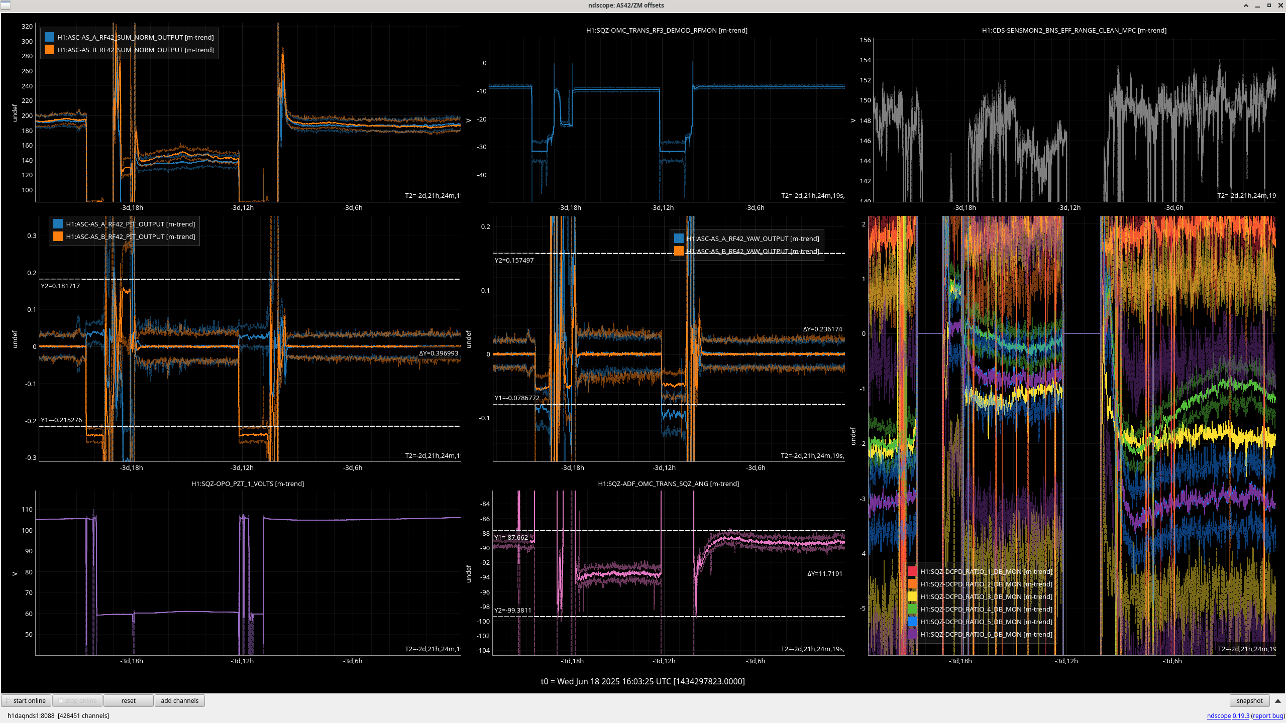
Yesterday we needed to turn the ASC on to improve high freq sqz 85147 and since we've started using the THERMALIZATION guardian 85083 to slowly adjust SRCL Offset, our squeezing and ASC error signals are reduced slightly (see below). We have turned back on the SQZ ASC as expect this new guardian will stop the ASC running away.
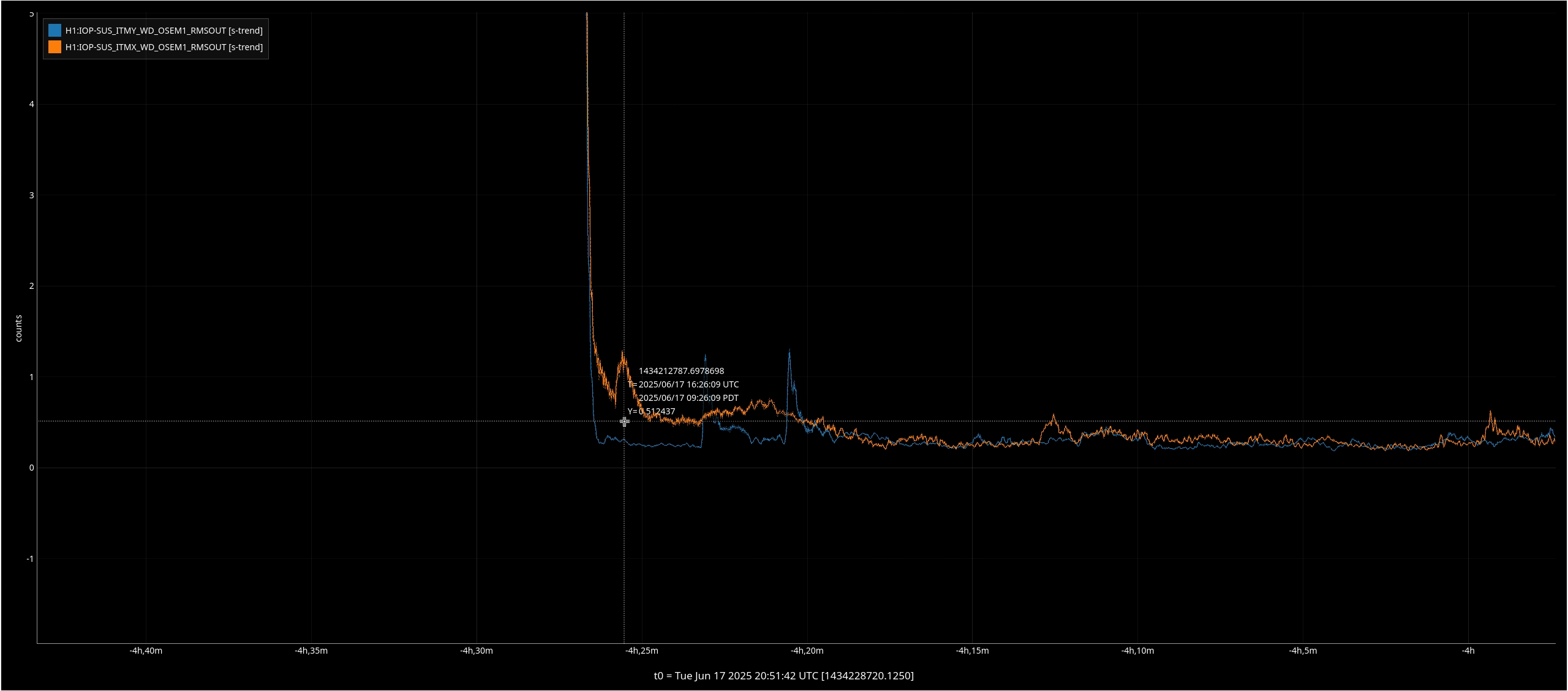
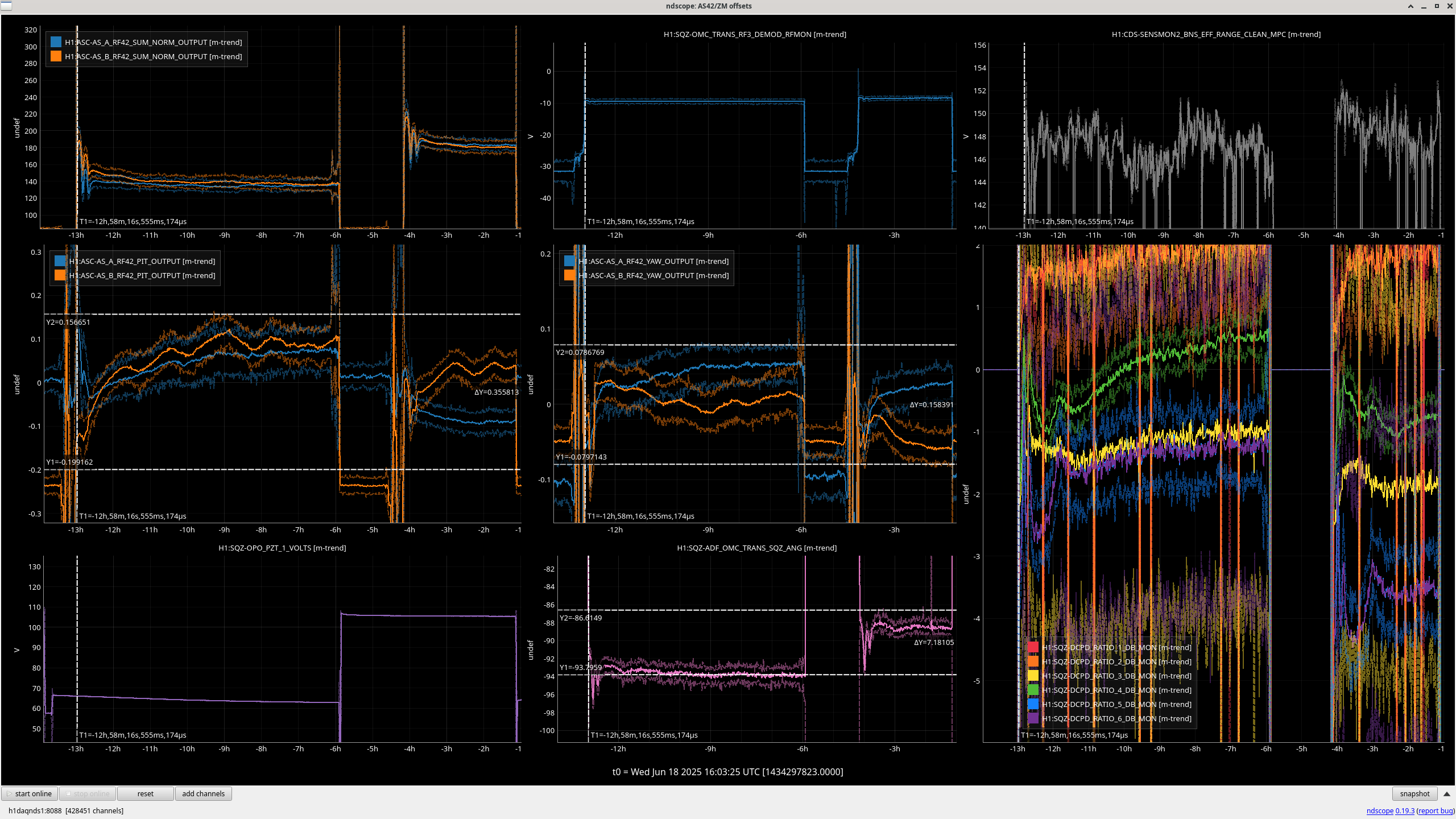
Now we have the THERMALIZATION guardian working, the ADF measured sqz ang change has reduced (see below), we want to try turning back on SQZ_ANG_SERVO which will take a little tuning of settings. You can see in this plot that when the OPo PZT changed, the servo would have adjusted the sqz angle too.
- THERMILIZATION GRD on, SQZ ASC off plot: ASC error 0.35, ADF sqz ang change 7.
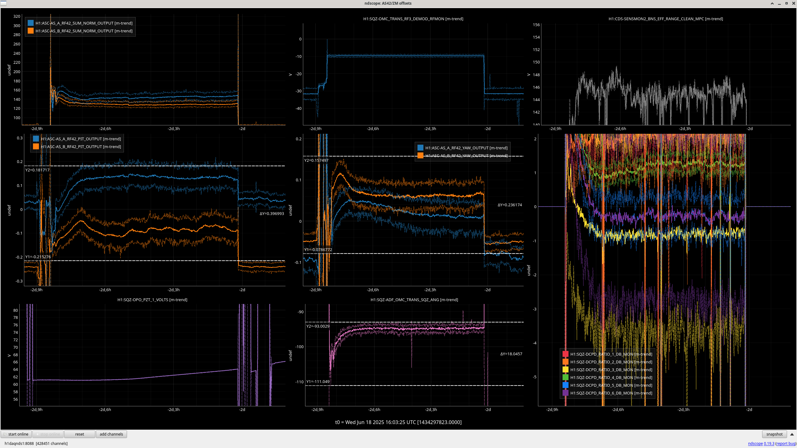
- THERMILIZATION GRD off, SQZ ASC off plot: ASC error 0.4, ADF sqz ang change 18.
- THERMILIZATION GRD off, SQZ ASC on plot: ASC error N/A, ADF sqz ang change 11.
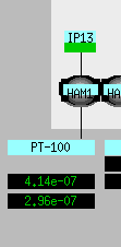
Also touched the SHG launch waveplates to decrease the rejected power in H1:SQZ-SHG_FIBR_REJECTED_DC_POWER.
SQZ ASC was running away at the start of the lock so I've turned SQZ ASC off again.
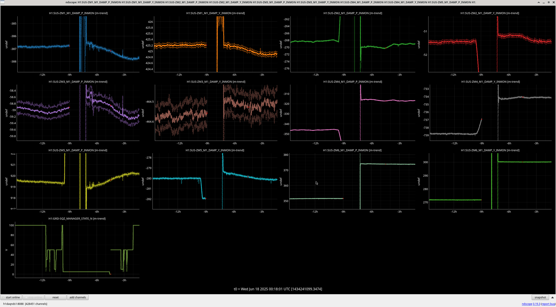
I tried re-measureing the sensing matrix, the result was different to that measrue in September 80373 with the YAW sensor swapped (see output of /sqz/h1/scripts/ASC/python AS42_sensing_matrix_cal.py below) but when I tried it later the sensing matrix seemed to be different, I expect you need to start in good squeezing for it to work well which we were not when I tried it.
Plan to remeasure the sensing matrix more carefully (as in 80373) and then try a new one again.
Also tried today the SQZ_ANG_ADJUST servo using ADF, as the ASC was running away this was confusing, left off.