C. Cahillane
The ER10 LHO Actuation Uncertainty Budget
What has been done:
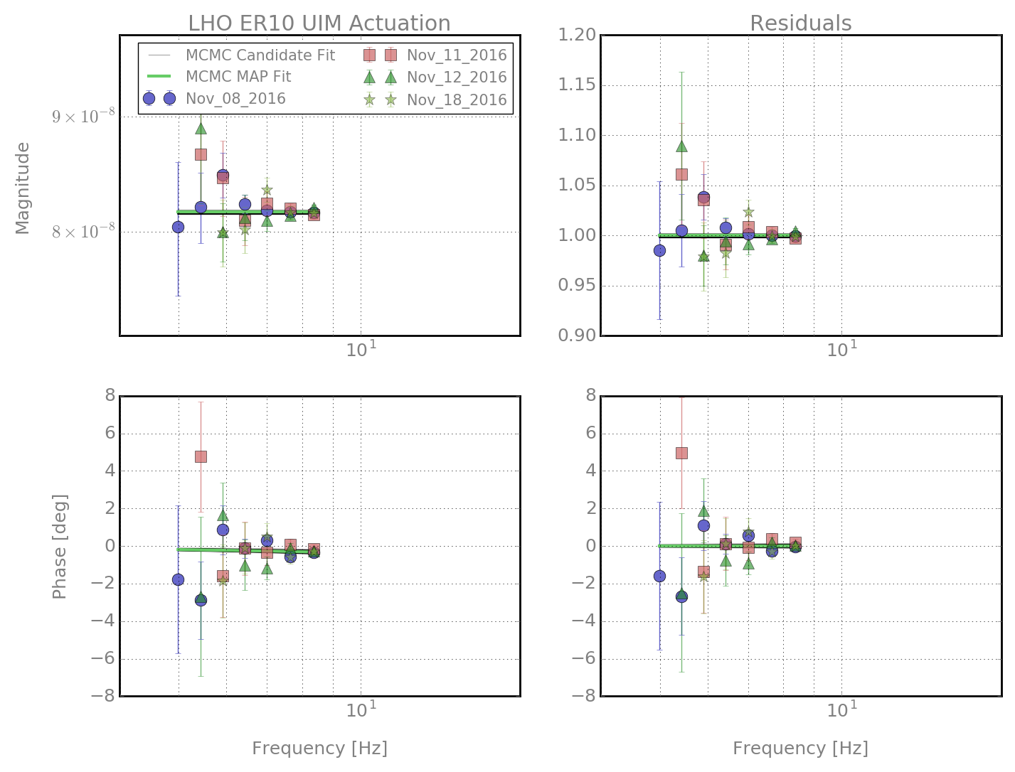
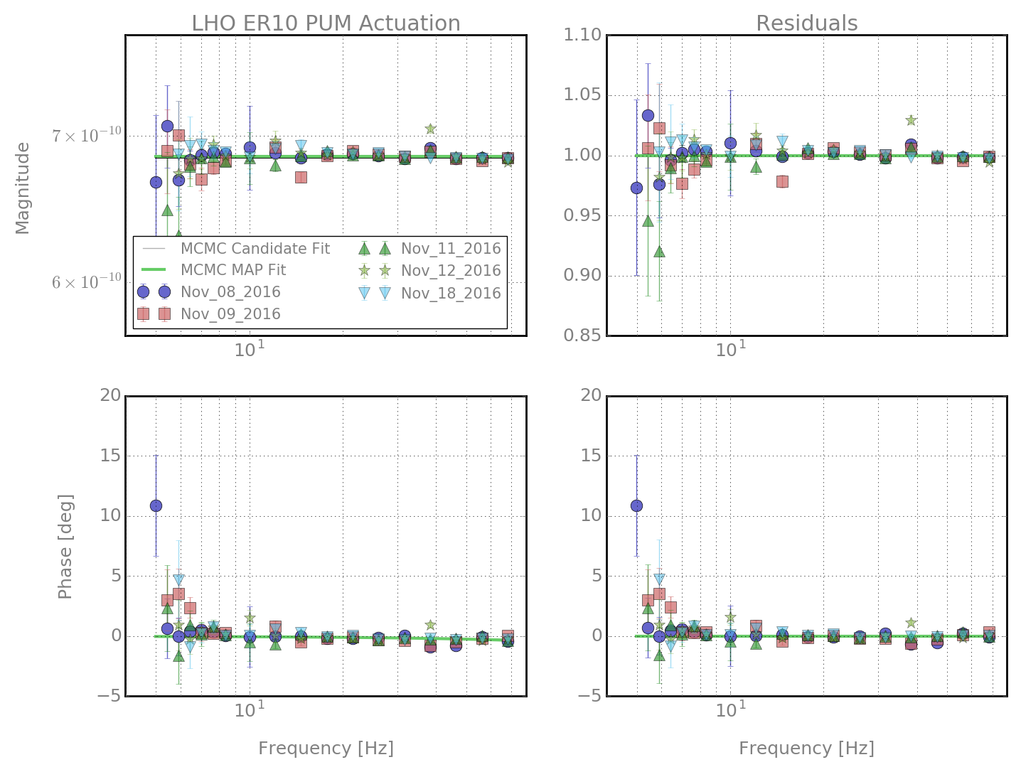
(1) Gathering all the Newtons/count actuation function measurements for the three stages (UIM, PUM, TST) from November 8th, 9th, 11th, 12th, and 18th.
(2) Running an MCMC over the physical parameters gain and delay for all three stages. (Only used freq < 10 Hz for UIM, freq < 100 Hz for PUM)
(3) Plot MCMC cornerplots and resulting residuals uncertainty budget from the MCMC PDFs.
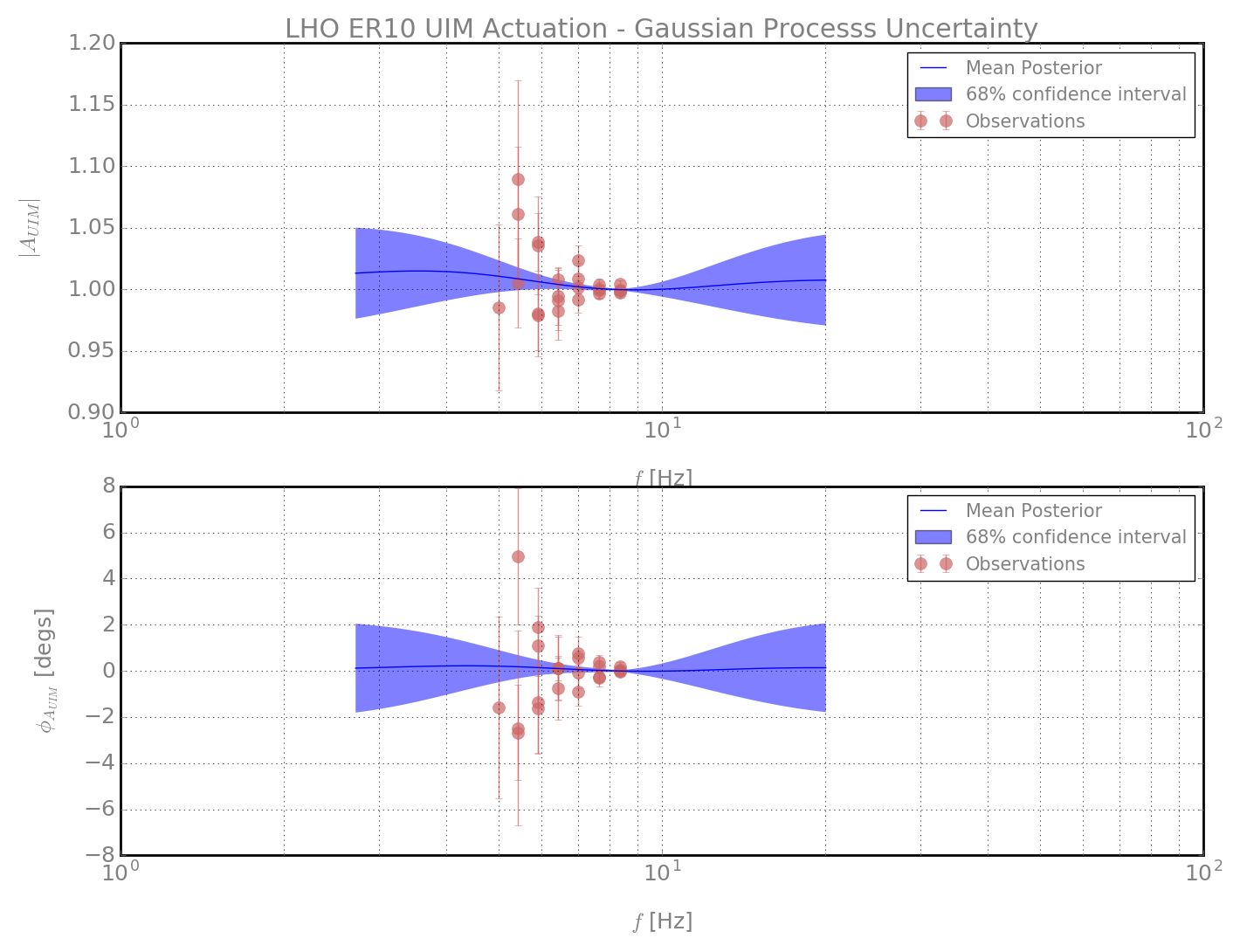
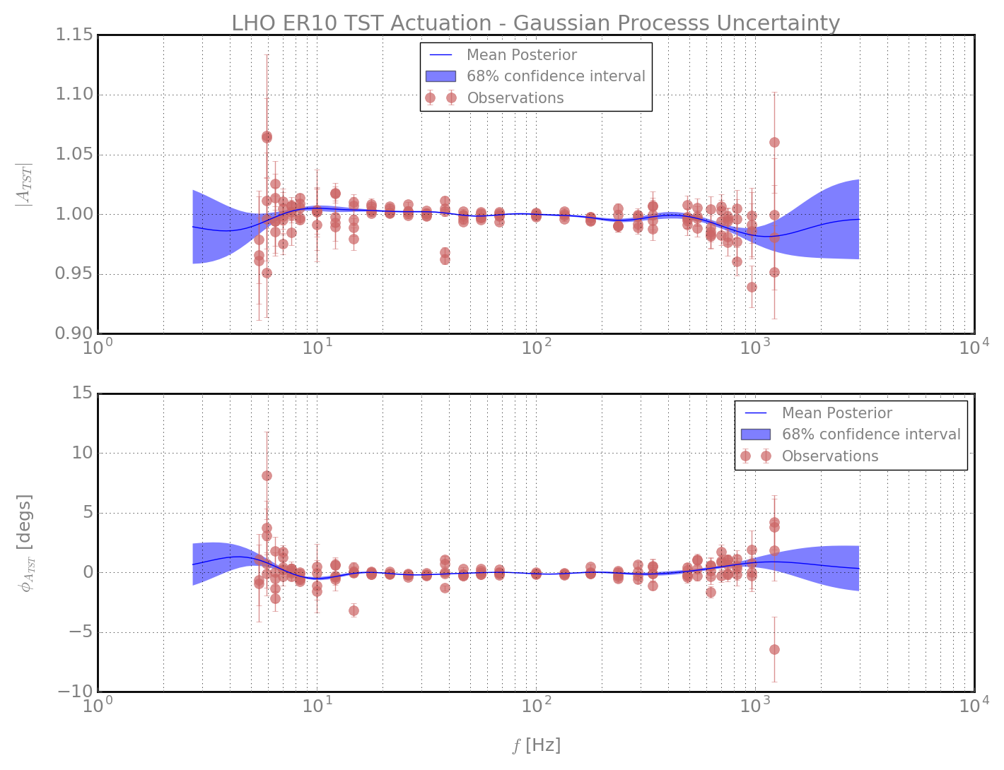
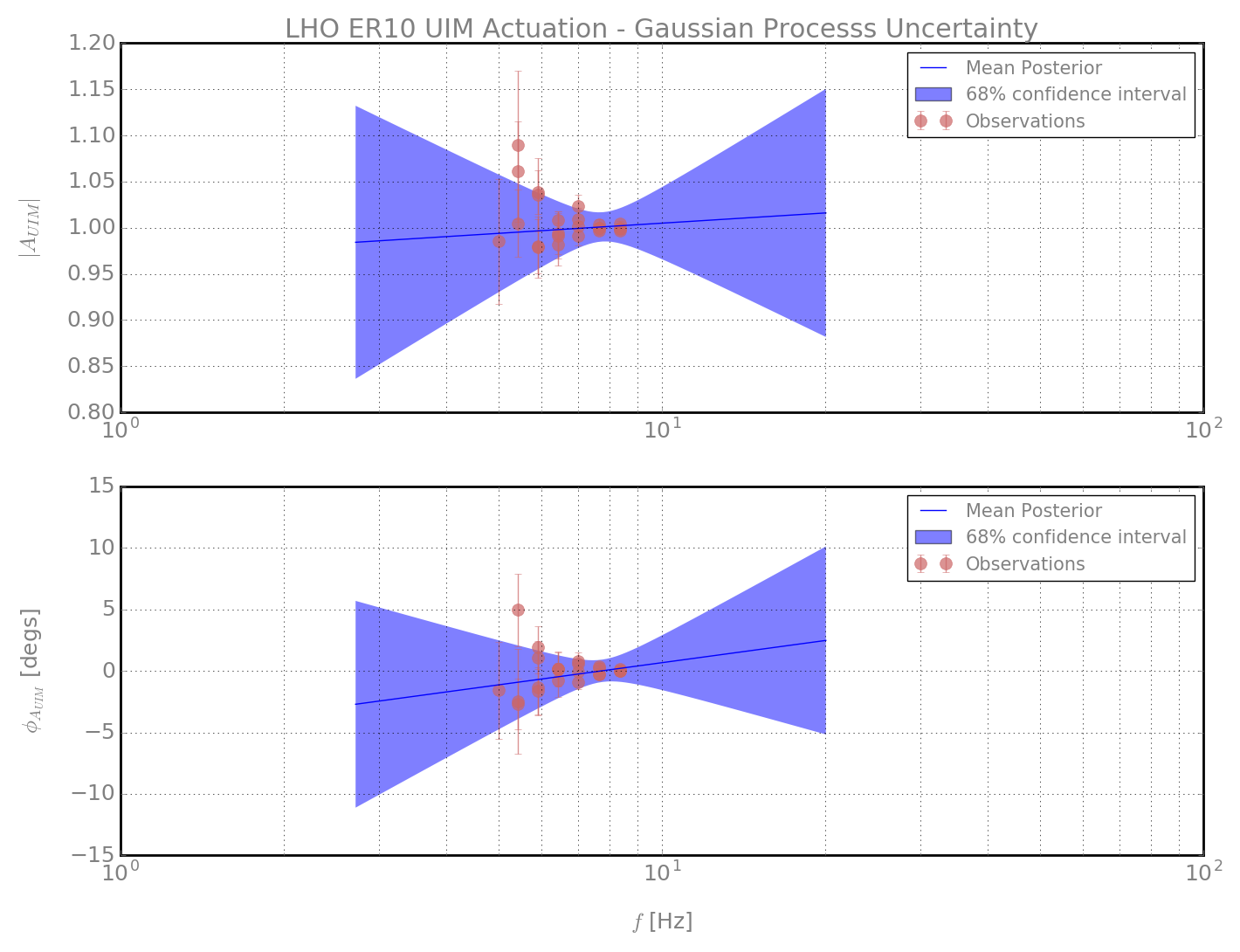
(4) Take the residuals from the MCMC physical parameters' fit, and plug them into a Gaussian Process with kernel k(x,y) = a + b * exp(-0.5*(x-y)**2/l**2), where a, b, and l are the hyperparameters of the GP.
(5) Train the GP on the residuals, and produce a mean posterior fit and an uncertainty budget from the trained kernel.
TL:DR : Take measurements -> Physical MCMC -> Unmodeled GP -> Frequency-Dependent Systematic Error +- Uncertainty Budget
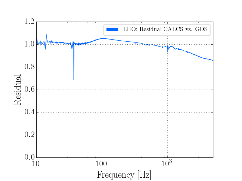
The mean posterior fit is the frequency-dependent systematic error. The uncertainty budget is also frequency-dependent.
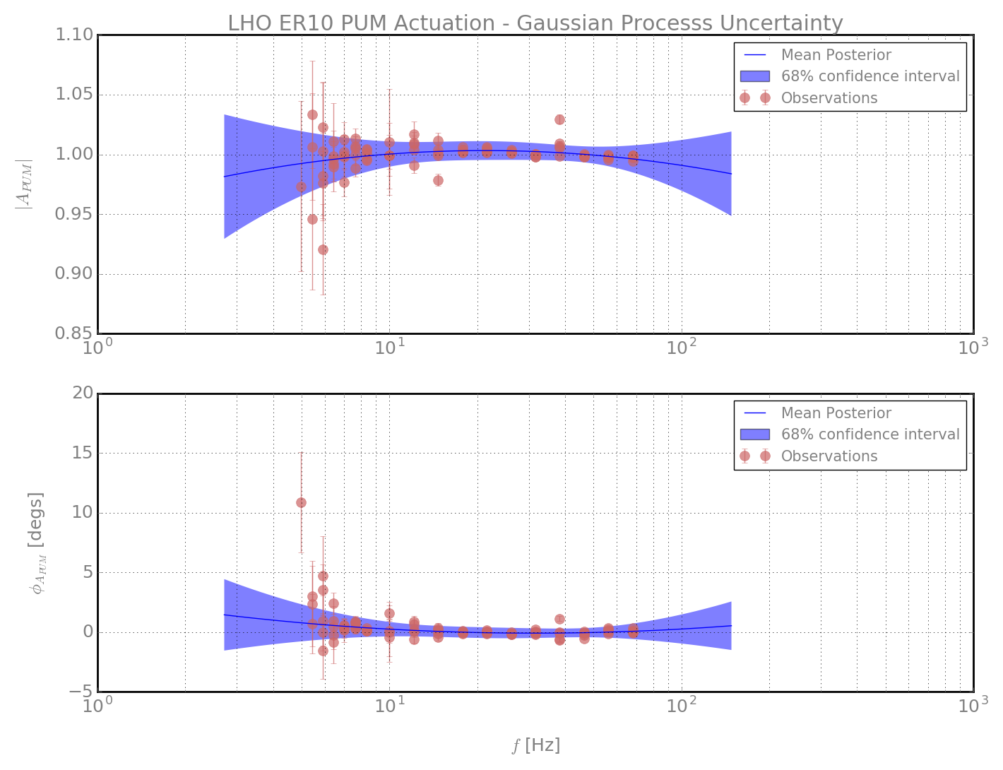
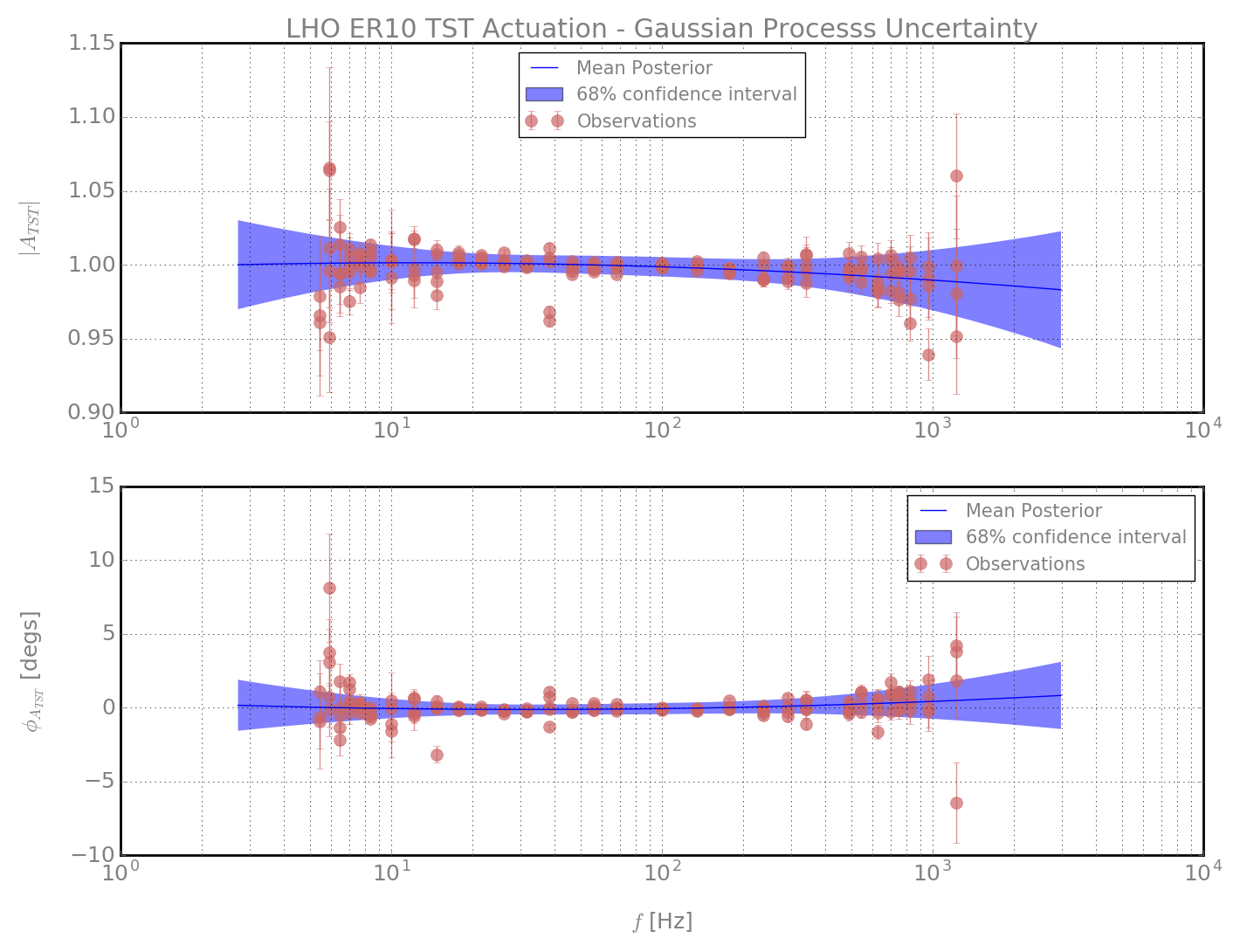
The Gaussian Process results are shown in Plots 1, 2, and 3 for the UIM, PUM, and TST stages. The 1-sigma, 68% confidence intervals are plotted.
I want to call attention to how small the uncertainty is in the bucket.
The frequency-dependent uncertainty in the bucket is on the order of 0.1%
This is exciting, but is it real?
Points in favor:
(1) We have five sets of measurements, and uncertainty roughly goes as 1/sqrt(N) where N = measurement number. This allows us to win a lot where the measurements are nearly the same and the errorbars are small.
(2) The GP fit hits most of the measurement errorbars.
(3) Uncertainty expands where we have less information.
Points against:
(1) Overfitting might be a problem. There seem to be unphysical wiggles that nail our data in the bucket.
(2) This uncertainty budget is lower than ever before by a factor of 10. This requires extraordinary proof.
Rebuttals:
(1) We might be able to combat overfitting by lengthening the kernel length-scale and adding more noise to our measurements. Also, the whole point of this method is to capture unmodeled wiggles.
(2) The data analysis methods used are more advanced and designed to handle frequency-dependence.
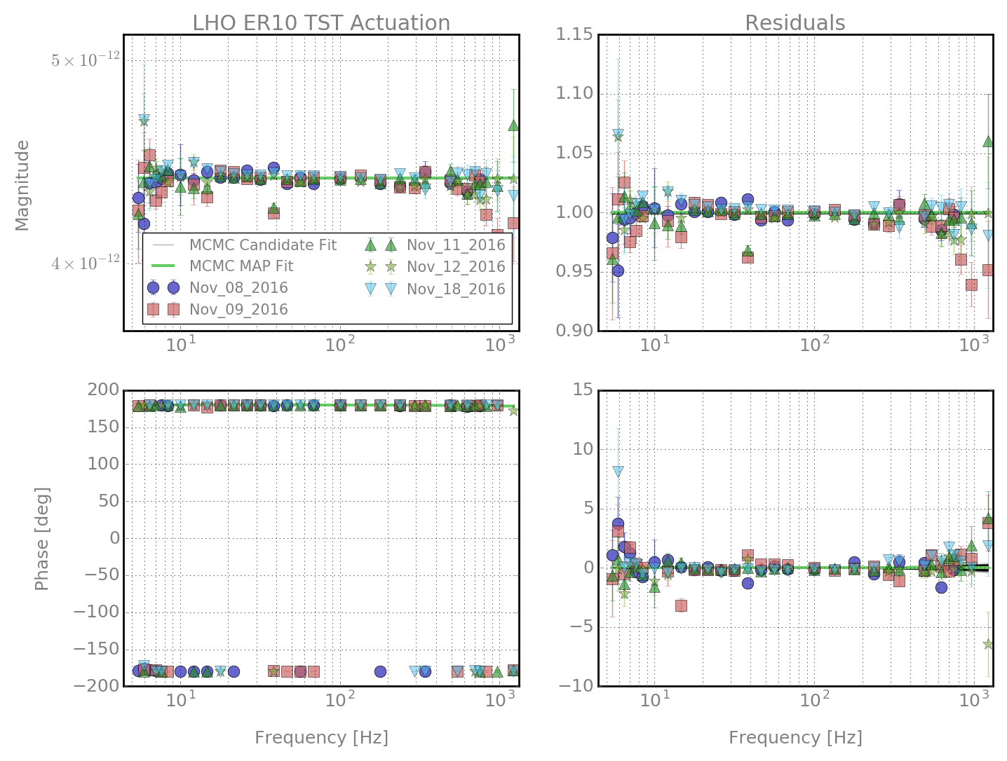
Plots 4, 5, and 6 are the UIM, PUM, and TST physical model MCMC fits with the measurements.
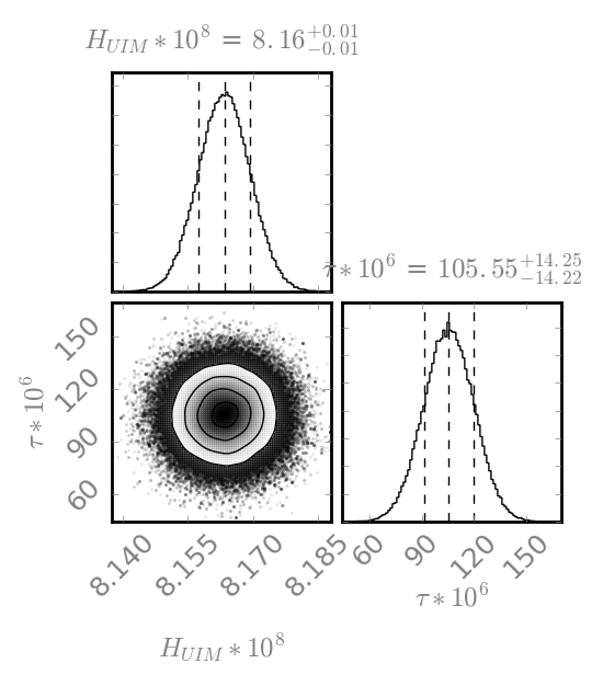
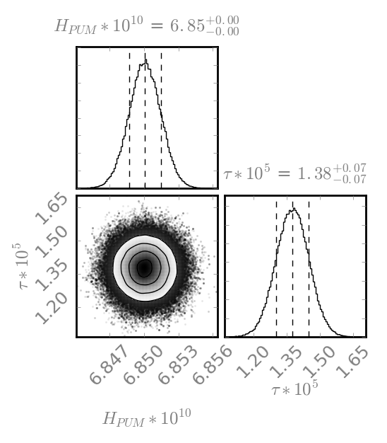
Plots 7, 8, and 9 are the UIM, PUM, and TST physical model MCMC parameter cornerplots.
A couple of points:
(1) The GP uncertainty doesn't take into account the uncertainty from the MCMC physical parameters. The GP uncertainty dominates nearly everywhere, since the MCMC uncertainty is so tiny (See plots 4, 5, 6). I may try to incorporate the MCMC uncertainty directly into the measurement errorbars that I input into the GP.
(2) A lot remains to be done. LLO actuation, sensing at both sites, and final response uncertainty.
(3) If these results hold, we may have uncertainty dominated by time-dependence. Stay tuned.