At 23:13 we received a "Gamma Ray Burst" Alarm.
Following L1500117:
-
Step 1: Checked to see if this is a TEST
-
What does this mean? Do Tests have the "INJ" flags? Are there any other types of flags for Tests?
-
On GraceDB, there was a little confusion. We could see a (1) GRB Report (EM_COINC) from Swift, but (2) around the same time, there were also some INJ EM_COINC's from CWB (!). The GRB's event time was over 2min after the EM_COINC's.
-
So was NOT a TEST
-
Step 2: Stand Down Time from 23:13 - 0:13utc
-
Step 3: Finally talked with LLO. They did not know about the GRB, so they went to go check. Heard them say they DID NOT receive audible alarm, but had "text notification".
THEN:
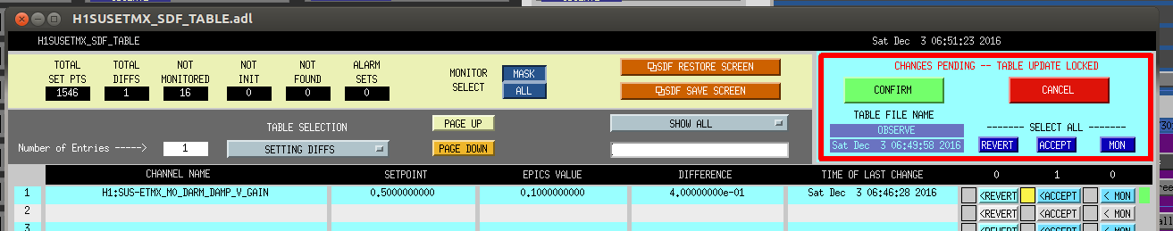
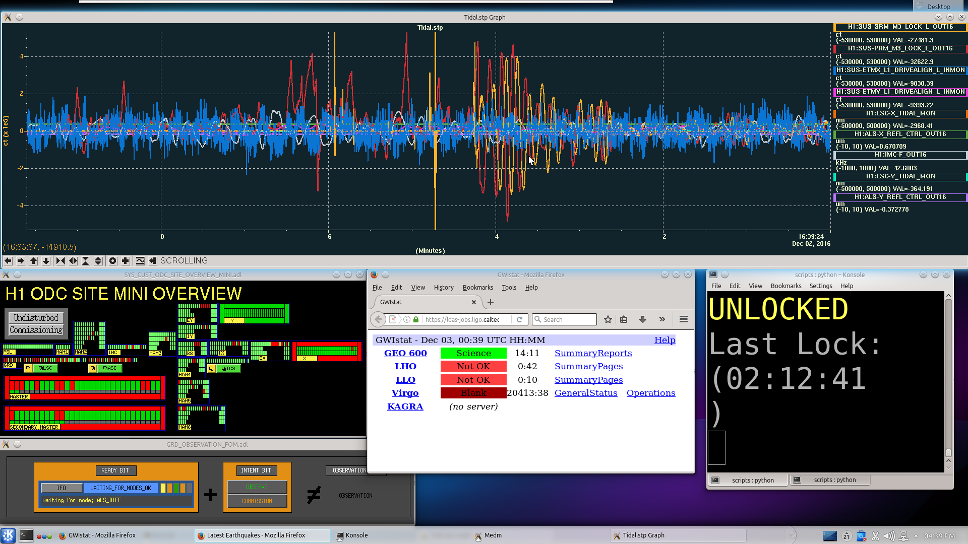
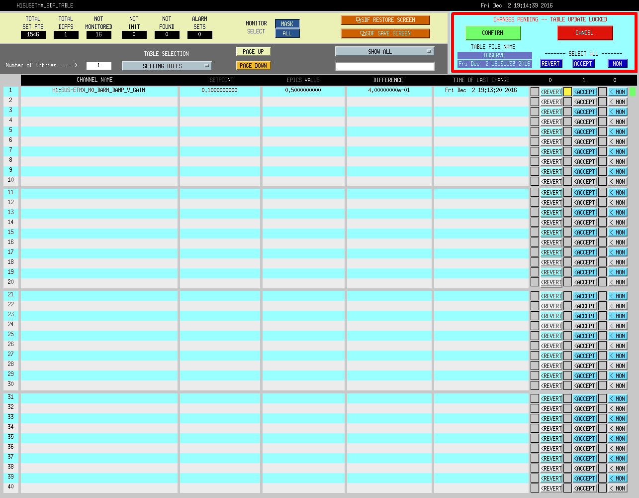
AT 23:21 We were bumped out of OBSERVING!! (Sheila noticed it, we didn't hear it for some reason during all the hub bub of figuring out the deluge of GraceDB reports.) It wasn't obvious why we were bumped out of OBSERVING. But since we tend to get bumped out due to SDF Diffs/changes, JimW looked at the DIAG_SDF node's log. On here he noticed we were getting DIFFS for the SDF NODE: sysecatx1plc2
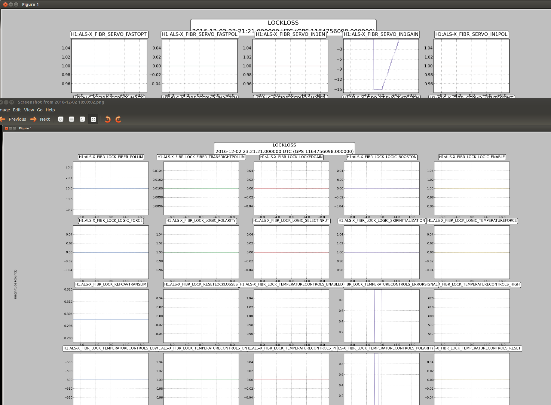
Unfortunately, when the diffs appeared they only happened for a few seconds (knocked us out of OBSERVING), and then go away. So it was hard to see what channels were in question. It happened several times, and managed to catch a glance at the channels in question. Words we saw in the channel were: ALS, Fiber, polarization. Since they deal with the ALS, we can probably safely say we can NOT_MONITOR these channels (but we should get a blessing from Keita). Or if we are in a fix in the middle of the night, and you are able to figure out who these elusive channels are, be sure to note the channels, NOT_MONITOR them for the night and then alog what you did.
Epilogue:
We ended up losing lock at 23:56--it's really noisy seismically with useism & wind.