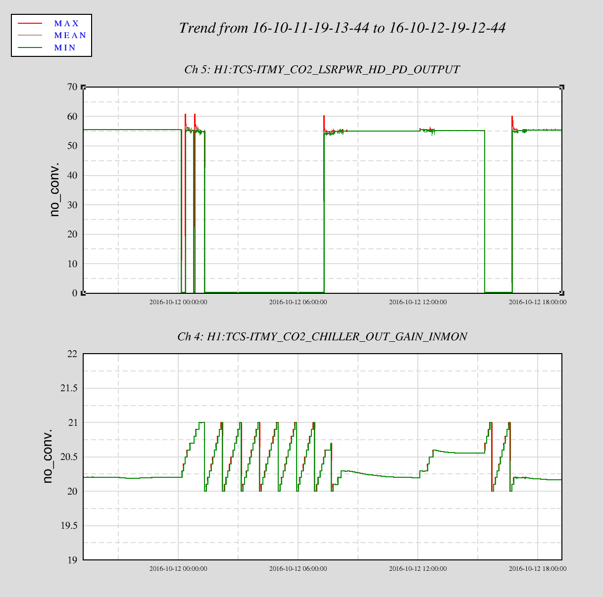
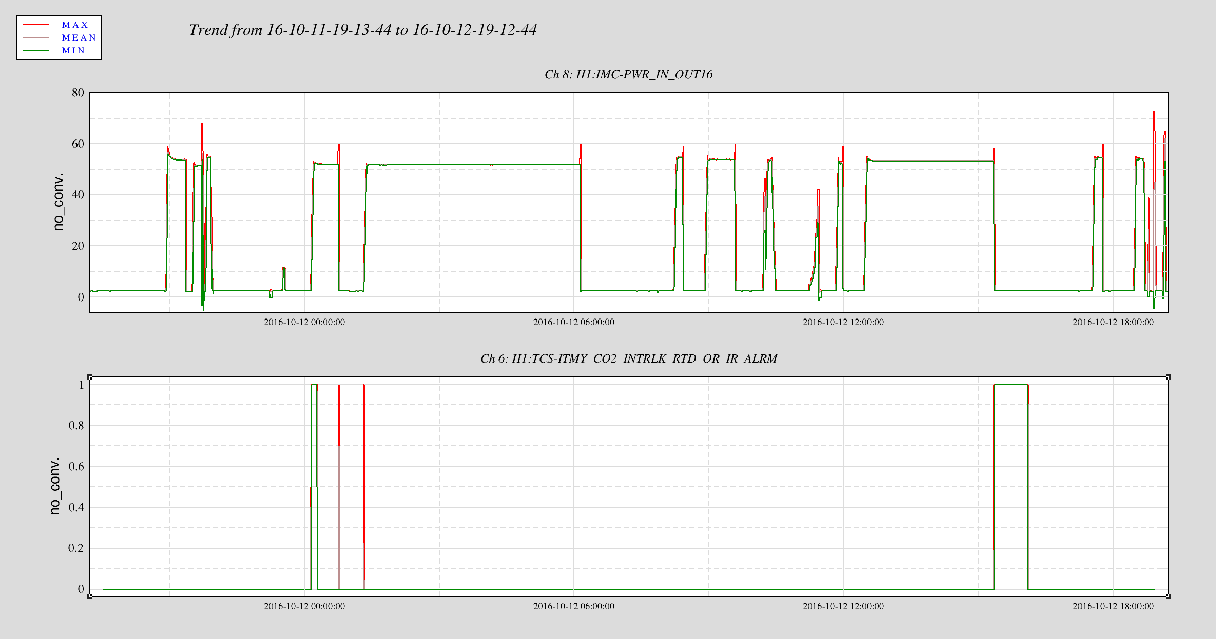
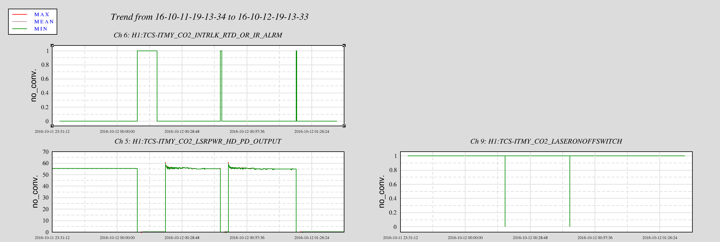
Title: 07/11/2016, Day Shift 15:00 – 23:00 (08:00 – 16:00) All times in UTC (PT) State of H1: IFO unlocked. Switched intent bit form observing to commissioning. Guardian error – "4 dead channels" & EPICs comm error Commissioning: Outgoing Operator: None Activity Log: All Times in UTC (PT) 15:00 (08:00) Start of shift. 15:00 (08:00) Guardian error 15:30 (08:30) Richard – Reset End-Y Beckhoff IOC 15:44 (08:44) Alfredo & Elizabeth – Going to the bridge over the X-Arm to put up a sign 16:25 (09:25) Sheila – Going into Optics Lab – Looking for BS optic 16:30 (09:30) Kyle – Going to Mid-Y to run test on rotating pumps 16:35 (09:35) Alfredo & Elizabeth – Back from X-Arm Bridge 16:53 (09:53) Sheila – Finished in Optics Lab – Going to Squeezer Bay 17:20 (10:20) Kyle – Back from Mid-Y 17:29 (10:29) Alfredo & Elizabeth – Going to the bridge over the X-Arm to work on new sign 17:44 (10:44) Alfredo & Elizabeth – Back from X-Arm 18:06 (11:06) Sheila & Haocun – Going to ISC table at HAM2 – They will open the table. 19:28 (12:28) Sheila & Haocun – Out of the LVEA. 19:46 (12:46) Kiwamu & Nutsinee – Transitioning LVEA to Laser Hazard 20:51 (13:51) Kiwamu – Going into LVEA to adjust ITM-X and ITM-Y IR cameras 21:13 (14:13) Dick – Going into LVEA to Squeezer bay to look for parts 21:21 (14:12) Kiwamu – Back into LVEA to work on camera alignment 21:27 (14:27) Richard – Bring a tour through control room 21:32 (14:32) Dick – Out of the LVEA 21:42 (14:42) Kiwamu – Out of LVEA 23:00 (16:00) Turn over to Ed End of Shift Summary: Title: 07/11/2016, Day Shift 15:00 – 23:00 (08:00 – 16:00) All times in UTC (PT) Support: Jenne, Sheila, Kiwamu, Stefan, Incoming Operator: Ed Shift Detail Summary: End-Y Beckhoff IOC crashed. It has been restarted. 16:40 (09:40), IFO locked at INCREASE_POWER. IFO at 39.9W, Stefan is taking data.17:10 (10:10) 19:46 (12:46) LVEA transitioned to Laser Hazard. Will leave it Laser Hazard until Peter is finished with the hardware hunt tomorrow morning. IFO has been up and down all day, while commissioners are working through various issues, adjustments, and improvements.
Sheila, Haocun
Due to the satuation of the photodetectors, we added a 90:10 beamsplitter (CVI BS1-1064-90-1025-45P) in the POP beam path.
WIth the input power of 2W (1.97W) in the interferometer:
Power before adding the BS: POPX: 5.74mW POP Air A: 2.56mW POP Air B: 2.52mW (total: 10.82mW)
Power after adding the BS: POPX: 0.852mW POP Air A: 0.4mW POP Air B: 0.4mW (total: 1.652mW)
Power right before the BS: 10.88mW; Power right after the BS: 1.82mW.
PSL: SysStat: All Green, except VB program offline Frontend Output power: 34.4W Frontend Watch: Green HPO Watch: Green PMC: Locked: 0 days, 0 hours, 21 minutes Reflected power: 24.0W Transmitted power: 125.5W Total Power: 149.3W ISS: Diffracted power: 16.702% Last saturation event: 0 days, 0 hours, 21 minutes FSS: Locked: 0 days, 0 hours, 18 minutes Trans PD: 3.350V
The watchdog and its timers suggest the Stage2 Actuators went first but the traces (attached) show the T240 are what hit the trip limit. Has a bit of Earthquake shape to it. An M6.3 in Ecuador is a good candidate, with an origin time of 0211utc or 18mins before the ISI tripped. Oh yeah, there is that 3um/s excusion on the BLRMS Eq Band monitor...
No trouble reisolating the ISI this morning. An issue that popped up is that the Operators Overview showed no indication of the platform being tripped. It was obvious with the SDF being red with 60 differences. FRS 5852 filed.
I believe the missing red indicator is long standing dodgy logic on the OVERVIEW. It requires both stage 1 and 2 of the ISI to be in full trip for the ISI indicator to turn red. This should be changed if the operators depend on this in any way to indicate to them that the platforms are in good shape; as is, it is not sufficient for that. This is not related to the BSC ISI Model Upgrade from a few weeks ago.
The smoothing of the CP level is done on the milliamps read in from the ADC before it is converted to a percentage full. Currently the smoothing parameter is set to 0.999 on each of the CPs. I have attached full data trends over an hour of the level of each CP read in milliamps before and after being smoothed. They all appear reasonable. The code for the smoothing filter and a dataviewer template with the channels used for the trends is also attached.
0930 - 1010 hrs. local -> To and from Y-mid Opened exhaust check-valve bypass-valve, opened LLCV bypass valve 1/2 turn -> LN2 at exhaust in 50 seconds -> Restored valves to as found configuration. Next CP3 overfill to be Wednesday, July 13th. Also, 0945 - 1000 hrs. local -> Ran purge-air supply and QDP80 at Y-mid (maintenance task)
Jeff B. Noted white screens on EY beckhoff channels. We logged into the computer could not find any obvious errors besides the IOC being down. The Beckhoff system was still running but the IOC that interfaces to EPICS had crashed. It was restarted and connections came back.
All subsystems reported no significant problems or issues. ER9 run has finished. Vern thanked all who put in so much time and effort to make this run a success. Problems brought to light during ER9 are being addressed. The Tuesday Maintenance window will be given over to a site wide effort to locate missing equipment. At this time, no other maintenance items are planned.
I wanted to look at the digital camera integrated intensities of all PRM optics during the power increase, in an attempt to find lost power.
First step: find a camera exposure setting that does not saturate at 40W:
H1:VID-CAM13_EXP 3000 (PRM)
H1:VID-CAM08_EXP 1000 (PR2)
H1:VID-CAM14_EXP 1000 (PR3)
I already recorded the corresponding sum signals during the first attempt (UTC Jul 10 23:50 - Jul 11 00:30), but had to adjust the exposure settings along the ways. The interesting sum signals are:
H1:VID-CAM13_SUM
H1:VID-CAM08_SUM
H1:VID-CAM14_SUM
Once at 40W, I noticed that PR3 shows quite a bit off overspilling light below PR3 (and some above, but not on the side). By moving the H1:ASC-POP_A_PIT_OFFSET from the nominal 0.36 to 0.55, I was indeed able to reduce the total light seen by the PR3 baffle camera by 32%. At the same time the recycling gain and arm transmitted power went up, but only by 2% (PR GAIN from 28.4 to 29.0 / TR_X_NORM from 1080 to 1102). There is more going on than this...
=============================
Along the way I kept loosing the FSS lock. Not sure what changed this week, so I won't debug this one.
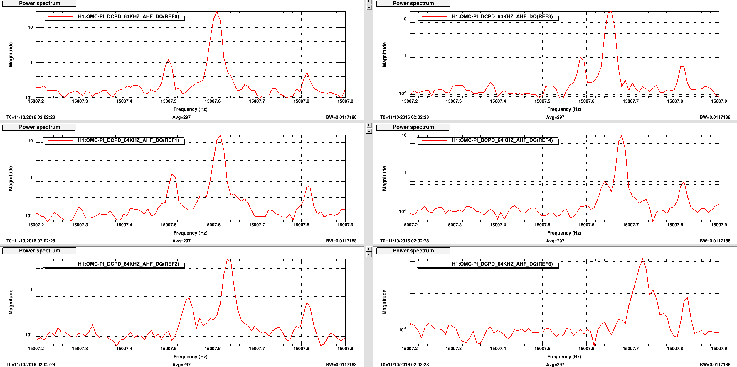
Intent bit set at 05:30 UTC. PI modes are not well damped but they're controlled for now. There are few weird things I noticed about some of the PI modes:
As I was writing this alog, the ifo went DOWN because of ETM bounce mode (not sure which ETM, possibly both). I didn't put them on my StripTool since I was assume only ITMX has problem. Huge mistake...
Locked again at NLN. Intent bit switched to Undisturbed at 07:22 UTC. I'm going to stick around a bit to keep an eye for the bounce mode and PI. PI modes are somewhat under control. Bounce and Roll modes seem pretty well damped at this point.
Hence a beautful ending of ER9.
ITMX bounce mode was ringing up so I flipped the sign of the gain. Unfortunately I accidentally flipped the wrong gain (instead of ITMX Bounce I flipped ITMX Roll). Likely caused ITMY Roll to ring up and blew the lock.
Lockloss again due to ETMY PI 15009 Hz rung up.
This time I tried to catch the mode early before power up. I was able to damp it just fine using -60deg -10 gain. However, the mode jumped when the IFO entered COIL_DRIVER (at about -22 mins) and never ring down. I thought I was able to damp it with opposite gain (-12 min) but it rung up shortly after.
3:07 UTC Lockloss at COIL_DRIVER
PR gain and SRC seems unstable. I called Jenne and this seems to be a problem of SRM not following the rest of the SRC (that I didn't know I should be moving). Guardian didn't seems to know that it has lost lock and wouldn't move to DOWN. This happened twice now. I had to requst DOWN manually. This is already a known problem. Nevermind.
There was another lockloss at INCREASE_POWER (02:14 UTC) that I didn't alog. Now that I lost lock around the same place it's becoming a pattern so I thought I would mentioned.
J. Warner, R. Schofield, (J. Kissel remotely) Jim called me this morning around 10a PT informing me that the ETMX ESD was unresponsive, preventing any lock re-acquisition. We eventually found that one leg of the HV power supply to the HV ESD driver at EX was off; unknown as to why. I reminded Jim how to restart it, then the ESD driver came back to live as normal after hitting the ON/OFF button on the HV ESD driver itself (no need to disconnect/reconnect any cables this time). Diagnosis timeline: I logged in an found that the HV monitor channels were all zeroes in the bottom right corner of the SUS ETMX overview, even though the digital request was the usual large bias and linearization voltages on the signal quadrants. I also noticed that because these monitor channels were reading zeros, the ISC_LOCK guardian -- which was in the DOWN state -- was hammering the remote ON/OFF button (I thought we fixed this??). After requesting that the ISC_LOCK just CHILL (i.e. pausing the guardian node), I waited a bit to let the HV ESD driver's internal mirco-processor relax then tried to remotely restarted it again. No dice. I advised Jim to head down to EX so we could debug together there (he'd gone with Robert). He went immediately to the VEA to try the ol' plug-un-plug cable trick, and found that the physical ON/OFF button did nothing, and that some indicator lights had shown that a leg of the 430 V input was red / dark. So, "we" went out to the entry foyer where the two HV power supplies live, and he found one off. We turned it back on -- - Flip the rocker switch up to ON (wait for boot cycle to complete) - On the keypad, type - VSET > 430 ([V] for the amount of output voltage) > Enter - ISET > 80 ([mA] for the internal current limit) > Enter - Output ON/OFF and then Jim went back out of the floor, the ESD HV driver looked much more lively, so he hit the button and the box came to live and I saw the voltage monitor channels go to their usual values. The only thing I can think of that trips the HV power supplies for the ESDs is the vacuum system (and when it does, it usually trips both), so I did a cursory vacuum system check on the EX overview screen, and didn't see anything crazy (i.e. I saw a bunch of green lights, and both vacuum Pirani gauges were sitting happily at ~1e-9 Torr. We'll debug more on Monday when I don't have to use the fragile remote connection to CDS.
The Vacuum interlock is tied to both power supplies with the same relay so this is probably not the cause. These supplies have very sensitive protection circuits and we are not really using the supplies for what they were designed for so it was probably a single supply protection circuit trip do to some loading transient.
Around 5:45 UTC, DARM started to glitch about every two seconds. The period is not exactly 2 seconds (I think it's just a little bit longer) but it does look pretty regular. I checked that the Pcal spectra look fine, so that's not the problem. Attached is the change in the DARM spectrum. I wanted to use GDS-CALIB_STRAIN, but I get something that looks like it has dynamic range issues. We need to look into why that's not working. In addition, I'm attaching a Omega scan of the glitches.
Andy, could you elobrate (probably with some examples) of what dynamic range issues you are having with GDS-CALIB_STRAIN? We have recently switched to double precision numbers to get rid of whitening/dewhitening and also there were a few filter changes. It would be nice to make sure that there are no problems on that side.
When I take a spectrum of GDS-CALIB_STRAIN, it looks like the first plot. This looks like an issue with spectral leakage from too much low frequency. The time series has a very large low-frequency component around 10^-12 (second plot). It used to be around 10^-18 (third plot), and not so much low frequency. I'm sure the plot could be fixed by detrending and using the right window, or at worst high passing, but it would be preferable not to have such a big low-frequency component, unless it's useful for something.
I'm still working my way throughout the ER9 run-averaged spectrum to compile a detailed line / comb list, but one artifact that jumps out at me is a strong 0.4853-Hz comb I haven't seen before, visible from its 19th harmonic at about 9.2 Hz to its 316th harmonic at about 153.4 Hz. This is likely related to the periodic glitches Andy found. There is also a new near-1-Hz comb (spacing = 0.9968 Hz), visible from its 21st harmonic at about 20.9 Hz to its 204th harmonic at about 203.3 Hz. This is a higher harmonic than I've seen before, despite having many fewer FScan SFTs to work with than in O1 (hence having a fuzzier noise floor to pick out harmonics from). Details and plots to come...
Summary:
As reported before (28236), ISS 2nd loop MEDM screen appears as if it sometimes doesn't agree with reality. Turns out that it never truly agreed with reality. For example, in the first attachment, both SERVO ON/OFF indicator and additional 20 dB gain indicator are red while these are ON.
I was bothered enough to investigate and found that the MEDM screen has numerous nonsense logic and that the guardians are not written MEDM-friendly. I made a quick dirty fix for MEDM as well as guardians.
What was wrong:
Before going into details, you need to know that ALL of PSL 2nd loop I/O that are binary in nature is done via 16 bit DAC (don't ask me why). The output of DAC is sent to optical coupler via a resistor (see e.g. D1300439). To make anything ON, you want some large positive voltage to drive the LED in the coupler. To make anything OFF, you want to send sufficiently small (e.g. zero-ish) voltage or negative voltage.
As you can easily guess, one of the problems is the lack of convention. People sometimes send +32000 and other times +32700 to make the same thing ON. Sometimes -32000 and other times 0 to turn it OFF.
On top of that, there are many bugs in MEDM screen such that color indicators check some nonsense bits that never change, value set on pressing button but changed to a different number on releasing the button, that kind of things.
What was done:
I changed most everything in MEDM as well as IMC_LOCK and lsclibrary such that:
It seems as if it's working for now.
Madness example:
Just as an example. Manually pressing CHANGE PDs button could have made you believe that you selected PD1-4 when PD5-8 (3rd loop) was selected in reality.
In the second attachment, you can see that the CHANGE PDs "1-4" button sent 32000 (40V-ish differential) when pressed, but then 1 (less than 1 mV) when released.
PD1-4 is selected with large positive voltage (or ON or HIGH or whatever), otherwise PD5-8 is selected.
When you manually pressed and released "1-4", the DAC output momentarilly went +40V differential, but immediately went down to some tiny voltage, so PD5-8 was selected in the end.
But the switch graphics was implemented assuming that non-zero output means PD1-4. Since the DAC output was 1 after pressing the "1-4" button, the graphics showed that PD1-4 was connected instead of 5-8. The PD indicator color box didn't help either as it checked the bit 2 of the DAC output, and it only turned to orange (CH5-8) only when DAC output was 32700.
The story was different for guardian as it used +32000 and -32000 for PD1-4 and PD5-8, respectively. When guardian did something, it looked as if PD1-4 was selected no matter what.
Addendum:
"The story was different for guardian as it used +32000 and -32000 for PD1-4 and PD5-8, respectively. When guardian did something, it looked as if PD1-4 was selected no matter what."
The above was incorrect, it turns out that the MEDM screen PD14/PD58 graphics happened to agree with reality when the guardian was doing it.
ISC_LOCK lets IMC_LOCK handle most of the 2nd loop board switching except for closing the third loop (i.e. selecting PD5-8) when ISC_LOCK bypasses IMC_LOCK and uses lockISS in ISC_library to send 0 to DAC. MEDM looked correct.
When selecting PD1-4, ISC_LOCK uses IMC_LOCK which sends +32000 to the DAC and again the graphics looked correct.