thomas.shaffer@LIGO.ORG - posted 00:01, Monday 28 November 2016 (31883)
Ops Eve Shift Summary
TITLE: 11/28 Eve Shift: 00:00-08:00 UTC (16:00-00:00 PST), all times posted in UTC
STATE of H1: Lock Acquisition
INCOMING OPERATOR: Cheryl
SHIFT SUMMARY: After the earthquake the useism and wind have picked up a bit, I just made it to Coil Drivers before losing it. Wind may be trending down so there is hope.
LOG:
- 00:24 Brief CP4 Major alarm. Lasted only about 30sec before it seemed to have fixed itself.
- 01:28 Robert to LVEA to start some injections.
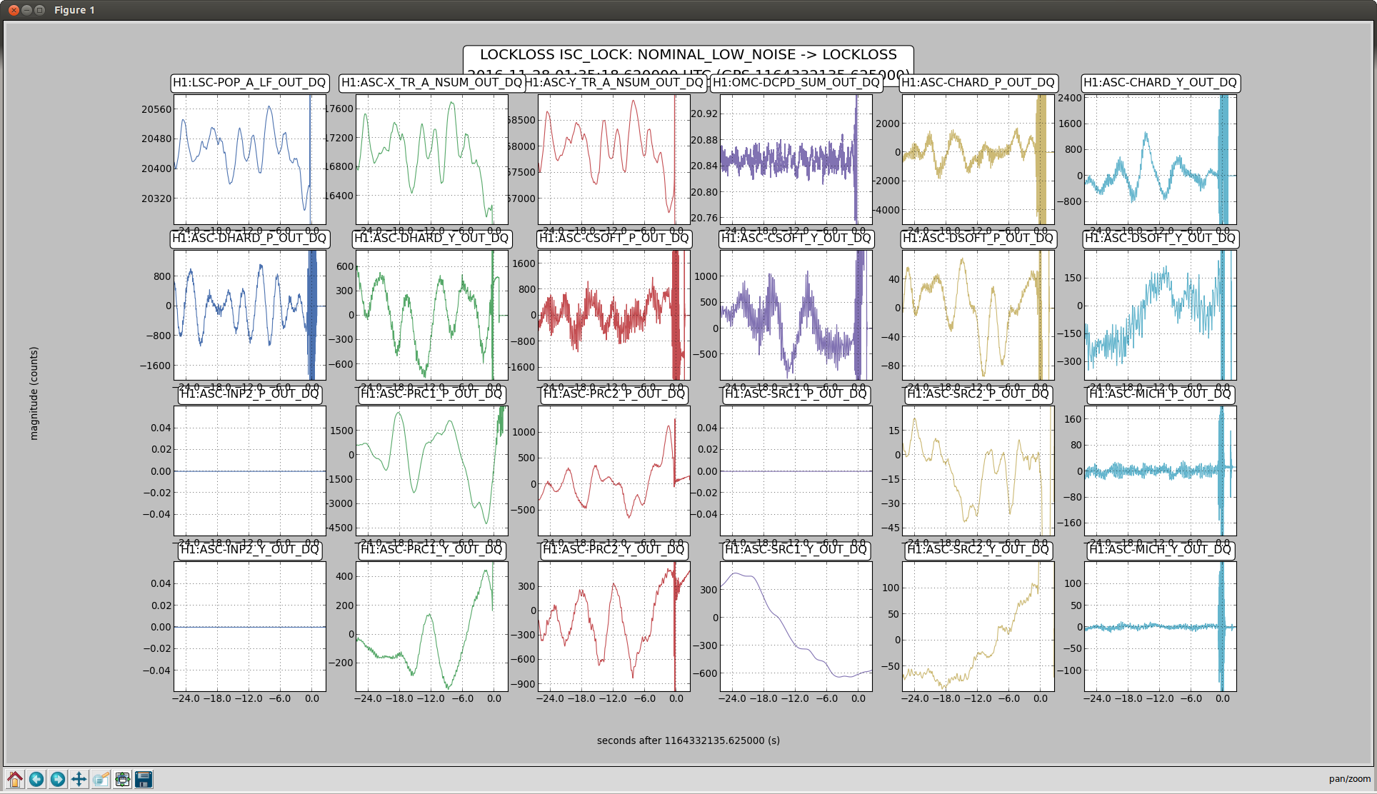
- 01:35 Lockloss. ~40mph gusts at the CS around that time. Robert said he could hear it in the LVEA. The attached shot looks like other times I have seen wind take us out so I'm going to say that was the cause.
- 02:26 NLN, took a few tries but the wind seems a bit calmer now. About to run a2l.
- 02:42 Robert back into the LVEA
- 04:38 Lockloss. Earthquake that isn't on USGS yet. (4.8 Off the coast of Oregon)
- 07:26 Brief CP4 alarm again.
Images attached to this report