Following up on the DetChar report of ETMx oplev laser glitching causing problems, I confirmed (using the DetChar summary pages) that the laser was indeed showing signs of glitching. I also noticed the ETMy laser was also showing signs of glitching. I increased the power for both lasers to hopefully get them into a thermal state they are happy with. I used the Current Monitor (outputs a voltage to monitor the current delivered to the laser diode) port on the back of each laser as a guide. The changes were:
-
ETMx
- Current Monitor Before: 0.814 V
- Current Monitor After: 0.830 V
-
ETMy
- Current Monitor Before: 0.861 V
- Current Monitor After: 0.880 V
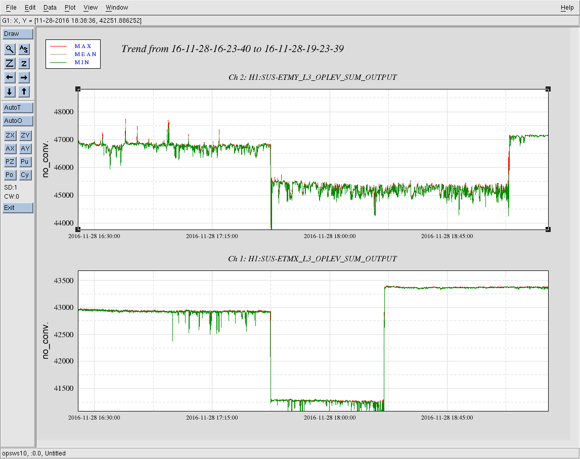
Seeing as I had to open the cooler for both lasers they will both need 4-6 hours to return to thermal equilibrium. At that point a determination can be made as to whether or not this helped at all. The attached 3 hour trend of the oplev SUM for both optical levers gives hope; after the power increase the SUM signal is quieter for both oplevs. I will leave WP 6348 open for now as more adjustment may be necessary to fix the glitching.
Further power adjustment for both lasers this morning as both were still showing signs of glitching (better than yesterday morning, but not gone). Changes are:
-
ETMx
- Current Monitor Before: 0.830 V
- Current Monitor After: 0.845 V
-
ETMy
- Current Monitor Before: 0.880 V
- Current Monitor After: 0.897 V
As before these lasers will need ~4 hours to return to thermal equillibrium before I can assess whether or not this latest tweak helped.