Jeff K, Kiwamu I, Darkhan T,
Overview
The CAL-CS EPICS records for tracking temporal variations of the DARM parameters have been updated at 2016-11-21 22:03:46 UTC. These values are identical to the ones in LHO alog 31677 from yesterday, i.e. D20161120_H1_CAL_EPICS_VALUES.m and D20161121_H1_CAL_EPICS_VALUES.m are identical.
New values have been accepted in SDF_OVERVIEW.
Details
Following DARM paramemter files were used to calculate these values:
${CalSVN}/Runs/ER10/Common/params/IFOindepParams.conf              r3752

	${CalSVN}/Runs/ER10/H1/params/H1params.conf                        r3826

	${CalSVN}/Runs/ER10/H1/params/2016-11-12/H1params_2016-11-12.conf  r3786
And the DARM model scripts from
${CalSVN}/Runs/O2/DARMmodel/* r3814
The *.m file with EP1-9 values and the verbose output are attached to this report. All of the files have been committed to CalSVN at
ER10/H1/Scripts/CAL_EPICS/
D20161121_H1_CAL_EPICS_VALUES.m

	20161121_H1_CAL_EPICS_VALUES.txt

	20161121_H1_CAL_EPICS_verbose.log


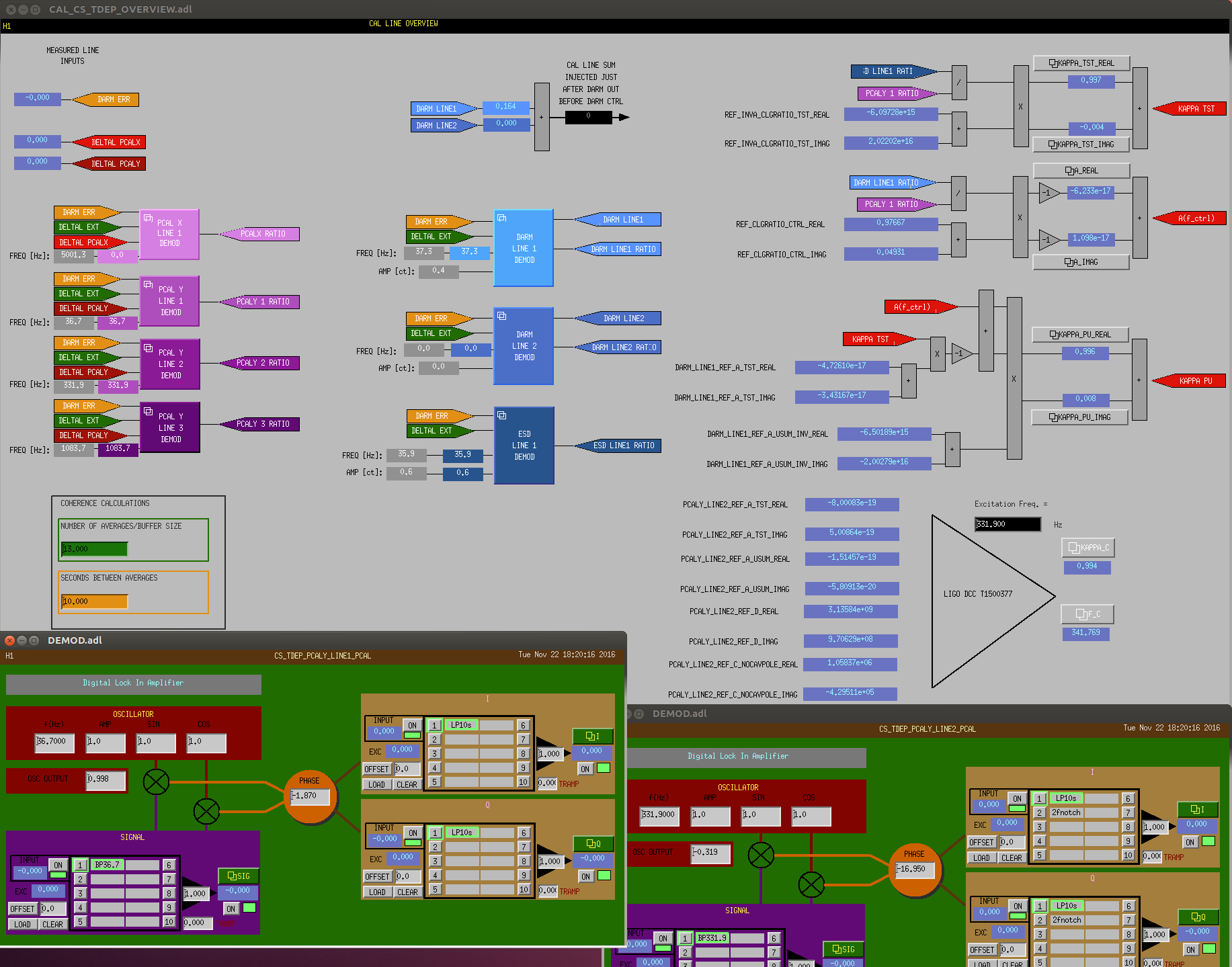
Just a minor note---the QPD one looks at is the AS_C QPD. (i.e. Anti-Symmetric port "C" QPD & not the ASC QPD).