More is said than is known and more is known than is true -- More likely added by other but may be of interest to all who use SDF
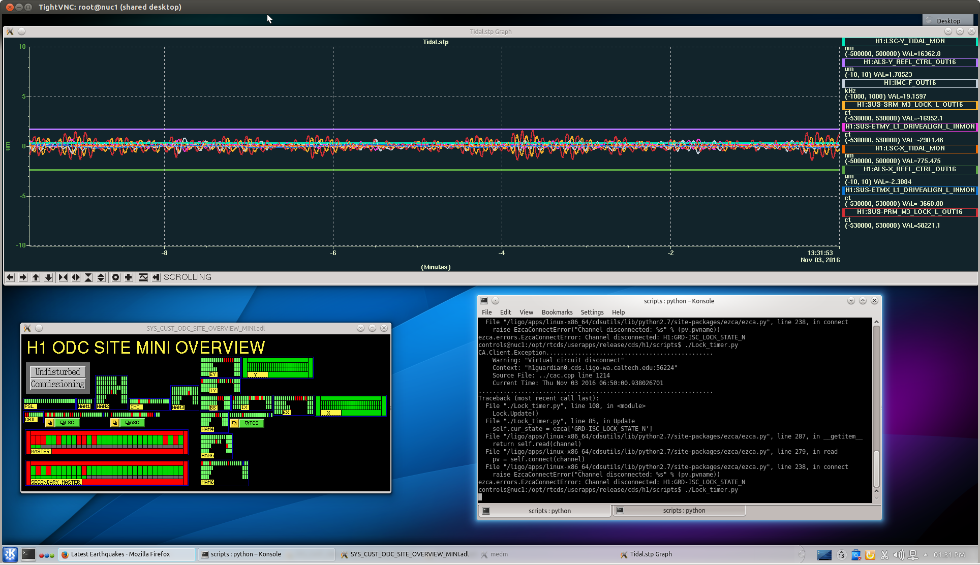
Not understanding what SDF was doing in certain situation led me to test a few things and report.
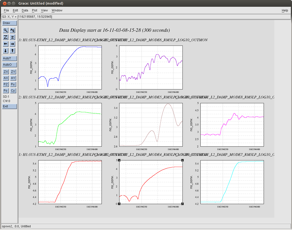
I looked in the HAM2 HEPI files as an example. In the Front End Target area all files were owned by controls and writable by owner and group. There were h1hpiham2_burt_date_time.snaps created by the FrontEnd when it cleanly shuts down. There are also safe and OBSERVE date_time.snaps and the safe and OBSERVE.snap files that are sybolic links to the USERAPPS area.
In the USERAPPS/hpi/h1/burtfiles area there are all the h1hpi{chamber}_safe & OBSERVE.snap files. The safe files are owned by controls and the OBSERVE files are owned by hugh.radkins; all files are writable by owner and group.
TESTS:
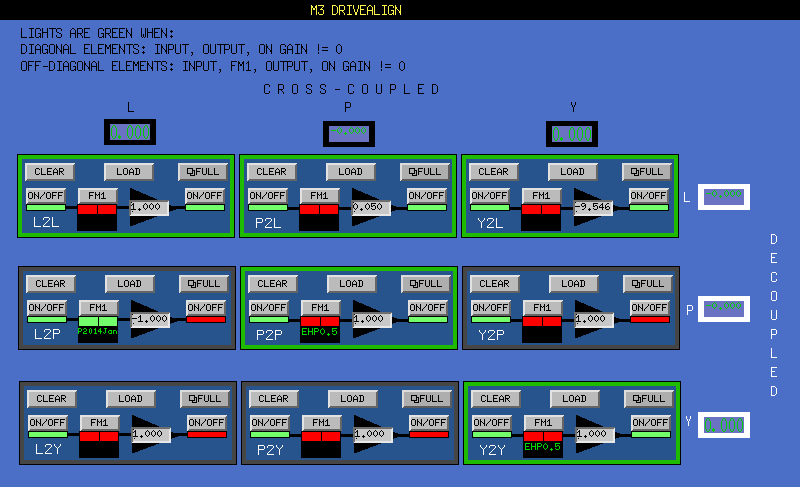
On the SDF TABLE medm, made a change(diff) and accepted and confirmed on that medm. The file was updated in USERAPPS, AND, a dated snap owned by controls was created in the target area--not expected.
On the SDF_SAVE medm, selecting OVERWRITE and clicking SAVE FILE does the same thing--It does overwrite the USERAPPS snap file but it also unexpectedly creates a new dated snap in the target area.
On the SDF_SAVE medm, selecting TIME NOW and clicking SAVE FILE does what one would expect; it creates a new dated snap in the target area and does NOT update the USERAPPS snap file.
Now, I change the write permission on the {chamber}_OBSERVE.snap file in the USERAPPS area to OWNER (hugh) only. Restart medm as controls. When I accept and confirm a diff, it creates a new dated snap in the target area but fails to update the snap file in the USERAPPS area. No notification of this was seen on the computer.
So if someone, logged in as themselves, attempts to accept and confirm changes with SDF, they will fail to update the USERAPPS snap file if:
*) they are not the owner and the file permissions are not group writable, or
*) they use the SDF_SAVE screen (rare for most commissioners maybe?) and do not change the FILE OPTIONS SELECTION to OVERWRITE.
Okay--gotta meeting, forgive the errors and omissions.
