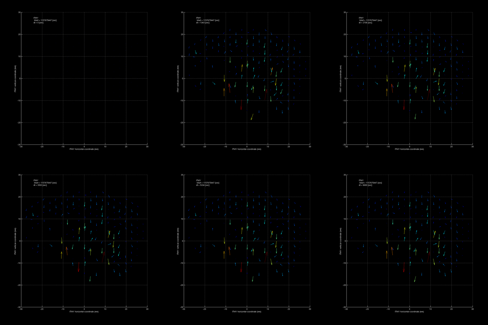
Carlos, Dave, Aidan:
h1tcsey was upgraded from U10 to U14. This week Aidan and I were able to install all the packages needed for HWS operation. We have handed the system over to Aidan and the TCS group for commissioning of this system.
Install instructions are in the wiki:
https://lhocds.ligo-wa.caltech.edu/wiki/HWSServerInstall
A busy maintenance day.
ISI-HPI EY BRS model change WP5798
Hugh, Jeff:
The h1isietmy and h1hpietmy models were changed to use the newly installed BRS in EY, same as what was done at EX.
SEI End Station SUSPOINT and GND-STS transmission to OAF WP5799
Hugh, Jeff, Joe B, Dave:
The suspoint and gound STS channels were transmitted from the end station ISI models to the corner OAF model using an additional RFM channel per arm. The two channels were MUXed into a single RFM channel. The path is: both channels sent from h1isietm[x,y] to h1peme[x,y] via two Dolphin channels. The two channels are filtered and then mux'ed inside h1peme[x,y] and sent out via a single RFM channel. The OAF model demux'es the RFM into two channels, assuming a single cycle delay in getting the data.
SEI HAM SUSPOINT addition WP5796
Hugh, Jeff:
The suspoint code was added to all the HAM ISI models.
SUSAUX upgrades WP5804
Jeff, Betsy:
Latest susaux model changes made.
Guardian PSL node added WP5797
Jamie, TJ:
new node added. Still needs to be added to DAQ?
NAT router OS upgrade WP5800
Ryan, Carlos:
Upgraded lhocds nat router to latest version. Discovered some issues, old system was reverted. Will invesitgate offline.
Machine reboots for security patching
Carlos:
machines which required rebooting for OS patching were rebooted.
DAQ frame writer instability, move wiper from writer to solaris server
Dave, Jim:
On monday we moved the h1fw1 wiper from h1fw1 to h1ldasgw1, running hourly at 10 minutes in the hour. Tuesday we did the same for h1fw0, running on the hour.
Accidental restarts
cast of many:
We had two accidental restarts.
Around 9am the timing slave on h1lsc0 IO Chassis was powered down. Initially we restarted all the models, but later in the day Evan reported bad ADC channels, we we then did a full computer+IOChassis power cycle in the afternoon.
Around 4pm the h1psl0 IO Chassis was accidentally glitched. We did a full computer+IOChassis power cycle to recover following our earlier LSC lesson learnt.
EX Beckhoff vacuum gauges moved from slow-controls to vac-controls
Richard, Dave, Patrick:
Patrick found the problem when we tried this last week, so this week the X4,5,6 BPG vacuum gauges were moved from their temporary slow-controls location to the final beckhoff VAC controls at EX.
The channel names were changed in the process. DAQ minute trends were changed to preserve old trend data (older archives still need moving).
DAQ Restart
Jim, Dave:
The DAQ was restarted several times over the day to support the above changes. We had two bad starts:
On one start all front ends resynced except for h1susaush56 which required a start_streamers, which fixed it.
On one start many frontends did not resync and required a start_streamers, during this h1psl0 went out of sync and many start_streamers did not fix it. We eventually did a second DAQ restart and all was good.
HAM 8: 8 mA @ IP and 3.8e-6 Torr at turbo HAM 9: 10 mA (no more red light) and 2.3e-6 Torr at turbo HAM 11: 10 mA+ (still with red light) and 4e-6 Torr at turbo (pressure went up)
This is a belated log. Some people suggested studying correlation between the cross correlated spectrum and DARM residual. So I looked into that.
I conclude that there is no clear correlation between the noise floor (or band limited rms) of the cross spectrum around 153 Hz and DARM residual.
[DARM residual and band limited rms]
Here is a plot showing how they evolved as a function of time throughout O1.
As seen in the plot, I do not see a clear correlation between the two data. Note that the band limited rms is the one for a frequency range of [150 156] and is artificially scaled and offsetted to make the plot more readable.
[DARM residual is a strong function of seismicity and ISI blend configurations]
Looking at the plot shown above, one can notice that there are some periods where the residual is small and steady, and the others are large by a factor of a few. This seems to be related to seismicity and the ISI blend configurations. Here I give one example study about it.
I looked into one particular interesting time where the EX ISI blend configuration was switched from one to another without losing lock. This is Dec. 26 2015 7:00-ish UTC (24483). The zoomed version of the above plot is shown below.
The lock stretch started at around 4:00 UTC of Dec 26 and the blend configuration was switched at around 7:00 UTC without losing lock. When the EX ISI blend was switched, the DARM residual increased by a factor of two or so. This is simply because of an increase of the low frequency motion. I made two spectra of the DARM residual, one for the time before the blend was switched and the other for the time right after the blend was switched.
From the plot, it is clear that the low frequency motion below 0.4 Hz increased after the switch while the rest of the frequency contents remained unchanged. So this tells us that the fluctuation of DARM residual is a strong function of seismicity and ISI blend configurations. Although I have not looked into other days throughly, I am guessing that the fluctuation we see in the DARM residual is just a measure of a combination of seismicity and ISIs' blend configurations. We know that the blend configurations were switched many times during O1 in order to stably lock the interferometer against winds and micro seismic.
Jenne, Hang, Sheila, Keita, Evan
Tonight it seems like we made some progress, although we haven't powered up yet.
The first screenshot attached shows the symptom of the xarm soft loop not working, as we power up the optical levers move, and the loops work to bring the QPDs back to their starting points but bring the optical levers in the wrong direction, causing the green to become misalined. The second screenshot shows the individual segments of the X arm QPDs durring this time. The third screenshot shows a power up (to 20 Watts) towards the end of O1, with no evidence of saturation, despite almost twice the power on each segment. The last screenshot shows the noise of each segment, the bottom panel is before reducing the whitening gain, the top panel is after (the A2L dither lines were on, that is the forest of lines around 20 Hz). Although it seems like we have more sensible signals coming from the QPDs with the lower whitening gain, something still doesn't quite add up when you compare the second and third screenshots.
I re-did the spot centering on the ETMs using the ADS procedure described above, but after we reduced the analog gain of all the transmon QPDs. I was able to sit stably at 12W, and lost lock at 15W from our dear friend the ~0.4Hz oscillation. Note that here, as earlier, we moved around and found the offsets we wanted while in the X and Y arm bases, rather than common and differential. After letting the alignments offload to the top stages of the quads, the loops were turned off again, and reverted to common and differential bases and the individual QPD pitch and yaw offsets were set, before re-engaging the loops and trying to power up.
This time around, CHARD was high gain with boosts, no resg in the DARM length loop, no notches in the SOFT loops (all these are nominal settings, undoing some of our tests tonight), but also no oplevs for the ITM pitch damping (not nominal, although we want it to be nominal in the future). Also, the A2L gains in the L2 stages of the test masses are still set to zero for now.
I tried powering up one more time, with the ITM oplevs re-engaged, and again I saw no difference. I was still stable at 12W, and unstable at 15W. I'm leaving the ITM oplevs off.
There's clearly something wrong with TMS X QPD A, segment 1, and maybe segment 2 as well. The second image shows them flat-lining at just under 3000 counts, which is way below the hardware saturation levels when things are working right. I think you're going to have to look into the transimpedance amp and whitening/vga chassis for this unit.
Looks like the PI interface chassis that parallels the signal path was causing problems. We have removed the chassis and plugged the QPDs directly into the ISC chassis again. We will look into the PI interface to see what might be happening.
Keita, Sheila, Jenne, Evan, Hang
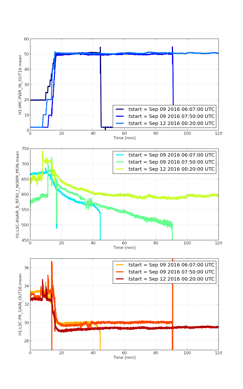
The mystery about AS 90 WFS may be (partially) due to the drift of dark offset.
We checked a time of today when IMC-MC2_TRANS_SUM was 0, and found that the output of a segment of AS 90 WFS was as large as ~100 cts when it was dark. As a comparison, the total sum of 4 segments at DC_readout was ~ 1000 cts. After corrected for it, the AS 90 WFS signal looked more reasonable.
We then checked the dark offset of the same WFS roughly days ago, and found that it drifted by ~ 100 ct (see, e.g., two seg1s in the attached plots). This large drift seemed make it not a very reliable sensor as the drift of dark offset was at least comparable to the signal we looked for. If we wanted to use it, we might have to check the offset frequently.
I looked at the dark offset drift of the AS 90 signals over several hours Monday night, when the PSL was shuttered. The dark offset for AS 90 signals jump around by a few tens of counts, even though the amount of light into the vacuum is not changing. Over the same period, the AS 36 and AS45 signals are stable to within one count. When we are at the Increase Power step of lock acquisition, the signals change from ~100 counts to several hundred counts when the power is changed from 2W to 8W, so these offset jumps are 10% or more of the signal size. Seems no good.
I only looked at the AS_A signals for this time stretch, but I have no reason to suspect that AS_B will be any different. Note that the last ~hour and a half of this time stretch the cleaning crew was working on getting HAM6 ready for the vent, so it's not surprising that we see offset changes, since we know that happens any time anyone is near the HAM6 racks.
Krishna, Michael This morning we stopped pumping on the BRS-2 to add a ~0.57 g washer to the top of the balance which shifted the COM up by ~10 microns. We then resumed pumping and remeasured the transfer function using the piezo stacks we installed yesterday. The attached plot shows the results of the measurements along with the model assuming d=0 microns and d=+/-1 microns. Plan for tomorrow: 1. Stop pumping with cart and switch to ion pump 2. Remove piezo stacks 3. Install thermal insulation
Changing the Section to SEI and tagging SEI in this. Let us take a second to appreciate this entry (and its companion, LHO aLOG 26298) -- The new-and-improved measurement technique is precise enough to measure the "d," (the separation between suspension point and center of mass) to better than a 1 [um] (recall that with BRS1 we were only able to get -35 +/- 5 microns; see e.g. LHO aLOG 13563)! That means we'll get excellent translation rejection from this rotation sensor. Nice work gents!
Vern, Fil, Nutsinee
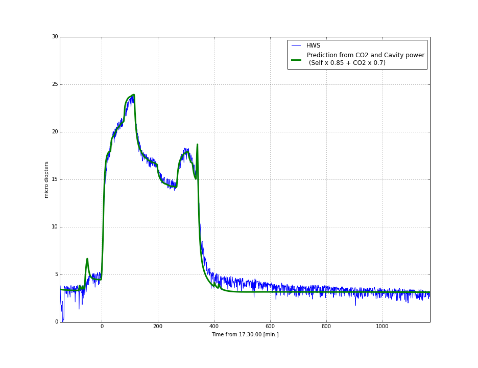
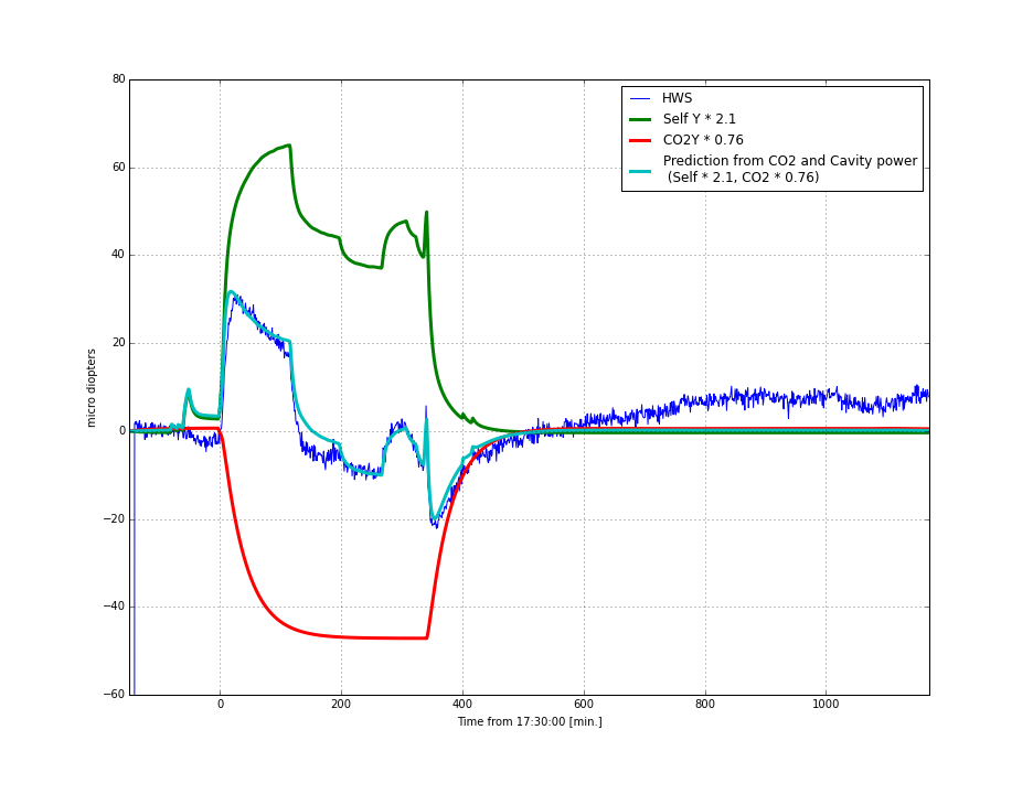
From the rotation stage random walk study we found that CO2Y rotation stage is off by ~30 deg when it's not behaving properly. Today we did some more test to narrow down the source of the problem and attempted to fix the problem. Turns out swapping out the rotation stage isn't as straight forward as I first thought so we went for less complicated approaches.
First we went out to the Ethercat chassis and look at the CO2Y rotation stage signal with an oscillascope while running the random walk script. The signal looked fine (Vern has the data saved in a floppy disk).
Then we swapped the sensing and motor cables such that CO2X software controls CO2Y rotation stage and CO2Y software controls CO2X rotation stage. This time CO2Y rotation stage behaved nicely and CO2X jumped. Attachment 1 shows CO2Y requested angle vs. measured angle and the differences. The data took after cable swap is plotted in cyan. Attachment 2 shows the same thing for CO2X. The jumpy red plot is the CO2X rotation stage data took after the cable swap (controlled by CO2Y software). Attachment 3 is CO2 power plotted against the requested angles. We concluded that the problem must be related to the software.
We planned to replace two things in the chassis: the CO2Y interface card (D1300131) and the dual motor controller (EL7342). After swapping the cables back in place, we replaced the CO2Y interface card (only). We also found lose connections in many places inside the chassis while doing the work so next Tuesday that chassis gonna have to come down so Fil can take a closer look. Anyway, swapping the interface card seems to have made the problem worse. Both rotation stages are now very jumpy, they have trouble going to negative requsted angles, and the measured angle goes beyond +-90 degrees. We were able to put the both CO2 power back to where they were before we started our work this morning but I wouldn't commission them at this point. The work is to be continued.
Note, for the record (and for the future), this ethercat chassis controls the PSL/IO rotation stage as well, so this work mucked with it as well which was surprising to the control room at the time. Now we know.
Today, I was planning to introduce the LASER_PWR Guardian node and the management changes in ISC_LOCK and ALIGN_IFO that would go along with it, but maintenance day got in the way. The LASER_PWR node seemed to work well and I thought I ironed out the small issues I had with the management, but I had not made it all the way through initial alignment before front ends started crashing and the PSL went down. I reverted to the copies in the svn just before I began my work (I committed before I started in case something like this happened), and it seems to all be back to mornal.
I'm leaving the LASER_PWR node alive, but stopped.
WP 5799 FR 4694 (PKA II 1193)
Continuing the offload of SUS calculating the SUSPOINT motion from ISI GS13 cartesian motion, this has ISI doing the calculating. We'll stop the SUS doing the calcs as soon as we confirm that DetChar is happy with the ISI numbers.
All the HAM models were rebuilt & installed and FrontEnds restarted. safe and OBSERVE.snaps were checked and updated (lots of new channels.)
No issues with HAM ISIs reisolating.
Medm editing is ongoing for the SUSPOINT. Each medm is custom for the number of suspensions. HAM6 and HAM2 still need to be built.
Along these lines, the BSC Models were adjusted to put the SUSPOINT on IPC and at ENDY, the BRS was added as at ETMX.
SVN COMMITS:
hugh.radkins@opsws1:models 0$ svn commit -m "HAM SUSPOINT calcs moved to ISI and BSC SUSPOINT calcs added to IPC and BRS at ETMY"
Sending models/h1isibs.mdl
Sending models/h1isietmx.mdl
Sending models/h1isietmy.mdl
Sending models/h1isiham2.mdl
Sending models/h1isiham3.mdl
Sending models/h1isiham4.mdl
Sending models/h1isiham5.mdl
Sending models/h1isiham6.mdl
Sending models/h1isiitmx.mdl
Sending models/h1isiitmy.mdl
Transmitting file data ..........
Committed revision 12961.
hugh.radkins@opsws1:models 0$ pwd
/opt/rtcds/userapps/release/isi/h1/models
hugh.radkins@opsws1:hamisi 0$ svn commit -m "Added suspension OPTICs for medm generation"
Sending hamisi/H1_isiham2_overview_macro.txt
Sending hamisi/H1_isiham3_overview_macro.txt
Sending hamisi/H1_isiham4_overview_macro.txt
Sending hamisi/H1_isiham5_overview_macro.txt
Sending hamisi/H1_isiham6_overview_macro.txt
Transmitting file data .....
Committed revision 12962.
hugh.radkins@opsws1:hamisi 0$ pwd
/opt/rtcds/userapps/release/isi/h1/medm/hamisi
hugh.radkins@opsws1:burtfiles 0$ svn commit -m "Update snaps for SUSPOINT & commissioning"
Sending burtfiles/h1isibs_down.snap
Sending burtfiles/h1isibs_safe.snap
Sending burtfiles/h1isietmx_safe.snap
Sending burtfiles/h1isietmy_OBSERVE.snap
Sending burtfiles/h1isietmy_safe.snap
Sending burtfiles/h1isiham2_safe.snap
Sending burtfiles/h1isiham3_safe.snap
Sending burtfiles/h1isiham4_OBSERVE.snap
Sending burtfiles/h1isiham4_safe.snap
Sending burtfiles/h1isiham5_OBSERVE.snap
Sending burtfiles/h1isiham5_safe.snap
Sending burtfiles/h1isiham6_safe.snap
Sending burtfiles/h1isiitmx_safe.snap
Sending burtfiles/h1isiitmy_OBSERVE.snap
Sending burtfiles/h1isiitmy_safe.snap
Transmitting file data ...............
Committed revision 12963.
hugh.radkins@opsws1:burtfiles 0$ pwd
/opt/rtcds/userapps/release/isi/h1/burtfiles
I'll commit the medm adls once I'm finished with them.
A full description of the changes committed about can be found in G1600795.
J. Kissel, B. Weaver, H. Radkins, D. Barker, J. Batch Here's a list of all of the upgrades we were involved in today. There will be more details of the upgrade, more debugging, associated MEDM screen changes, svn commits, and other clean up tomorrow as we continue to explore what we've installed and debug. Bear with us, and thanks for your patience. 1) Fixed UIM coil driver path's automatic compensation bug by updating CD_STATE_MACHINE.c. See Int. Issue 1178. 2) Installed ISI GS13's projection to SUSPOINT Euler basis projection into the SEI models. See ECR E1600028. 3) Sent the Euler Basis Longitudinal DOF for each SUS involved in a cavity over various IPC (PCIE and RFM) and models (ISI, End-station PEM, H1OAF) to be collected in OAF. See ECR E1600028. 8) Removed the excess RFM channels from End-Station ALS models (noteably *not* the excess channels in the ISC models). This made room for 3). See LHO aLOG 25216 4) Added various rotational sensor correction paths to the BSC ISIs (GND BRS to ST1, and ST1 to ST2). (Prototyping, this stuff, no ECRs just yet) 5) Removed the L4C sensor correction path. See SEI aLOG 666 6) Added new infrastructure for the EY BRS. (Most Copied from EX, covered by ECR E1500246) 7) Reverted the BSC SUS's coil driver monitors to store the NOISEMON in the frames (and pushed the FASTIMON to the commissioning frames). Also, we put filter modules in front of the NOISEMONs (like was done for the FASTIMONs the last time we touched this) in case we ever wish to calibrate them. See ECR E1600033 and LHO aLOG 26313 Because we haven't built MEDM screens and actually *used* any of these paths yet, there's still potential for bugs and we haven't explored and/or fixed all of the collateral damage. Stay tuned as we continue to work on all of these updates tomorrow.
J. Kissel I've documented all of the front-end model changes that were necessary for items 2, 3, 5, 6, and 7 (i.e. all of the SEI model changes). Check out G1600795. As indicated in LHO aLOG 26321, all of the simulink model changes have been committed to the repository.
J. Kissel, H. Radkins Here're the updated MEDM screens that correspond to the above SEI model updates. I'll work on the Cavity Basis OAF MEDM screen tomorrow. The following screens where changed and/or added: /opt/rtcds/userapps/release/isi/common/medm/bscisi A ISI_CUST_CHAMBER_ST1_ROT_SENSCOR_FIR_ALL.adl A ISI_CUST_CHAMBER_ST1_ROT_SENSCOR_IIRHP_ALL.adl A ISI_CUST_CHAMBER_ST1_ROT_SENSCOR_MATCH_ALL.adl A ISI_CUST_CHAMBER_ST2_ROT_SENSCOR_FIR_ALL.adl A ISI_CUST_CHAMBER_ST2_ROT_SENSCOR_IIRHP_ALL.adl A ISI_CUST_CHAMBER_ST2_ROT_SENSCOR_MATCH_ALL.adl Sending ISI_CUST_CHAMBER_ST1_SENSCOR_OVERVIEW.adl Sending ISI_CUST_CHAMBER_ST2_SENSCOR_OVERVIEW.adl Sending ISI_CUST_CHAMBER_OVERVIEW.adl=
18VDC power cables are in pplace and terminated in the corner station. The BS oplev power cable is not yet installed.
Fil and I ran and terminated the BS OpLev pwr cable today.
Flip flopping between the need to use FASTIMONs OR NOISEMONS for a variety of commissioning or DETCHAR reasons (but not being able to support both sets of channels) today we reverted a small portion of the work towards integrating the FASTIMONs into QUAD-land from alog 25329. Today we put the NOISEMONs back into the BS and QUAD models, keeping their original data rates and made the FASTIMONS commissioning frames only. This required restarts of the h1susauxb123, h1susauxex, and h1susauxey computers.
The SUS AUX Channel Monitor medms then had broken links which I partially fixed. I fixed the readback channel, but the long colored bit thing associated with every one of these channels (holds the same info as the read back) is a pain in the whooo to change so will have to wait until I can regrow some patience.
I've committed these SUSAUX model changes and medm edits to SVN.
I took charge measurements at both ends today, they finished around 12:50 local. I'll post plots soon.
The four plots are here
There were a few weeks that were not placed into the long trend, but a large majority of the data seems to be bad. I took out what I saw was obviously bad but the error bars are still huge on many of the points. Plots are attached but it definitely needs a second look hopefully tomorrow.
Note, I think it is time to change the sign on both of these ETM ESDs. The ETMx has now migrated ~20-30 volts away from 0, albiet at a slow rate. The ETMY sign flip from last month needs to be investigated since it seems that charge is still growing (slowly) there. More to follow.
Kiwamu, Stefan
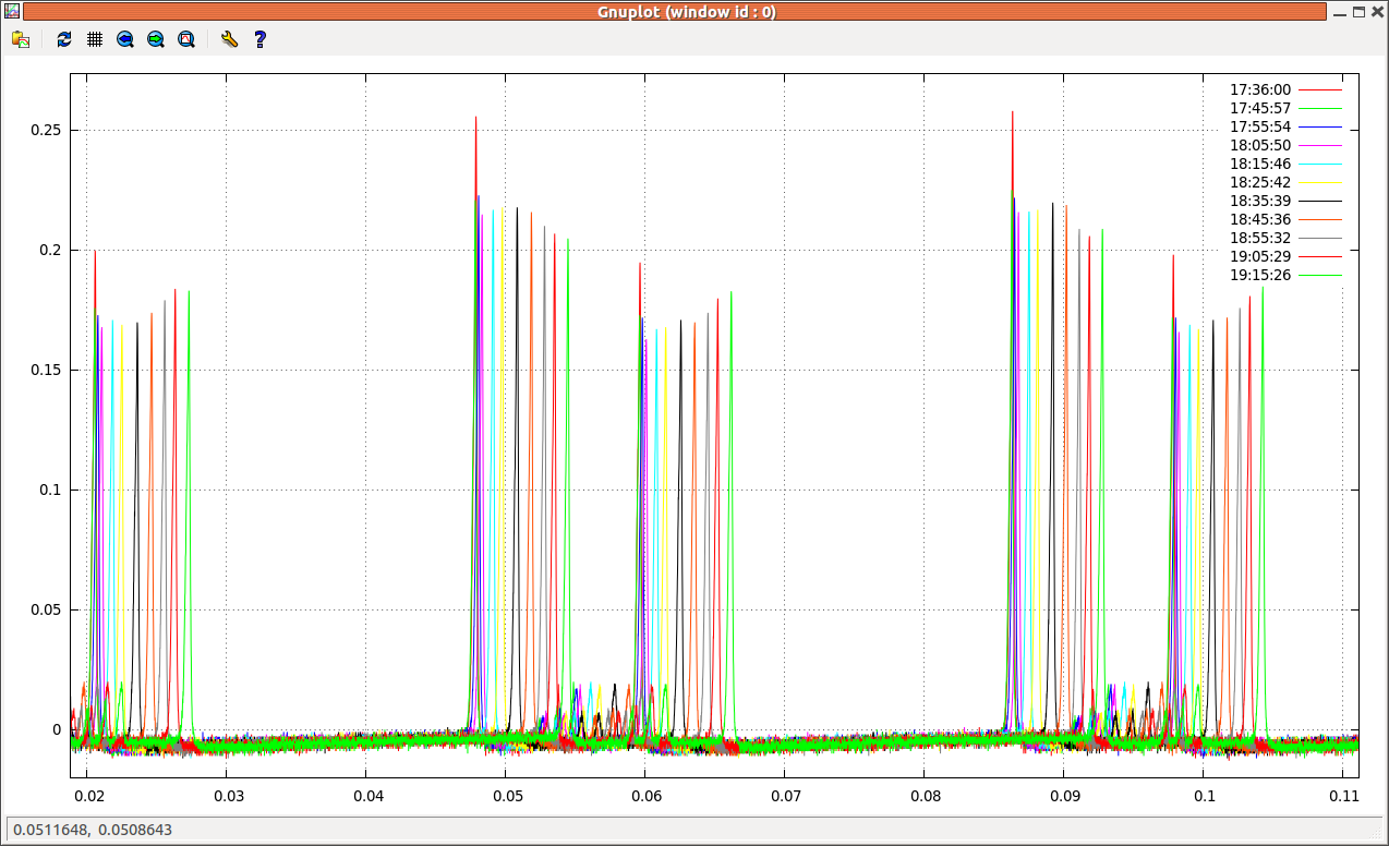
Looking at the cross-power plot in alog 25768, we see a coherent noise floor following the shot noise a factor 3.3 below.
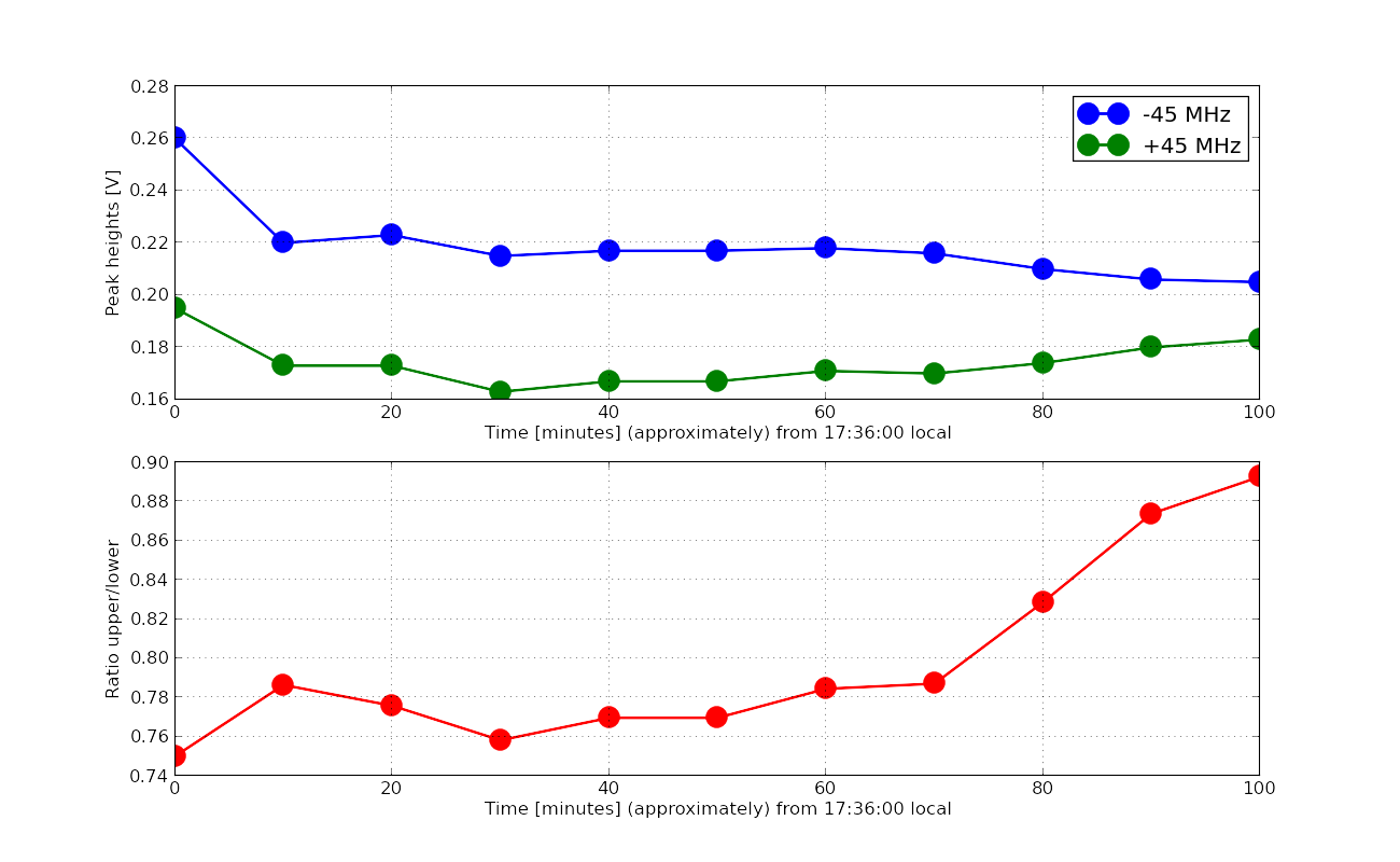
Looking at alog 21167, this seems cosistent with our old firend the excess 45.5 MHz noise in DARM.
Shot noise of 20mA: 8e-8mA/rtHz: a factor of 3.3 below that: 2.4e-8mA/rtHz. This is roughly consistent with the residual coherence seen in alog 21167.
Kiwamu will make an all-O1 plot to nicely resolve that noise. We need to add this noise to the mystery noise projection in alog 25106 (this plot).
Here is a cross-spectrum with more number of averaging (over 867 hours using the data between Oct-21-2015 to Jan-17-2016 with some glitchy durations excluded).
I looked at some few-hour stretches of O1 data and took the coherence between the DCPDs.
Above 1 kHz (where the DARM OLTF is −55 dB or less), the coherence goes as low as 1×10⁻⁴. See attachment for an example; FFT BW is 2 Hz and number of averages is >50,000. That would imply a correlated DCPD sum noise that is a factor of 7 below the shot noise [since the correlated noise ASD in each PD should be (1×10⁻⁴)1/4 = 0.1 relative to the uncorrelated (shot) noise ASD].
I suppose it is possible that the secular fluctuations in the nonlinear 45 MHz noise are enough to push the overall O1 coherence up to 2×10⁻³, which is what is required to achieve a correlated noise that is a factor of 3.3 below the shot noise in the DCPD sum.
To test this, I propose we look at the variation over O1 of some kind of BLRMS of the 45 MHz EOM driver control signal (or perhaps just the dc level of the control signal), similar to what Kiwamu has already done for some of the suspension channels.
During this same time period, the excess of sum over null above 1 kHz is about 0.1×10⁻⁸ mA/Hz1/2. Assuming 8×10⁻⁸ mA/Hz1/2 of null current therefore implies the correlated excess is a factor of 6 to 7 below shot noise.
(The slope in the data is probably from the uncompensated AA filtering).
The second attachment shows the conversion of the sum and null into equivalent freerunning DARM. From the residual alone, the limit on the coating Brownian noise seems to be a factor of 1.6 above nominal. (I quickly threw in a 5 kHz zero when undoing the loop in order to compensate for the AA filtering).
Finally, I add some mystery noise traces to this residual, where the slopes and amplitudes have been arrived at by careful numerology. The addition of a 1/f2 noise and a mystery white sensing noise (similar to 26004, but tuned to the residual during this time period) reduces the possible coating Brownian excess factor to 1.45 or so.
Here is an updated version of the cross spectrum using the O1 data. I have fixed a bug which previously overestimated the cross specctrum and have extended the analysis to high frequencies above 1 kHz.
As pointed out by Evan, my previous analysis overestimated the correlated noise. This turned out to be due to a bug in my code where I summed the absolute value of the segmented cross spcetra when averaging them. This is apparently wrong because the cross spectra by nature can have negative value (and imaginary number). I fixed the analysis code and reran the analysis again. The result looks consistent with Evan's targeted cross spectrum -- the kink point of the cross correlation happenes at around 1 kHz with the noise floor touching 1e-20 m/sqrtHz.