Summary- the sensing sign in the online calibration for SRCL has been wrong.
This has been causing overestimated noise in 10 - 100 Hz in the past years(!). My bad. This is now fixed.
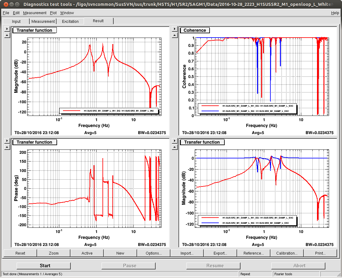
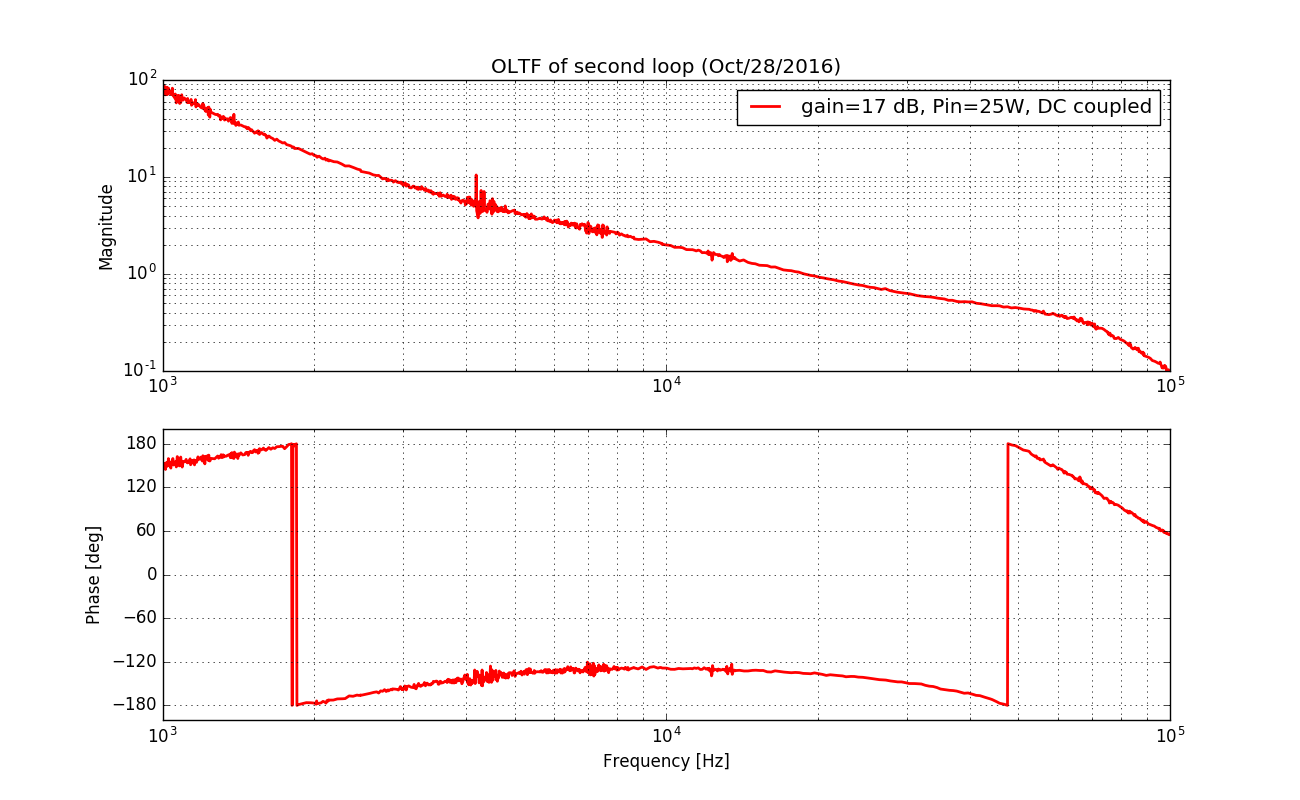
Details- Daniel and Stefan a week or two ago told me that changing the shape of the digital filter in SRCL affected the calibrated SRCL displacement spectrum. This statement made me suspect that something was wrong in the online calibration or aka CALCS. Today, I have re-measured the SRCL open loop gain in nominal low noise with an input power of 25 W. A plot of the open loop is attached in this etnry. The absolute value of the SRCL sensing was found to be the same. However, the measurement indicated that the sensing gain should be a negative number (dP/dL < 0 or smaller counts as the SRC length expands). This contradicted with what we have had in CALCS where the sensing was set to positive. This is very simillar to what we had in the online DARM calibration (29860), but this time SRCL has been wrong for years.
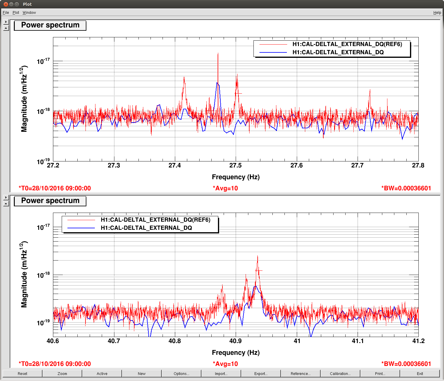
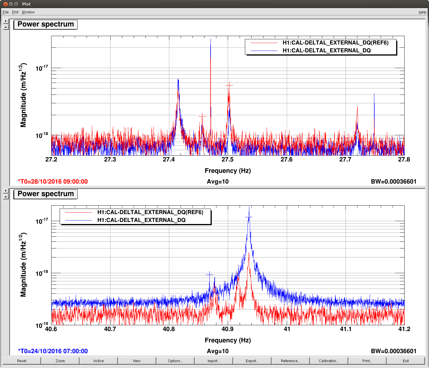
Flipping the sensing gain in CALCS (so as to match the sign with the measurement) decreased the noise level in the online monitor by a factor of 2 at 60 Hz in 10 - 100 Hz. You can see the difference below.
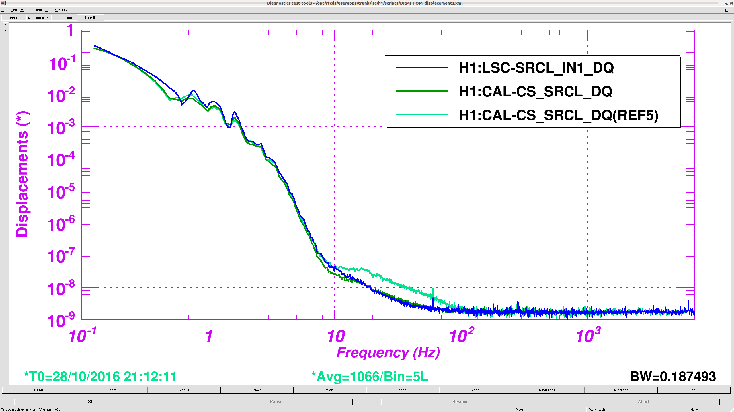
The cyan is before the sign flip in CALCS, and the green is after. In order to double check the validity, I produced the calibrated spectrum only using SRCL_IN1 (blue) which agreed with the online calibration. There is small discrepancies between SRCL_IN1 and CAL-CS by a few % which, I believe, is due to the fact that we don't take the time delay of the system into account in CAL-CS. The sign flip is now implemented by adding a minus sign in FM1 of CAL-CS_SUM_SRCL_ERR (which is now a scaler value of -9.55e-6). I did not change the absolute value.
Additionally, I looked at some calibration codes that I made some time ago (18742) and confirmed that I mistakenly canceled the minus sign in the sensing gain of the model. Also, according to the guardian code ISC_LOCK and trend data, the sign of the SRCL servo gain in LSC or the relevant filters in the SUS SRM did not change at least in this past year. I am fairly sure that this calibration has been wrong for quite some time.
The relevant items can be found at the following locations.
Open loop measurement: /ligo/svncommon/CalSVN/aligocalibration/trunk/Runs/PreER10/H1/Measurements/LscDrmi/SRCL_oltf_25W_20161028.xml
Open loop analysis code: /ligo/svncommon/CalSVN/aligocalibration/trunk/Runs/PreER10/H1/Scripts/LscDrmi/H1SRCL_OLTFmodel_20161028.m
Plots for open loop: /ligo/svncommon/CalSVN/aligocalibration/trunk/Runs/PreER10/H1/Results/LscDrmi/2016-10-28_SRCL_openloop.pdf
/ligo/svncommon/CalSVN/aligocalibration/trunk/Runs/PreER10/H1/Results/LscDrmi/2016-10-28_SRCL_openloop.png


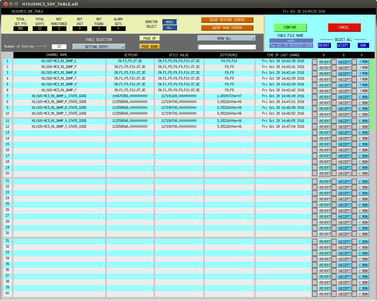


if guardian is controlling the gain, perhaps sdf shouldn't be monitoring it.