jeffrey.kissel@LIGO.ORG - posted 19:33, Monday 07 November 2016 (31300)
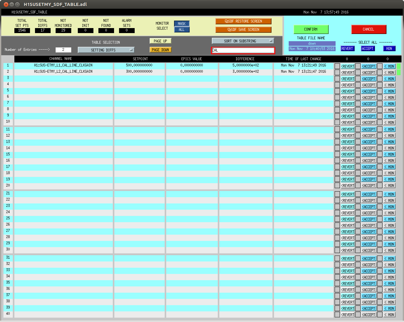
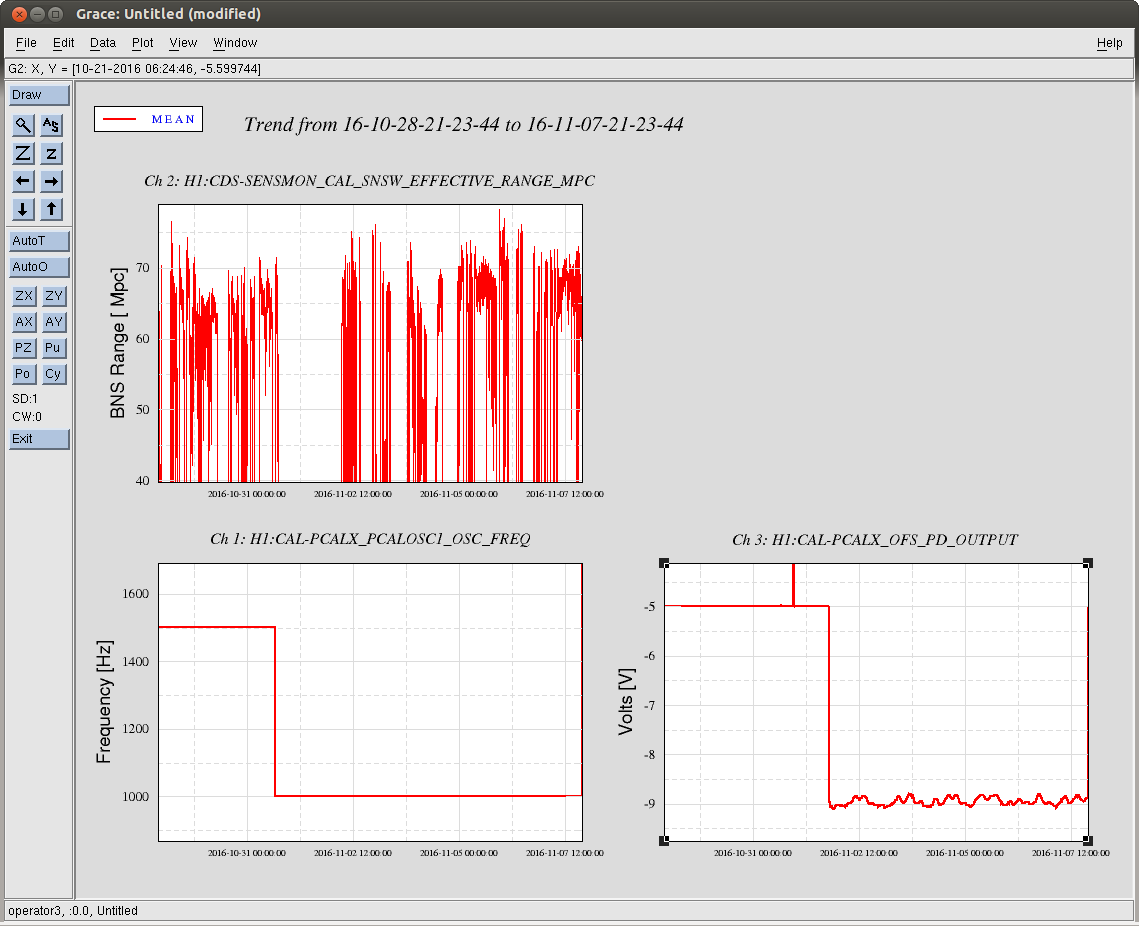
PCALX Roaming Calibration Line Frequency Changed to 4001.3
J. Kissel

The duty-cycle has been delightfully high, so we've been able to get the two hours needed for 1001.3 Hz data point of the roaming high-frequency calibration line quickly despite this mornings issues (see LHO aLOG 31288). Thus, I'm changing it to the much more time intensive 4 kHz line.

Here's the latest status:
Frequency    Planned Amplitude        Planned Duration      Actual Amplitude    Start Time                 Stop Time                    Achieved Duration
(Hz)         (ct)                     (hh:mm)                   (ct)               (UTC)                    (UTC)                         (hh:mm)
---------------------------------------------------------------------------------------------------------------------------------------------------------
1001.3       35k                      02:00                   39322.0           Nov 11 2016 21:37:50 UTC    Nov 12 2016 03:28:21 UTC      ~several hours @ 25 W
1501.3       35k                      02:00                   39322.0           Oct 24 2016 15:26:57 UTC    Oct 31 2016 15:44:29 UTC      ~week @ 25 W
2001.3       35k                      02:00                   39322.0           Oct 17 2016 21:22:03 UTC    Oct 24 2016 15:26:57 UTC      several days (at both 50W and 25 W)
2501.3       35k                      05:00                   39322.0           Oct 12 2016 03:20:41 UTC    Oct 17 2016 21:22:03 UTC      days     @ 50 W
3001.3       35k                      05:00                   39322.0           Oct 06 2016 18:39:26 UTC    Oct 12 2016 03:20:41 UTC      days     @ 50 W
3501.3       35k                      05:00                   39322.0           Jul 06 2016 18:56:13 UTC    Oct 06 2016 18:39:26 UTC      months   @ 50 W
4001.3       40k                      10:00                   39322.0           Nov 12 2016 03:28:21 UTC
4301.3       40k                      10:00
4501.3       40k                      10:00
4801.3       40k                      10:00
5001.3       40k                      10:00
Images attached to this report