TITLE: 11/02 Owl Shift: 07:00-15:00 UTC (00:00-08:00 PST), all times posted in UTC
STATE of H1: Lcok Acquisition
INCOMING OPERATOR: Patrick
SHIFT SUMMARY: Bad. All locklosses tonight were caused by PI 18043Hz (Mode27). See alog31111 and comments therein. There were 6 locklosses total. I didn't keep track of all the lockloss times. None of the modes were PLL locked but only one or two casued trouble. Mode 26 also rung up but was able to damp once I get the BP filter to match the peak frequency. Not as straight forward for Mode 27.
LOG:
08:50 Lockloss
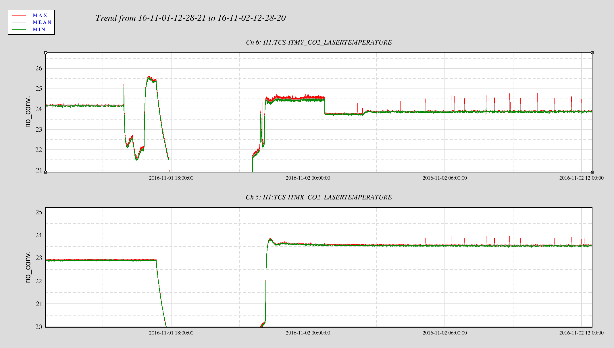
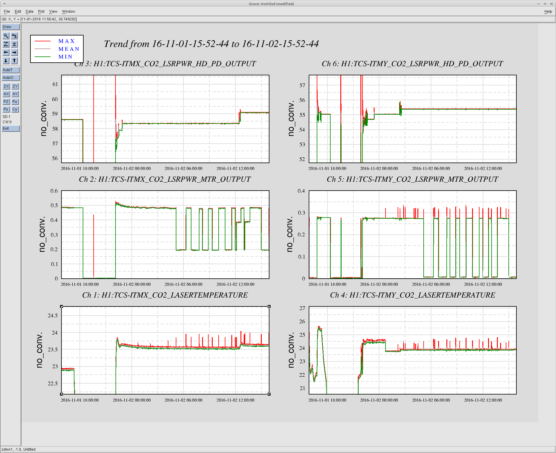
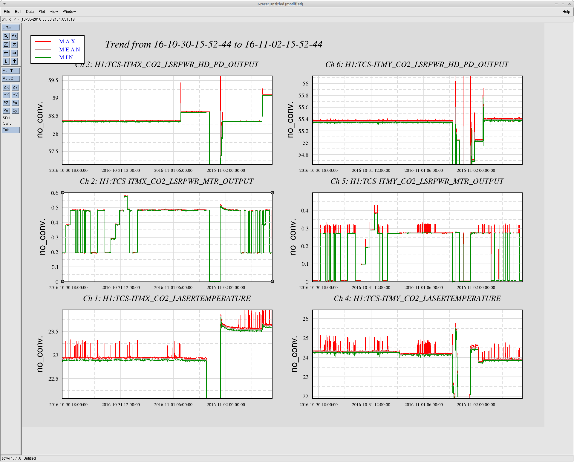
12:06 CO2X 0.2W --> 0.4W
12:09 Intent bit set
12:25 Intent bit dropped. CO2X Guardian finds lock point
12:32 Intent bit dropped. CO2X Guardian finds lock point
12:37 Lockloss
13:05 NLN. CO2X 0.2W --> 0.4W
13:39 Lockloss. Peter wants to make some measurement with the PSL so I kept the IFO down.
14:34 Peter out
Note:
-
I also removed I_M saturation warning from the Verbal Alarm script (line 244, I_M=104) so I can listen to something else that's actually important. It got to the point where the alarm would complains every 2 seconds even at NLN. IM3 was saturating but wasn't causing locklosses. I tried clearing history but it didn't help. I guess somebody will have to move it before the next initial alignment.
-
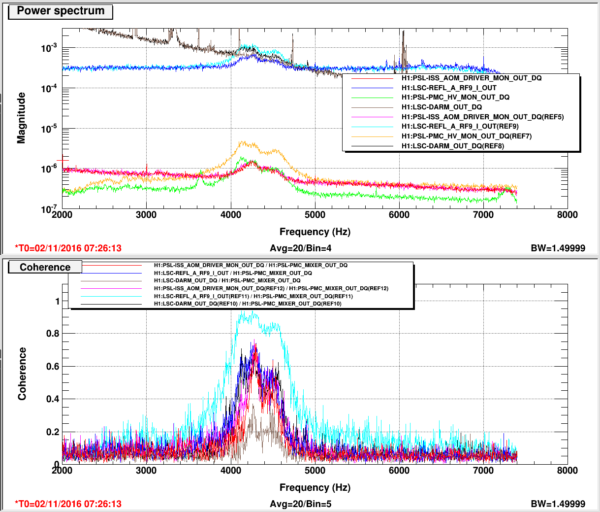
First half of the night I tried to make some injection so I can measure frequency noise TF. But since I'm a noob I was able to make DARM spectrum rise only at f>1000Hz and not the entire frequency range. I quit after PI became a consistent issue