gerardo.moreno@LIGO.ORG - posted 16:16, Monday 31 October 2016 (31045)
CP3 Manual Overfill at 22:50 utc
Took 4 minutes 42 seconds to overfill CP3 with LLCV bypass valve 1/2 turn open.
Took 4 minutes 42 seconds to overfill CP3 with LLCV bypass valve 1/2 turn open.
J. Kissel
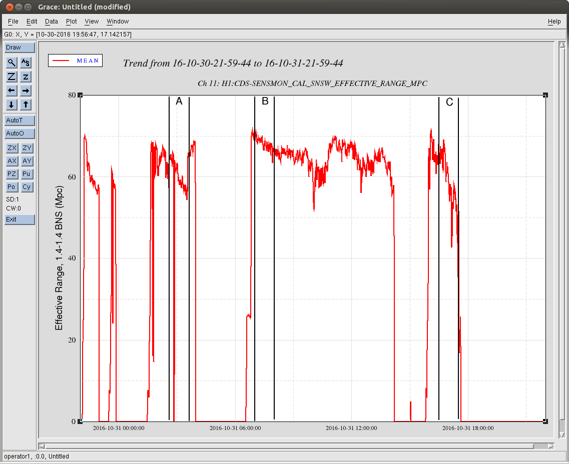
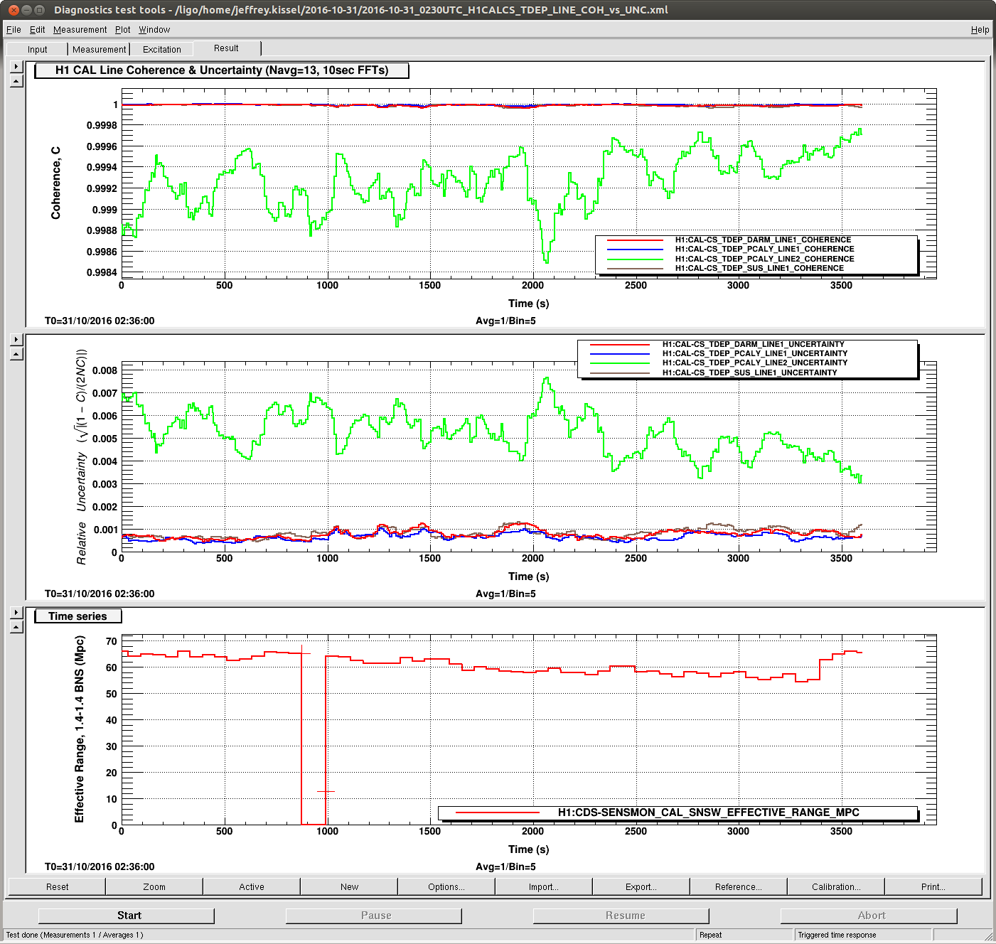
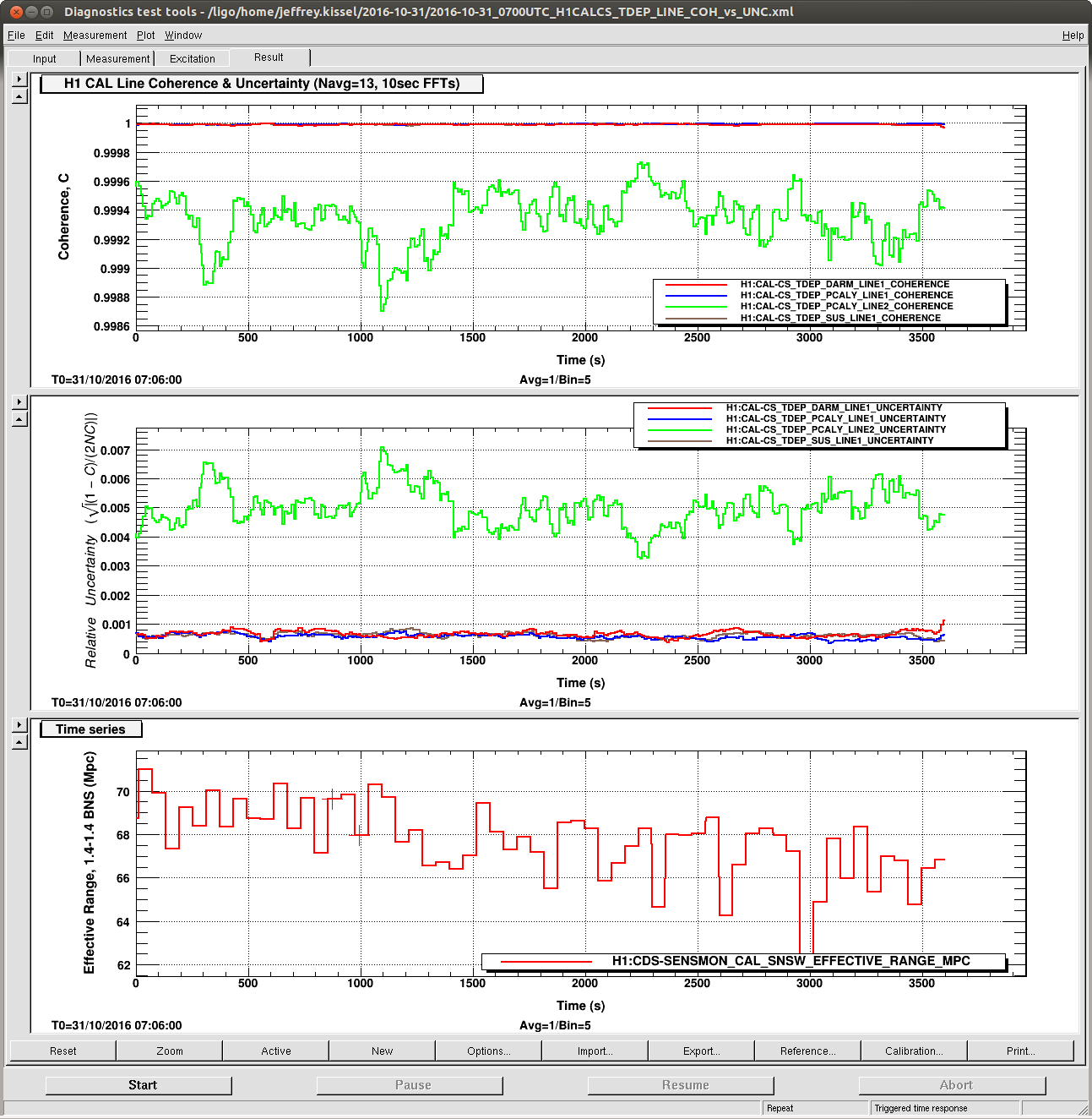
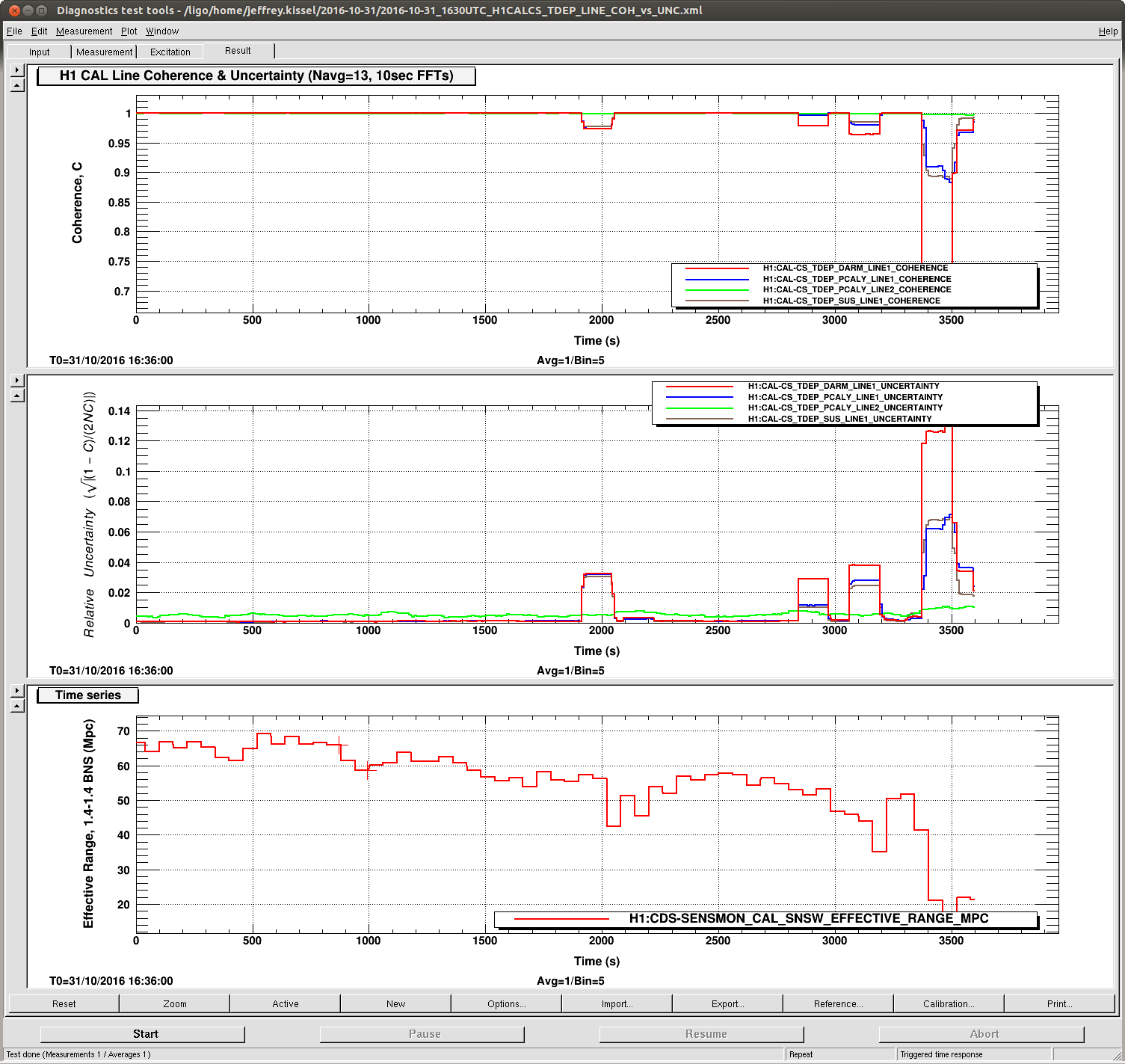
We're exploring the functionality of the new features of the front-end calibration that calculates the coherence and subsequent uncertainty of the transfer function between each CAL line source and DARM. As such, I plot three, one-hour data stretches from different lock stretches in the past 24 hours.
Data Set A: 2016-10-31 02:30 UTC
Data Set B: 2016-10-31 07:00 UTC
Data Set C: 2016-10-31 10:00 UTC
Note the translation between channel names and to which line they're analyzing:
H1:CAL-CS_TDEP_..._[COHERENCE/UNCERTAINTY] Frequency Used In Calculating
DARM_LINE1 37.3 kappa_TST (ESD Actuation Strength)
PCAL_LINE1 36.7 kappa_TST & kappa_PU (ESD and PUM/UIM Act. Strength)
PCAL_LINE2 331.9 kappa_C & f_C (Optical Gain and Cavity Pole)
SUS_LINE1 35.9 kappa_PU (PUM/UIM Act. Strength)
where you can refer to P1600063 and T1500377
Recall also, that our goal is to have the uncertainty in the time-dependent parameters (which are calculated from combinations of these lines) to around ~0.3-5%, such that these uncertainties remain non-dominate (lines are strong enough), but non-negligible (not excessively strong). An example total response function uncertainty budget in LHO aLOG 26889, to see at what level the time-dependent parameter estimation uncertainty impacts the total uncertainty. That means the uncertainty in each line estimate should be at the 0.1-0.3% level if possible. So, we can use these data sets to tune the amplitude of the CAL lines, so as to optimize uncertainty needs vs. sensitivity pollution.
There are several interesting things. It's best to look at the data sets in order B, then A, then C.
In data set B --
- this is what we should expect if we manage to get a stable, O1-style interferometer in the next week or so for ER10 and O2.
- With the current amplitudes, the uncertainty on the ~30 Hz lines hovers around 0.1% -- so we can probably reduce the amplitude of these lines by a factor of a few if the sensitivity stays this high.
- The 331 Hz line amplitude should probably be increased by a factor of a few.
In data set C -- (this is during the ghoulish lock stretch)
- One can see when the data goes bad, it goes bad in weird, discrete chunks. The width of these chunks is 130 sec (almost exactly), which I suspect is a digital artifact of the 13 averages and 10 sec FFTs. The sensitivity was popping, whistling, and saturating SUS left and right during this stretch, at a much quicker timescale than 100s of seconds.
In data set B --
- This is an OK sensivity stretch. The good thing is that the coherence/uncertainty appears to be independent of any fast glitching or overall sensitivity, as long as we stick in the 60-75 Mpc range.
- Interestingly, there's either a data dropout, or terrible time period during this stretch (as indicated by the BNS range going to 0) -- but it's only ~120 sec. If it's a data drop out -- good, the calculation is robust against whatever happens in DMT land. If it's a period of glitchy interferometer, it's very peculiar that it doesn't affect the uncertainty calculation, unlike with data set C.
Based on these data sets, I think it'll be safe to set the uncertainty threshold at 1%, and if the uncertainty exceeds that threshold, the associated parameter value gets dumped from the calculation of the average that is applied to h(t).
So, in summary -- looks like the calculations are working, and their calculated value roughly makes sense when the IFO is calm. There're a few suspicious things that we need to iron out when the IFO isn't feeling so well, but I think we're very much ready to use these coherence calculations as a viable veto for time-dependent parameter calculations.
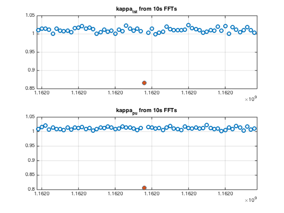
Jeff K, Darkhan T,
We investigated further the 130s drop in coherence in the data set C (see LHO alog 31040 above).
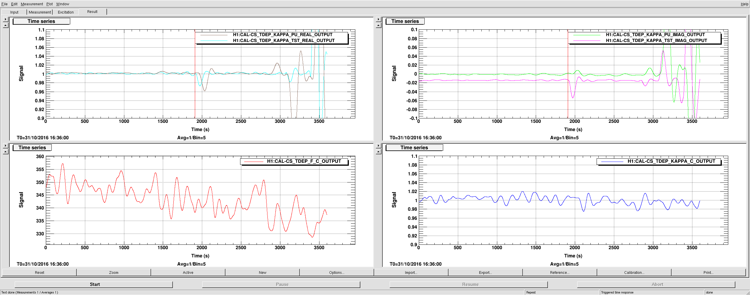
This drop was possibly caused by a bad data point(s) ("glitch") at the beginning of this drop (when first glitchy data point entered the 130s averaging buffer). A quick look at kappas calculated in PcalMon from 10s FFTs during 600s around time of the glitch indicates that outliers in κTST and κPU values are found only in one of the 10s intervals. This interval is GPS [1161968880, 1161968890) (see attachment 1).
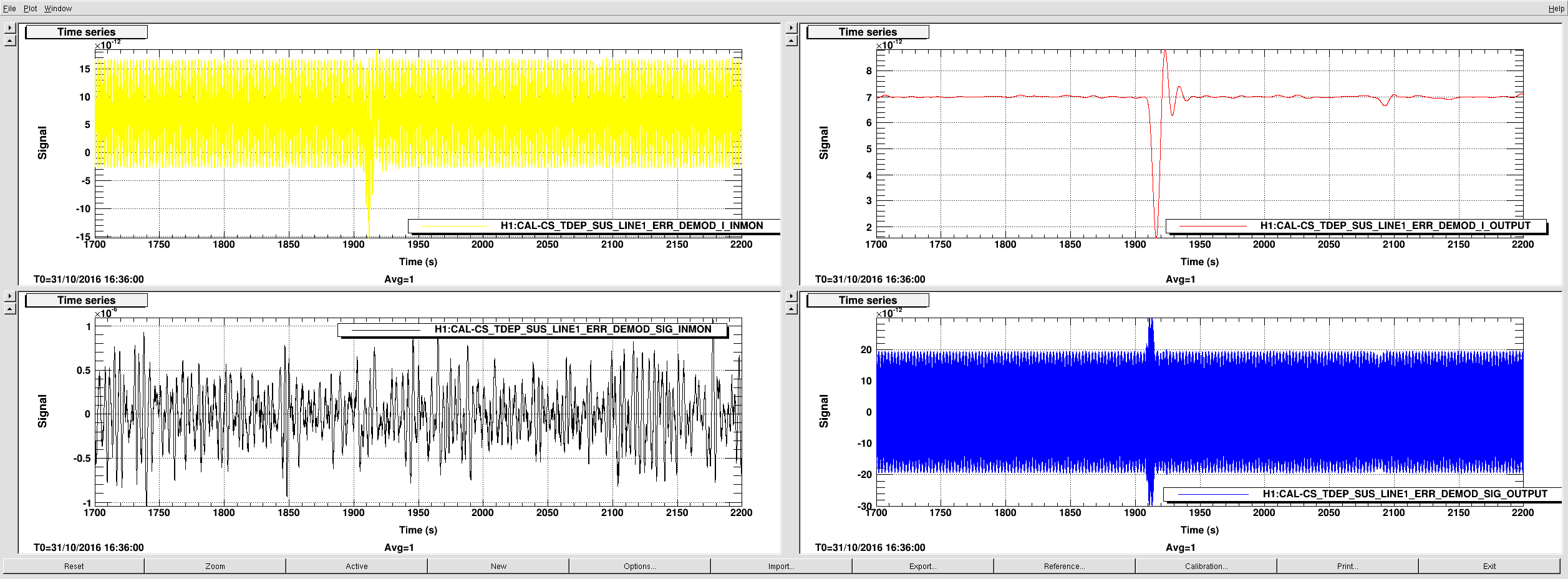
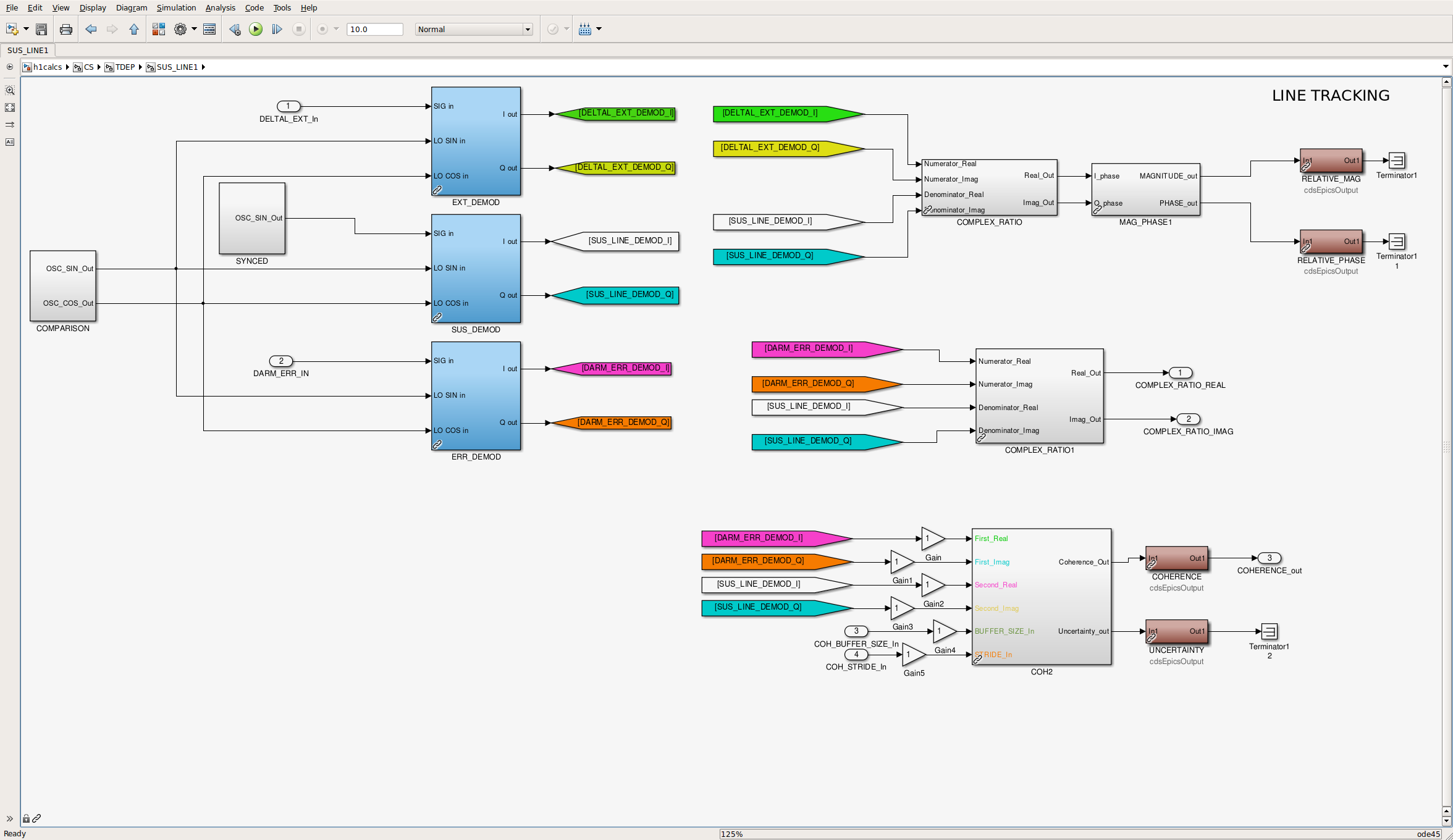
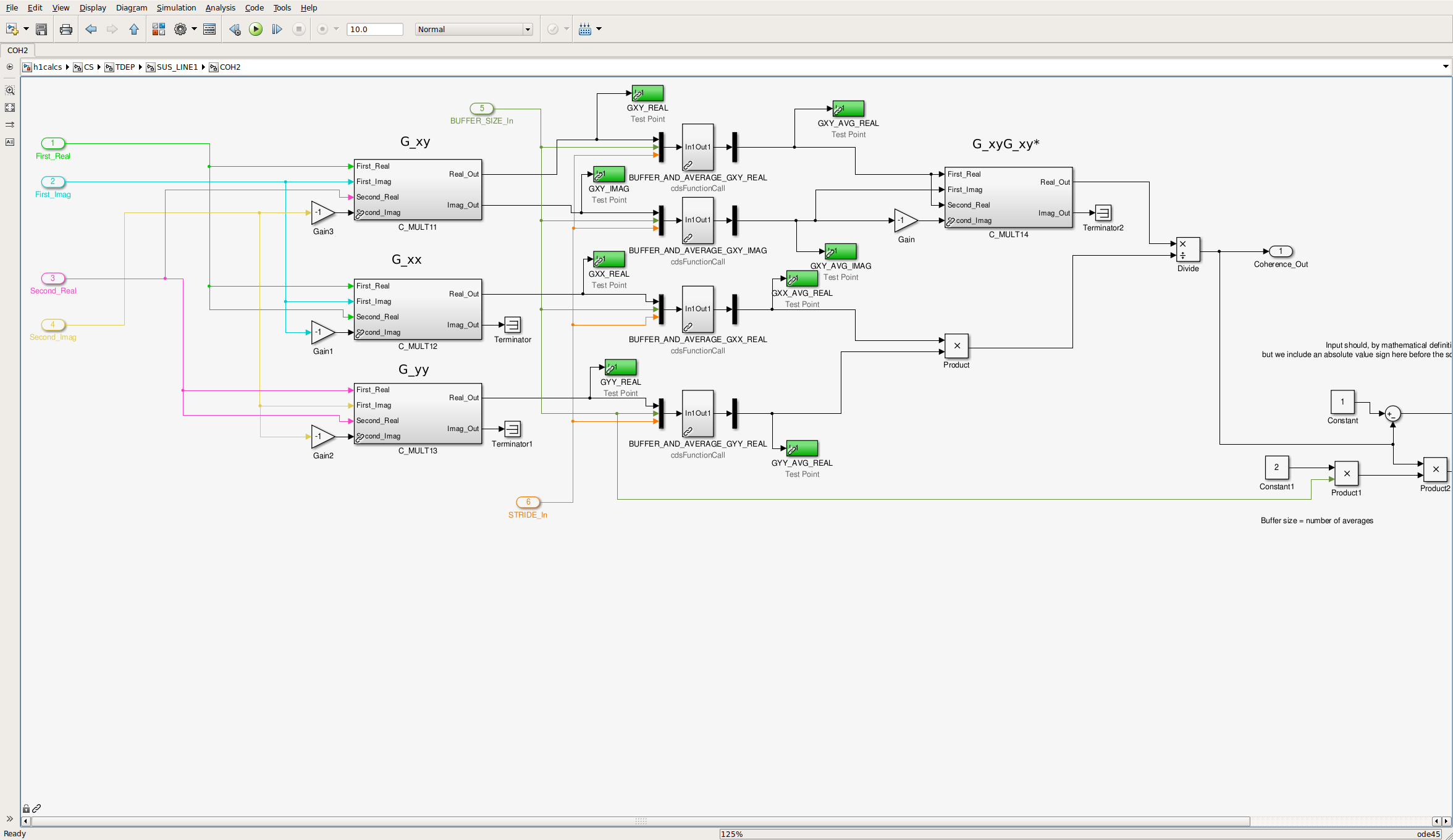
A look at slow channels indicate that the glitch produced impulse responses lasting just under 10s before 0.1Hz low-pass filter and roughly 30s after the filter, DARM_ERR demodulated at 35.9 Hz (see upper panes in attachment 2, ). Start of the glitch is at ~1910s (GPS 1161968887). In the coherence calculation block of the CAL-CS model (attachments 3 and 4), it can be seen that the glitch lasts 20-30s in EPICS records preceeding the 130s averaging blocks (BUFFER_AND_AVERAGE), but results in reduction of the calculated coherence value for 130s (see attachment 5).
If we use coherence values from the CAL-CS front-end model as a threshold for "bad kappas", this kind of glithces will result in unnecessarily marking 130s of kappas as "bad". GDS median kappas should not be sensitive to this kind of short glitches, however CAL-CS front-end κTST were affected for ~250s (front-end kappas are low passed with a 1/128 Hz IIR filter) (see attachment 5).
A potential (not yet tested) solution would be to replace BUFFER_AND_AVERAGE (running aveage) script with a running median. And a similar script can be used for averaging of the front-end kappas, which would also reduce discrepancies between GDS and front-end kappas.
Jeff, Dave:
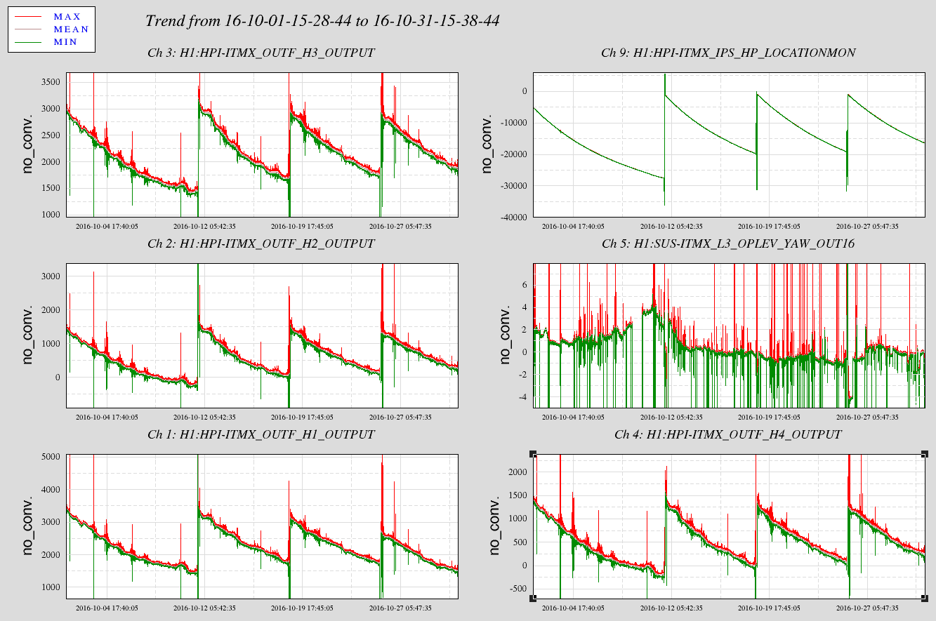
Following Jeff's SUS changes last tuesday (25th October) we have accrued enough data to report on changes to the frame size and sus front end cpu usage.
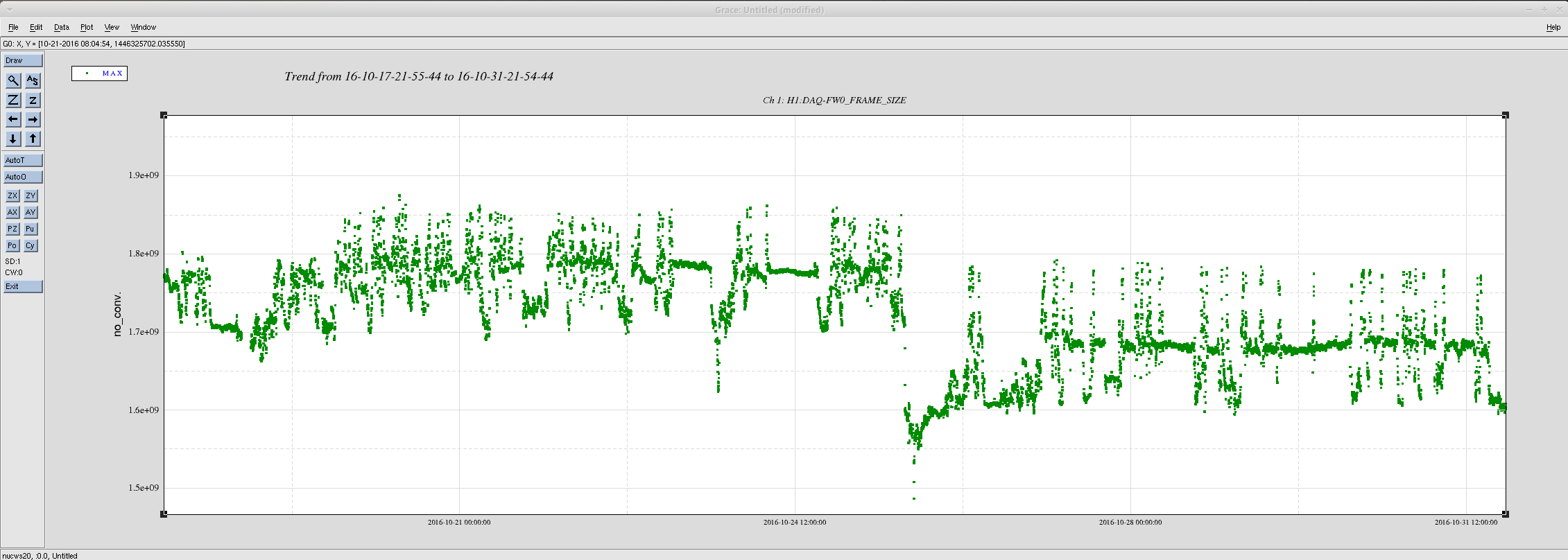
Attached is a two week trend of the full frame size. This is a compressed frame, so its size varies dependent upon the state of the interferometer. Drawing an average by eye, the 64 second full frame size has decreased from a mean value of 1.77GB to 1.67GB. This is a 6% disk/tape saving. It equates to a per-second data rate decrease of 27.7 MB/s to 26.1 MB/s (decrease of 1.6 MB/s).
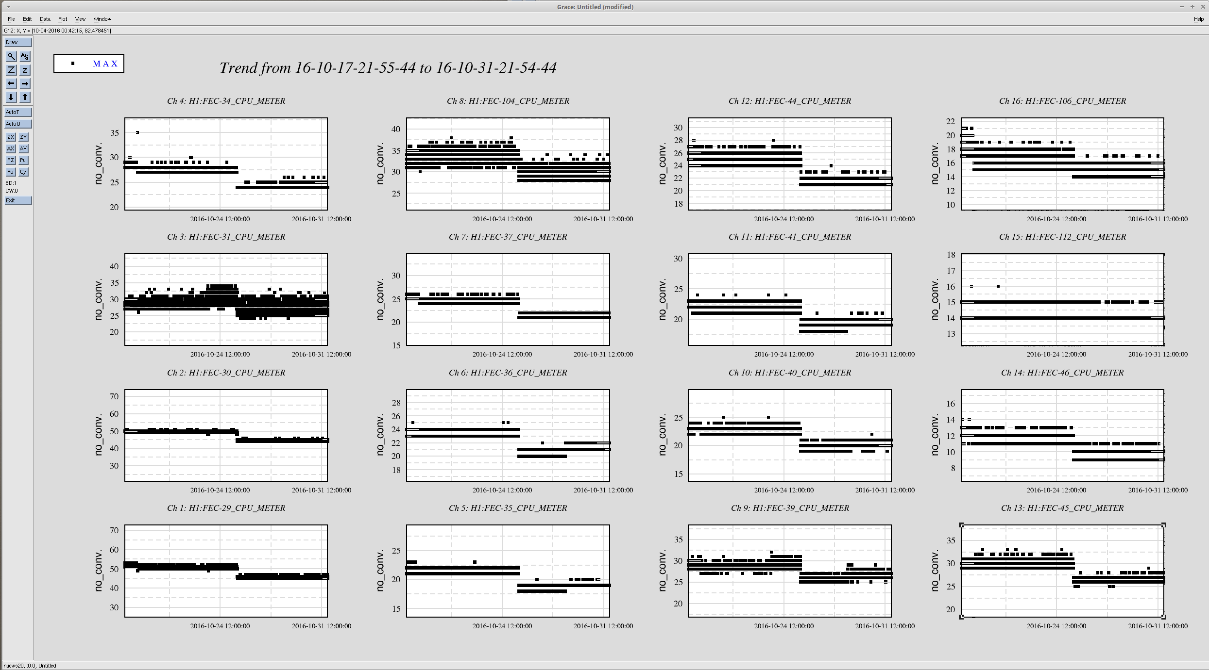
The removal of filters and reduction of DAQ channel decimation also improved the cpu processing time on most SUS models. The attached plot shows the 16 corner station sus and susaux models. They typically report an improvement in cpu time of 10%.
15:49 Jeff B to mid stations to check on 3IFO items
16:03 Cleaning crew into highbay area before the LVEA to get some C3 covers.
16:07 Intention bit set to UNDISTURBED
16:13 Intention bit reverted to COMMISSIONING mysteriously (it seems)
16:15 Intention bit reset to UNDISTURBED
16:25 Jeff B to EX TMS lab
16:54 Jeff B is back
17:50 IFO will be in DOWN fo the duration of the shift due to high winds
18:25 Travis, Darkhan and Yuki to EY for PCal calibrations
19:21 Sheila out to the LVEA to plaug in power monitors for ESD
20:11 Travis and co. back
21:14 Carlos to EY to take image of the HWS computer
21:25 BRS disabled at BOTH end stations now.
21:27 Robert into PSL enclosure
21:37 Peter out to the LVEA to trace out a cable
21:38 Sheila to end stations to plug in power mointors for ESD
21:42 Automated phone call about a malfunction in a Hanford alarm test. additional testing will be done between 2:45 and 3:45PM
21:53 Peter is back
22:00 Fil out to LVEA North bay to look for a rack stand
22:27 Sheila back.
I added two stages of whitening to the IMC REFL DC readback, so we are no longer ADC noise limited anywhere.
I also added a ct2mW filter based on the old calibration described here.
Attached is the last 2 months of relative humidity data from the desiccant cabinets in the VPW. Apparently the DB4 RH logger quit recording data sometime last month, so it is not attached. I'm looking into a replacement logger. If it's any consolation, when I've spot checked the RH reader periodically over the last month it has always been under 1%.
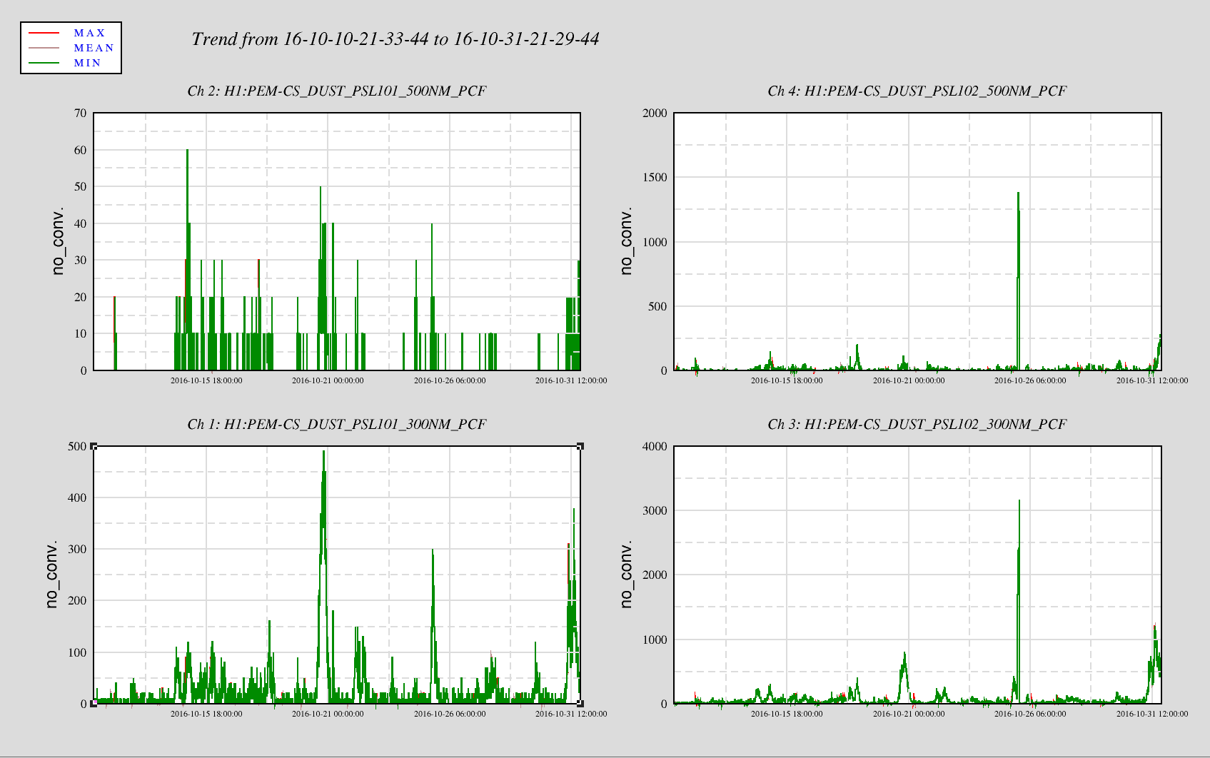
Peter K., Jeff B.

   Today there have been elevated dust counts in the PSL laser room and in the Anti-Room. Trends over the past few weeks show several spikes of high counts in both rooms.

   The alarm level settings for the Anit-Room (DM 102) are set for clean 1000 (Minor alarm 700 counts, Major alarm 1000 counts). The PSL enclosure is set for Minor alarm at 140 counts and major alarms at 200 counts.

   We are still looking into the cause of these spikes.

P.S. Ops - Please let me know if you are getting dust monitor alarms and what the wind is doing at the time of the alarms.
I changed to WINDY_NO_BRSX for PCal work at EX. I forgot to switch it off at EY for earlier work that was done but it appears to be ok down there.
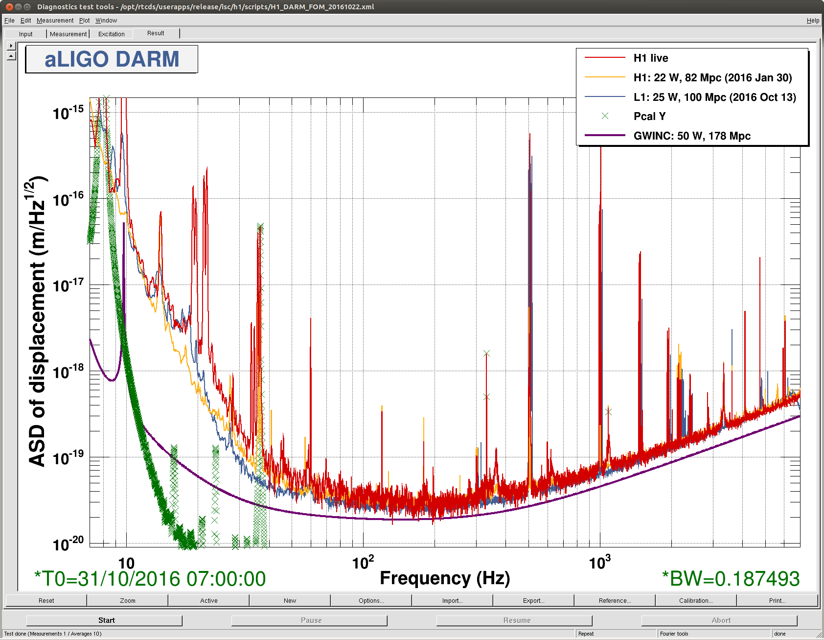
J. Kissel, E. Hall
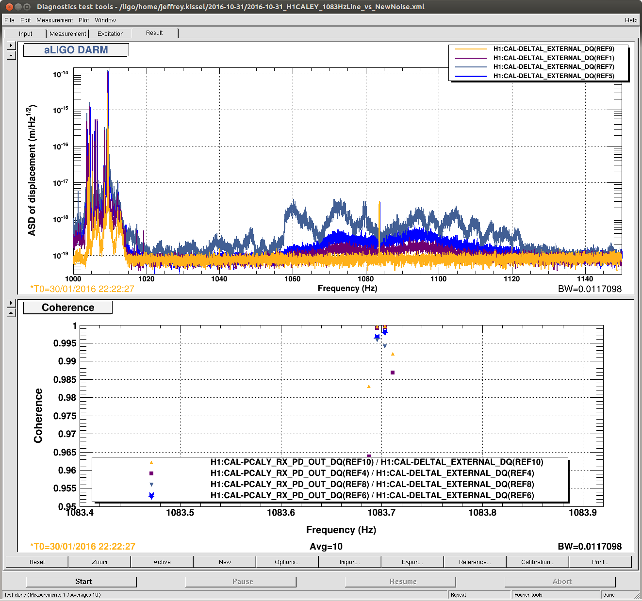
Worried that the 1083.7 Hz calibration line on PCAL EY -- the "standard candle" for the > 1kHz roaming calibration line on PCAL EX -- is being swamped by new non-stationary noise around 1.1 kHz, I took a closer look. I've compared the DARM ASD (0.01 Hz BW, 10 avgs) and coherence between PCALY RX PD and DARM at several different times:
2016-01-30 22:22:27 UTC -- Canonical O1 Reference Time, with no such new noise (Shown in YELLOW)
2016-10-31 07:00:00 UTC -- Beginning of last night's quiet, long lock stretch (Shown in PURPLE)
2016-10-31 10:00:00 UTC -- In the middle of the same long lock stretch, when the range degraded a little bit (Shown in BLUE)
2016-10-21 17:30:00 UTC -- Toward the end of the ghoulish lock stretch with high microseism, high-wind, and an 5.4 [mag] earthquake. (Shown in NAVY)
One can see that, regardless of the non-stationary noise, we can still get ample coherence between PCAL and DARM with 10 averages and a 100 [sec] FFT. Recall, this 1083 Hz line is *not* used in any of the calculations for time-dependent DARM loop parameters, so we're free to use any bandwidth and integration time we wish to get the best coherence / SNR/ uncertainty. As such, we'll just leave the line where it is.
*phew*!
Evan G., Dave B., Chris B., Thomas S.

After completely restarting the INJ_TRANS Guardian node, this finally fixed the transient injection problem as reported in LHO aLOG 31030. The interferometer was not locked, so no point in trying to recover the signal in a low-latancy analysis. This is the entry in the schedule file:
1161980000 INJECT_CBC_ACTIVE 0 1.0 /ligo/home/evan.goetz/lscrepos/Inspiral/H1/coherentbbh7_1126259455_H1.out

I observed the signal in H1:CAL-PINJX_HARDWARE_OUT, H1:CAL-PCALX_RX_PD_VOLTS_OUT, and H1:CAL-PCALX_OFS_AOM_DRIVE_MON_IN2.
Please note the following warning about "Aborting Logging" in the log file:
2016-10-31T20:12:43.18044 INJ_TRANS executing state: INJECT_CBC_ACTIVE (101)
2016-10-31T20:12:43.18068 INJ_TRANS [INJECT_CBC_ACTIVE.enter]
2016-10-31T20:12:43.18399 INJ_TRANS [INJECT_CBC_ACTIVE.main] USERMSG 0: INJECTION ACTIVE: 1161980000.000000
2016-10-31T20:12:51.05950 Aborting Logging because SIStrLog call failed -1
2016-10-31T20:13:19.57595 INJ_TRANS [INJECT_CBC_ACTIVE.main] GPS start time: 1161980000.000000
2016-10-31T20:13:19.57602 INJ_TRANS [INJECT_CBC_ACTIVE.main] Requested state: INJECT_CBC_ACTIVE
On the attached snap of the Terramon window, the second event is a largesh EQ in Middle East. The EQ distance to H1 is 1000km shorter than the distance to L1 but the computed site velocity is 1/2 at H1 versus L1. Is this one of those cases where the waves arrive first from opposite directions and so the crust encountered is different for the travelling surface waves? Interesting info I'm sure everyone wants to know. I see a similar descrepency for the G1 and V1 velocities but those waves are certainly travelling on the same direction. Maybe it is just the local site geology being taken into account? HunterG? Thanks-H
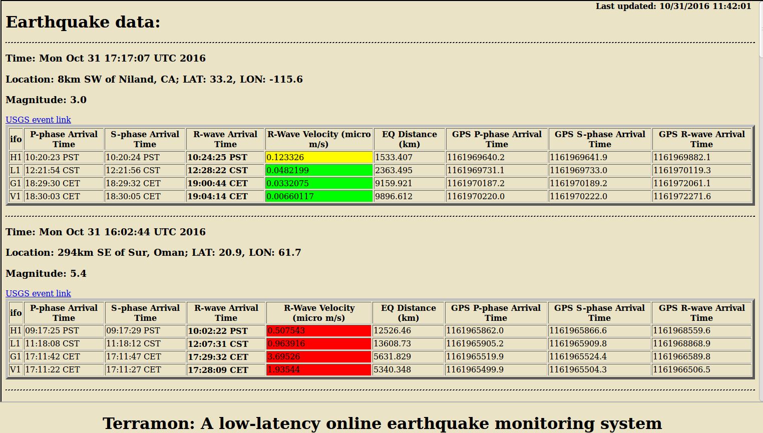
Hey Hugh!
Apologies for the late response. I'm going to paraphrase what Michael Coughlin told me in a recent discussion.
We have historically attributed the different behavior to the sites themselves rather than to any particular selection effect from LHO and LLOs location relative to most EQs. Amplitude as a function of EQ direction dependence would be interesting to look at, as we essentially fit it away by only taking distance into account. Might be a good summer project for someone.
--Hunter
Last Friday (28 Oct.) and now today (31 Oct.), I unfortunately run across this error when trying to make a hardware injection test: 2016-10-31T17:47:43.17850 INJ_TRANS JUMP: AWG_STREAM_OPEN_PREINJECT->INJECT_CBC_ACTIVE 2016-10-31T17:47:43.17898 INJ_TRANS calculating path: INJECT_CBC_ACTIVE->INJECT_SUCCESS 2016-10-31T17:47:43.17943 INJ_TRANS new target: RAMP_GAIN_TO_0 2016-10-31T17:47:43.18017 INJ_TRANS executing state: INJECT_CBC_ACTIVE (101) 2016-10-31T17:47:43.18292 INJ_TRANS [INJECT_CBC_ACTIVE.enter] 2016-10-31T17:47:43.18413 INJ_TRANS [INJECT_CBC_ACTIVE.main] USERMSG 0: INJECTION ACTIVE: 1161971300.000000 2016-10-31T17:47:43.18625 2016-10-31T17:47:43.18632 *** Break *** write on a pipe with no one to read it 2016-10-31T17:47:43.18639 awgSetChannel: awg_clnt[124][0] = NULL 2016-10-31T17:47:43.18646 Error code from awgSetChannel: -5 2016-10-31T17:47:43.22723 INJ_TRANS [INJECT_CBC_ACTIVE.main] File "/opt/rtcds/userapps/release/cal/common/guardian/INJ_TRANS.py", line 549, in main 2016-10-31T17:47:43.22726 self.hwinj.stream.send(self.hwinj.data) 2016-10-31T17:47:43.22727 2016-10-31T17:47:43.22770 INJ_TRANS [INJECT_CBC_ACTIVE.main] File "/ligo/apps/linux-x86_64/gds-2.17.9/lib/python2.7/site-packages/awg.py", line 621, in send 2016-10-31T17:47:43.22772 2016-10-31T17:47:43.22772 self.append(data, scale=scale) 2016-10-31T17:47:43.22773 INJ_TRANS [INJECT_CBC_ACTIVE.main] File "/ligo/apps/linux-x86_64/gds-2.17.9/lib/python2.7/site-packages/awg.py", line 599, in append 2016-10-31T17:47:43.22774 2016-10-31T17:47:43.22774 self.open() 2016-10-31T17:47:43.22775 + ": " + awgbase.SIStrErrorMsg(ret)) 2016-10-31T17:47:43.22775 INJ_TRANS [INJECT_CBC_ACTIVE.main] File "/ligo/apps/linux-x86_64/gds-2.17.9/lib/python2.7/site-packages/awg.py", line 584, in open 2016-10-31T17:47:43.22776 2016-10-31T17:47:43.22777 INJ_TRANS [INJECT_CBC_ACTIVE.main]can't open stream to H1:CAL-PINJX_TRANSIENT_EXC: Error setting up an awg slot for the channel 2016-10-31T17:47:43.24578 INJ_TRANS JUMP target: FAILURE_DURING_ACTIVE_INJECT 2016-10-31T17:47:43.24605 INJ_TRANS [INJECT_CBC_ACTIVE.exit] 2016-10-31T17:47:43.32248 INJ_TRANS JUMP: INJECT_CBC_ACTIVE->FAILURE_DURING_ACTIVE_INJECT 2016-10-31T17:47:43.32252 INJ_TRANS calculating path: FAILURE_DURING_ACTIVE_INJECT->INJECT_SUCCESS 2016-10-31T17:47:43.32253 INJ_TRANS executing state: FAILURE_DURING_ACTIVE_INJECT (300) 2016-10-31T17:47:43.32253 INJ_TRANS new target: WAIT_FOR_NEXT_INJECT 2016-10-31T17:47:43.32254 INJ_TRANS [FAILURE_DURING_ACTIVE_INJECT.enter] 2016-10-31T17:47:43.32780 INJ_TRANS [FAILURE_DURING_ACTIVE_INJECT.main] ezca: H1:CAL-PINJX_TRANSIENT_GAIN => 0.0 2016-10-31T17:47:45.47968 INJ_TRANS [FAILURE_DURING_ACTIVE_INJECT.main] ezca: H1:CAL-PINJX_TINJ_OUTCOME => -4 2016-10-31T17:47:45.48415 INJ_TRANS [FAILURE_DURING_ACTIVE_INJECT.main] ezca: H1:CAL-PINJX_TINJ_ENDED => 1161971282.48 2016-10-31T17:47:45.52790 INJ_TRANS [FAILURE_DURING_ACTIVE_INJECT.run] USERMSG 0: ERROR Chris Biwer suggested a simple test that I think worked: >>> import awg >>> import numpy >>> stream = awg.ArbitraryStream('H1:CAL-PINJX_TRANSIENT_EXC', 16384, 1161970100) >>> timeseries_data = numpy.zeros(10) >>> stream.send(timeseries_data) Warning, couldn't open log file Aborting Logging because SIStrLog call failed -4 Warning, couldn't open log file Chris B. and Dave Barker have been notified of this issue.
J. Kissel

Admiring the work of the SEI and ASC teams, we've just lost lock on a really impressive lock stretch in which we had ~40 mph winds, ~70th percentile microseism, and a 5.4 Mag earhtquake in the horn of Africa and survived. It would be most excellent it DetChar can compare amplitudes of ISC control signals, check out the beam rotation sensor tilt levels, the ISI platform sensor amplitudes, take a look at optical lever pitch and yaw compared with ASC signals etc.
    Start: Oct 31 2016 16:15:05  UTC
    End:               17:37-ish UTC
Winds and some ground BLRMS (showing microseism and the earthquake arrival) for this lock stretch. We survived at least one gust over 50mph before losing lock. No one changed seismic configuration during this time.
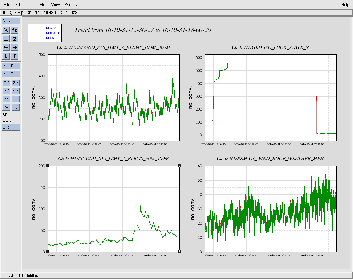
For the record, the units of the above attached trends (arranged in the same 4-panel format as the plot) are
    ([nm/s] RMS in band)        [none]


    ([nm/s] RMS in band)        [mph]

Thus,
- the earthquake band trend (H1:ISI-GND_STS_ITMY_Z_BLRMS_30M_100M) shows the 5.3 [mag] EQ peaked at 0.1 [um/s] RMS (in Z, in the corner station, between 30-100 [mHz]),
- the microseism (again in Z, in the corner station, H1:ISI-GND_STS_ITMY_Z_BLRMS_100M_300M) is averaging 0.25 [um/s] RMS between 100-300 [mHz] (which is roughly average, or 50th percentile -- see LHO aLOG 22995), and
- the wind speed (in the corner station) is beyond the 95th percentile (again, see LHO aLOG 22995) toward the end of this lock stretch, at 40-50 [mph].

Aside from Jordan Palamos' work in LHO aLOG 22995, also recall David McManus' work in LHO aLOG 27688, that -- instead of a side-by-side bar graph, shows a surface map. According to the cumulative surface map, with 50th percentile winds and 95th percentile winds, the duty cycle was ~30% in O1.

So, this lock stretch is not yet *inconsistent* with O1's duty cycle, but it sure as heck-fy looks promising.
To recover our alignment after the PSL work that happened last week, IM3 was moved pretty significantly (alog 30910). For the last week or so, it has been regularly running extremely close to the edge of the actuation range for LL and UR. The MasterOut channels are around 126,000 counts, but the front end model outputs are above 130,000. It would be great if someone from DetChar could have a look and make sure that we're not causing ourselves trouble by operating so close to the DAC edge here. Note that the VoltMon channels for these two OSEMs are totally railed, so they will not be useful for looking at - I don't know if those are a regular part of the detchar scripts.
This will reduce unnecessary HEPI slow system movement. This movement could be causing creek and maybe slow albiet minor alignment changes.
When both the ISI and HEPI Isolation loops are closed, the first step is to measure the free hanging position so the loop starts with zero DC shift. Once the loop is fully engaged, the "Target Reference Location" is ramped into the loop to put the alignment of the platform to a repeatable place. This restoration of position happens for all HEPIs and the HAM ISIs. The BSC ISIs do not restore a Target position; no evidence to show now, but we don't see large shifts or wanderings of the BSC ISI positions.
Okay, for the HEPIs, the Vertical and Horizontal Pringle modes are overconstrained dofs of the HEPI platforms--8 actuators with 6 degrees of freedom. As such these isolation loops are not DC coupled as are all the other dofs X Y Z RX RY & RZ. As such though, the restoration of a Target position into the AC coupled loop puts a large step into the loop and drives. Attached are 30 day trends showing four ITMX HEPI trips. The large step up on the horizontal Actuator drives are the restoration of the old target position of 900nm (upper right trace.) This HP measurement is literally a distortion of the platform, some taken up by the soft Actuator connection and some by actual stress in the platform. I would be most worried about yaw alignment shifts but there are none evident in the optical levers. Given the length of this trend plot though, most of the optical lever data here may be in-loop. There is probably some ASC output I could trend for that.
The bottom line is that since these are AC coupled loops and over some time, the offsets are AC'd out of the loop, why put them in in the first place. Start the loop in the free hanging location like all loops and let this AC loop slowly go where it will. We don't expect them to go much of anywhere. Just avoid the potential problems no matter how minor.
I propose all HEPI Pringle loops be removed from the Target location restoration list (Guardian chamber edits.) This has been discussed in the weekly SEI subsystem call and principals agree.
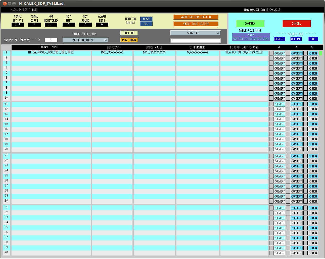
J. Kissel for S. Karki

I've moved the roaming high frequency calibration line driven by PCAL X from 1501.3 to 1001.3 Hz at Oct 31 2016 15:44:29 UTC (1161963886, 08:44:29 PDT). Note, O2 reference measurements for PCALX will be taken tomorrow, we should be sure to scale any results to those measurements.

Here's the status:
Frequency    Planned Amplitude        Planned Duration      Actual Amplitude    Start Time                 Stop Time                    Achieved Duration
(Hz)         (ct)                     (hh:mm)                   (ct)               (UTC)                    (UTC)                         (hh:mm)
---------------------------------------------------------------------------------------------------------------------------------------------------------
1001.3       35k                      02:00                   39322.0           Oct 31 2016 15:44:29 UTC
1501.3       35k                      02:00                   39322.0           Oct 24 2016 15:26:57 UTC    Oct 31 2016 15:44:29 UTC      ~week @ 25 W
2001.3       35k                      02:00                   39322.0           Oct 17 2016 21:22:03 UTC    Oct 24 2016 15:26:57 UTC      several days (at both 50W and 25 W)
2501.3       35k                      05:00                   39322.0           Oct 12 2016 03:20:41 UTC    Oct 17 2016 21:22:03 UTC      days     @ 50 W
3001.3       35k                      05:00                   39322.0           Oct 06 2016 18:39:26 UTC    Oct 12 2016 03:20:41 UTC      days     @ 50 W
3501.3       35k                      05:00                   39322.0           Jul 06 2016 18:56:13 UTC    Oct 06 2016 18:39:26 UTC      months   @ 50 W
4001.3       40k                      10:00
4301.3       40k                      10:00
4501.3       40k                      10:00
4801.3       40k                      10:00
5001.3       40k                      10:00
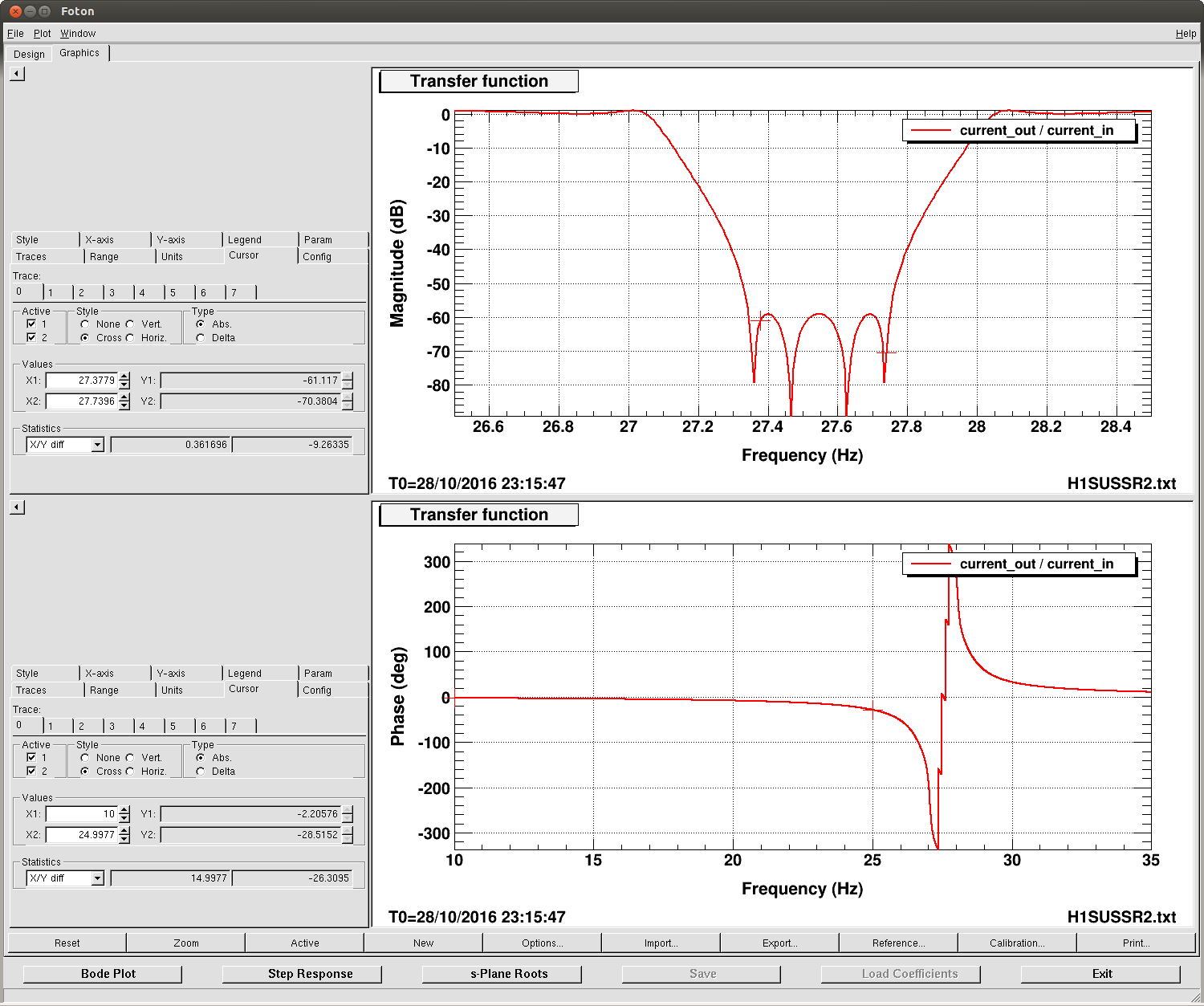
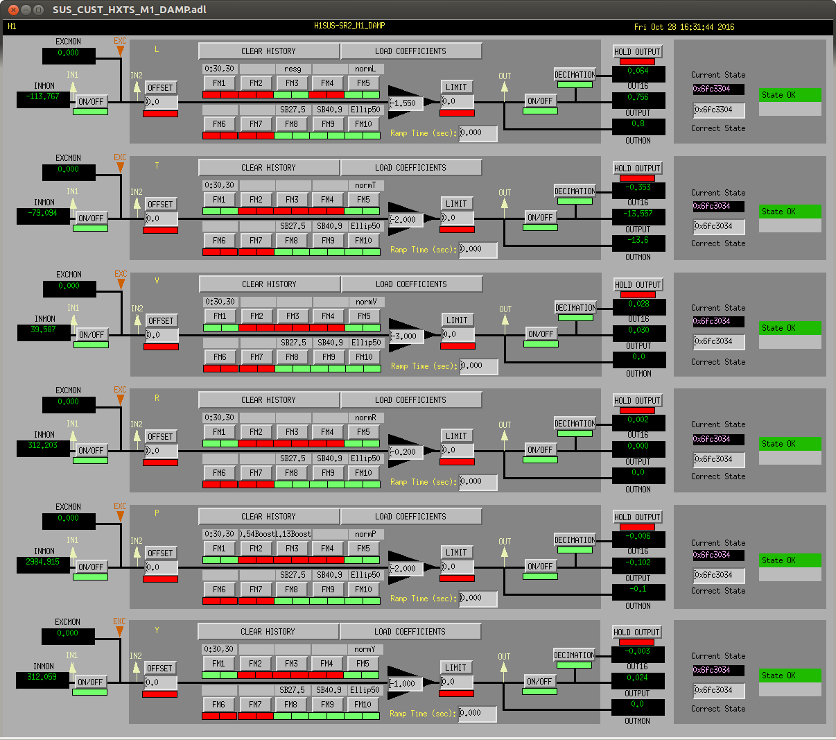
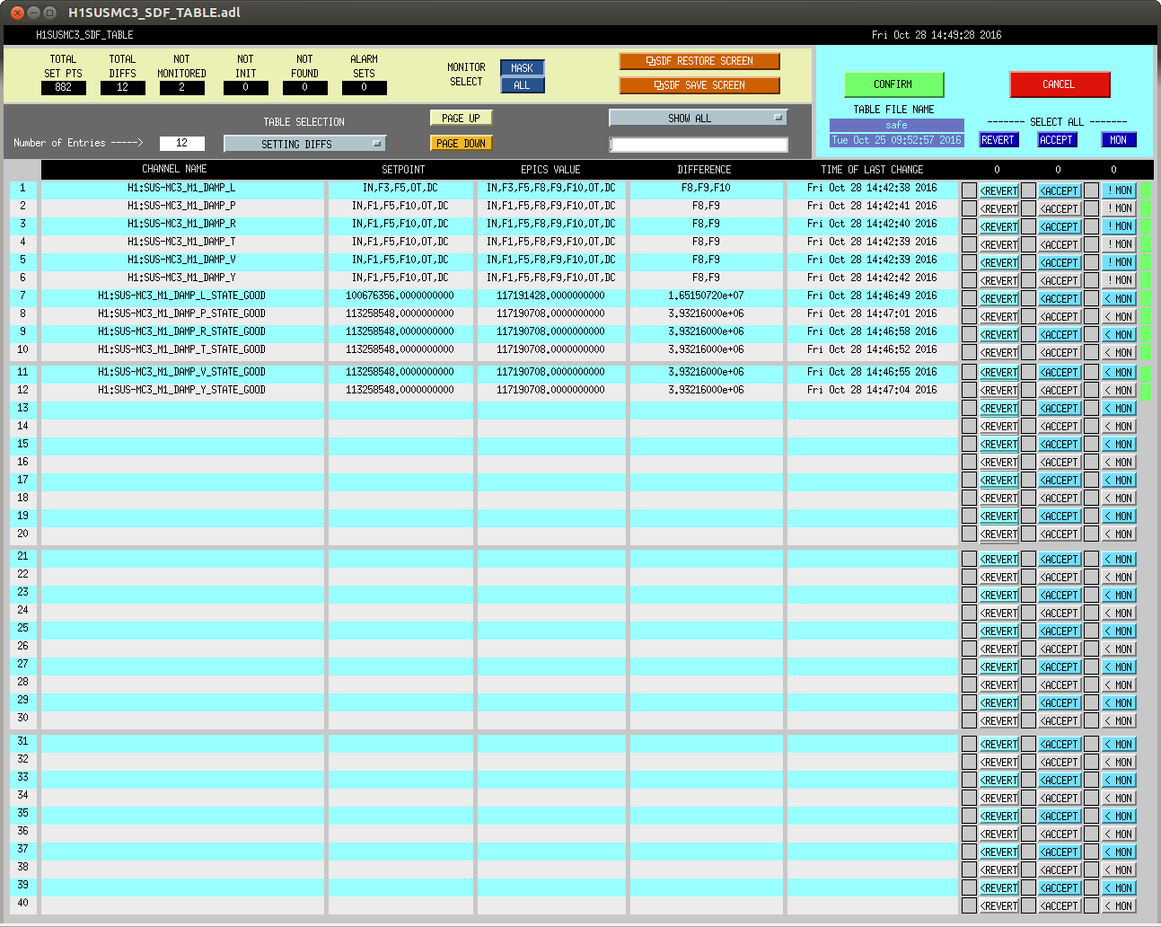
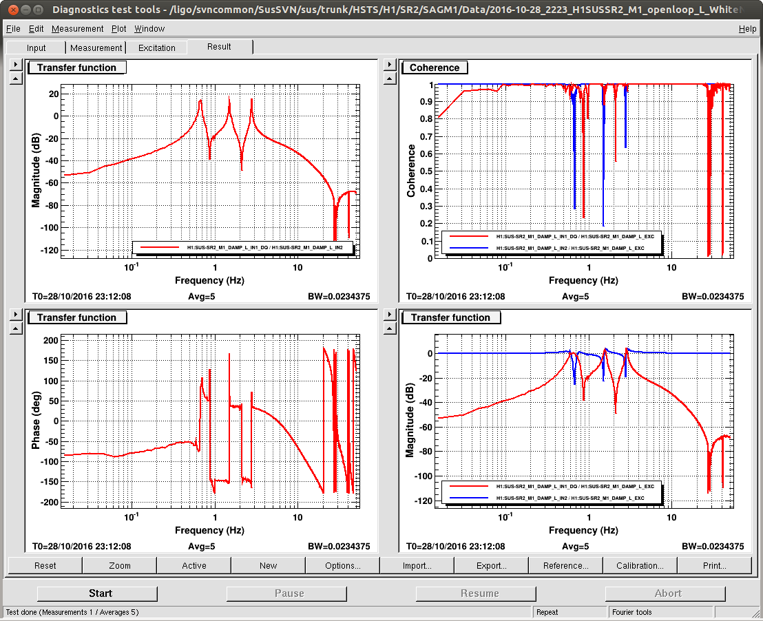
J. Kissel

With hints of improvement last night from Sheila (see LHO aLOG 30947) on reducing the most egregious ~41 Hz peak in DARM (which is known to be the HSTS roll modes, a.k.a R3), I launched a campaign of adding similar ~1 Hz wide notches to all HSTS suspensions' local damping loops (M1_DAMP) at both the highest roll mode and highest vertical modes (a.k.a V3 at ~27.5 Hz).

The filter designs are
V3 notch: FM8 "SB27.5" ellip("BandStop",4,1,60,27.05,28.05)gain(1.12202)   [Input -- Always On; Output -- Ramp; Ramp Time -- 2 sec]
R3 notch: FM9 "SB40.9" ellip("BandStop",4,1,60,40.4,41.3)gain(1.12202)     [Input -- Always On; Output -- Ramp; Ramp Time -- 2 sec]
where I've made sure that the lowest and highest frequency V3 modes (coincidentally both IMC mirrors: MC1 @ 27.38 Hz, MC2 @ 27.74 Hz) faLL within the stop band of the notch (and I've confirmed that this is true with Sheila's R3 notch design as well). Further, the V3 notch causes a phase loss of only 2.2 [deg] at 10 Hz, so it will not impact any of the damping loop's phase margins. To confirm, I've spot checked SR2's local damping open loop gain tfs just to be sure. Indeed all DOFs are still quite stable (and quite poorly tuned, as expected).

During the campaign I found that PRM, MC1, and MC3's "ellip50" standard low-pass filters were not engaged, so I engaged them.

I've greened up all ODC status lights, and then accepted all of the changes in the SDF system -- V3 filters ON, R3 filters ON, ellip50 filters ON, and Correct Damp State.

While haven't had an uber-long lock stretch since I've turned on all of these notches, I was at least able to grab 5 averages of a 5 [mHz] BW ASD and compare against the long data set from last night. The notches appear to have done their job -- a large fraction of the modes have been squashed and don't show up in DARM anymore. Success!

The SR2 damping loop open loop gain TF templates have been committed here:
/ligo/svncommon/SusSVN/sus/trunk/HSTS/H1/SR2/SAGM1/Data/
2016-10-28_2223_H1SUSSR2_M1_openloop_L_WhiteNoise.xml
2016-10-28_2223_H1SUSSR2_M1_openloop_P_WhiteNoise.xml
2016-10-28_2223_H1SUSSR2_M1_openloop_R_WhiteNoise.xml
2016-10-28_2223_H1SUSSR2_M1_openloop_T_WhiteNoise.xml
2016-10-28_2223_H1SUSSR2_M1_openloop_V_WhiteNoise.xml
2016-10-28_2223_H1SUSSR2_M1_openloop_Y_WhiteNoise.xml

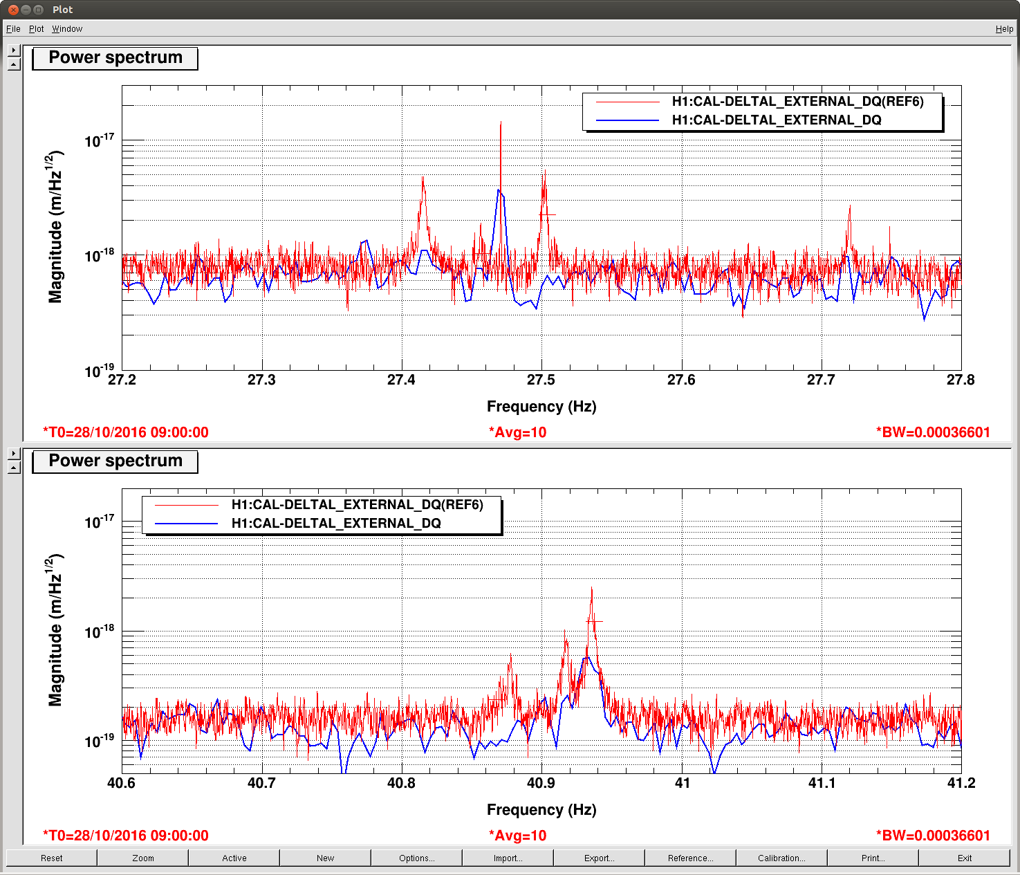
Following up with another extremely long lock stretch from over the weekend (new data starts at 2016-10-31 07:00 UTC), it looks like I've definitely killed several of the resonances, such that they don't substantially appear in the DARM noise.

However, the MC2 V3 mode @ 27.7642 Hz and what remains of the PR2 R3 mode @ 40.935 Hz are still as bad as they were before. This likely means these modes are getting excited via non-local control. The ISC control is a likely culprit for MC2, because the V3 mode is abnormally high and may be out of range of a generic notch. Further the IMC cross-over is around 15 Hz, so notching these frequencies is more difficult (i.e. there's currently no notches for the M3 stage length control of the IMC).

We'll continue to poke around looking for poorly notched loops.
