Jennie W, Madi S, Sheila D,
Summary: JAC REFL A PD and WFS A and B are well-aligned and the beam is centred on the steering mirrors, but still some sign confusion on the readout for the WFS A quadrants and the WFS B DC readout (the QPD).
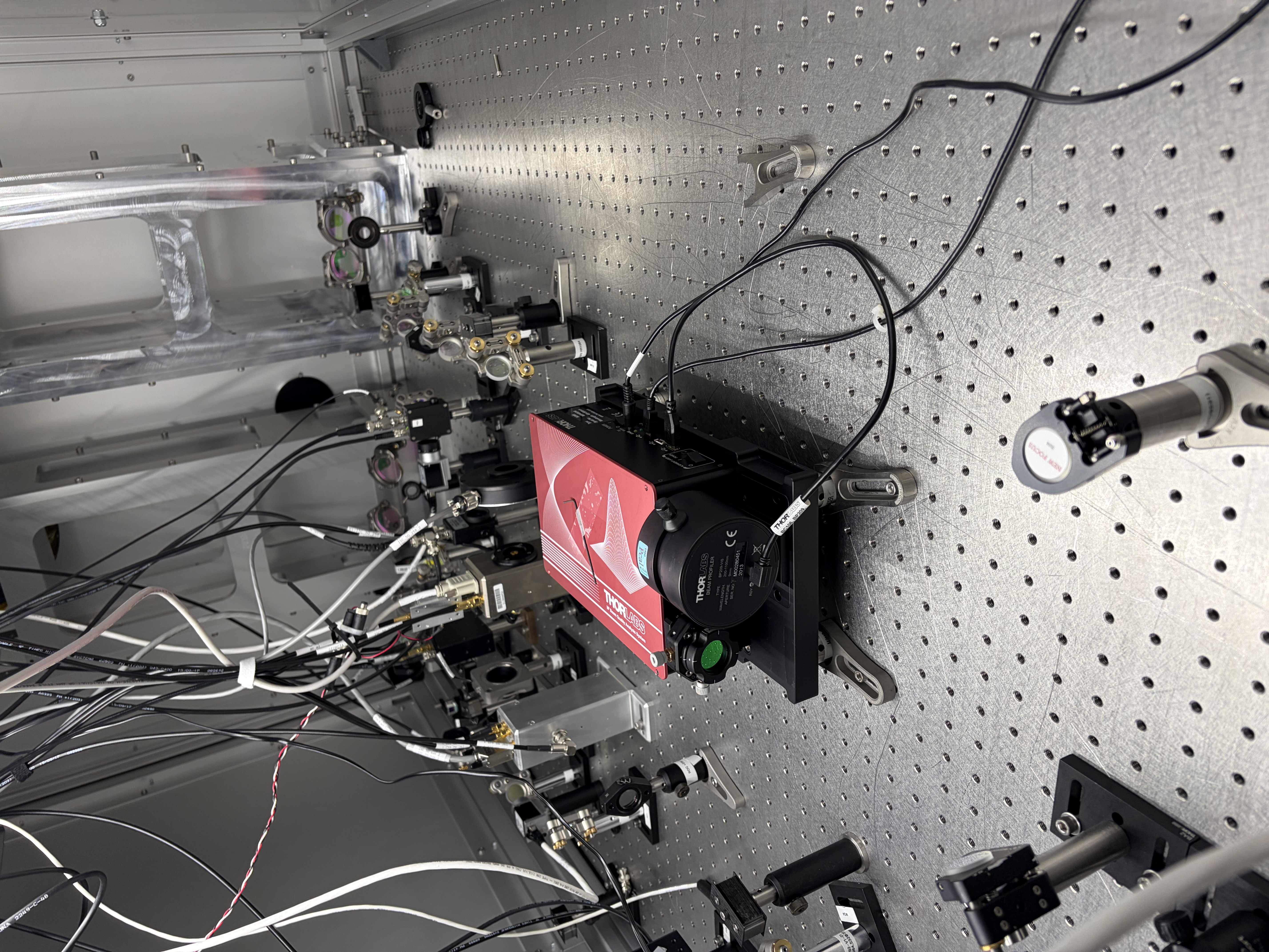
Earlier Madi and I went and re-centred the beam on the IOT1 steering mirrors JACR-BS3, BS4, M8, M9, M10. We then re-aligned the REFL PD and both WFS QPDs.
While centering we realised the degrees of freedom were switched.
After checking in the QPD input matrix for both WFS A and B, I found these were the wrong sign.
These matrix parts were copied from the IMC model and I didn't realise the IMC QPDs have a switch between pitch and yaw due to the periscopes that carry IMC REFL beam from MC1 to the in-air IOT2L.
I have switched both JAC QPD input matrixes to the values shown here.
I also checked the WFS I input matrix vales for A and B and these appear the have the correct signs for each quadrant.
Then I went to the table to do some sign checks on the QPD RF readouts to confirm these are hooked up correctly.
First I locked the JAC and then detuned it so the WFS signals are dominated by length noise. An offset of 0.4 in JAC-L_SERVO_OFFSET can be used to detune the cavity without unlocking.
Then I checked that the motion of the across the QPDs matches what we measure.
Moving anti-clockwise on pitch adustment knob for WFS A is down on QPD and on JAC-WFS_A_DC_PIT.
Moving left on QPD is down on JAC-WFS_A_DC_YAW.
QPD A seems to have the correct matrix.
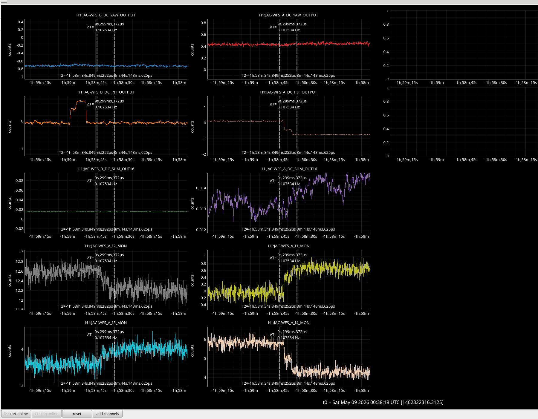
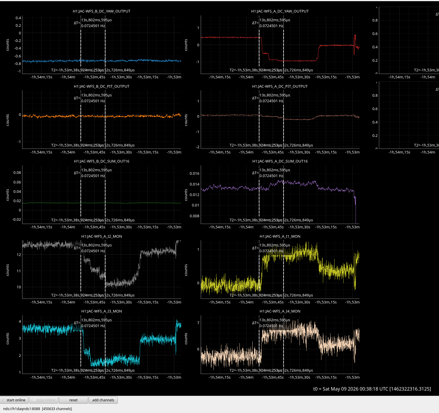
As I was doing these adjustments I looked at the four demodulated I-quadrature signals for WFS A.
Whent the beam moves down in pitch quadrant 2 and 4 go down and quadrant 1 and 3 go up - this is confusing as 1 and 3 should be diagonal from each other. See ndscope.
When the beam goes down in yaw quadrant 1 and 4 go up and quadrant 2 and 3 go down - the opposite way to what we expect from the motion on the QPD. See ndscope.
I did the same series of checks for WFS B
Moving anti-clockwise with the pico mirror pitch adjustment knob is up on the QPD itself but down on the WFS-B_DC_PIT channel, this is wrong.
Moving anti-clockwise with the pico mirror yaw adjustment knob moves right on the QPD itself and up on WFS_B_DC_YAW channel - this makes sense.
So maybe we need to change the input matrix for this or fix some wiring.
Still need to check the four demodulated I-quadrature signals for WFS B.
NB: Two months ago we started commissioning the JAC WFS and discovered that the X and Y on the A picomotor are swapped somewhere in the chain, see alog #89437. This probably needs the control wires swapped at the pico signal distribution box on the table itself but the picos are not hooked up at the moment as the controlled is shared with IOT2L which is unplugged for vent work in HAM2.


