Cao, Elli
To measure the SRC gouy phase, we need to move the BS and PR2 optics in yaw and know the angle we move them to at least 5% (but ideally more like 2%). So today we checked the calibration of these optics' alignment sliders using the ETMY baffle PDs. We have used the method which was previously used to calibrate the BS optic align sliders (alog 14321), although we have taken extra care to loacte the center of the baffle PDs, as we are particularly interested in understanding the accuracy of this measurement. Just to be clear, we are not making any changes to the alignment slider gains, we are simply measuring how good the current ones are.
Method:
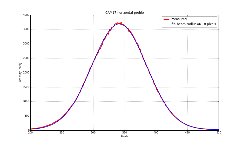
The BS was moved in pitch and yaw to direct the PSL beam onto each of the ETMY baffle PDs (PD1 and PD4). PRM, SRM, ITMs, ETMs and TMSs were misaligned to prevent flashes from other optics from corrupting the baffle PD signal. Once the PSL beam was directed onto a baffle PD, we moved the BS around and plotted BS location vs intensity. We fit gaussian profile to this plot to pinpoint the BS slider values for when the beam is centered on each of the baffle PDs. (Attached are the plots of slider value vs PD power and the fited gaussian, for the BS).
This procedure was repeated using the PR2 to direct the beam onto each baffle PD.
Results:
BS | ||
P "urad" | Y "urad" | |
ETMY PD1 | 150.7+/-0.1 | -294.1+/-0.1 |
ETMY PD4 | 186.3+/-0.1 | -329.4+/-0.1 |
Difference in optic align values when moving from PD1 to PD4 | 35.6+/-0.2 | 35.3+/-0.2 |
Multipied by 2 for angle beam moves to go from PD1 to PD2 | 71.2+/-0.5% | 70.6+/-0.5% |
We can check the calibration of these sliders by comparing to the angle the beam moves through to move from PD1 to PD4, as calulated from the geometry of the interferometer. Accordong to Jeff and Gerado (alog 14321, D1200296), the baffle PD locations are 11.329 [inches] = 0.288 [m] apart in vertical, and 11.313 [inches] = 0.287 [m] apart in horizontal. With a 3994.5m long arm (LHO aLOG 11611), and 4.986 [m] for the distance between the HR surface of the BS and the back of the ITMY CP, through the thin CP, through the ITMY to the HR surface of ITM, respectively (D0901920), that's a lever arm of 3999.5 [m]. Hence, a displacement of
BS P 0.288 [m] / 3999.5 [m] = 72.01 [urad]
BS Y 0.287 [m] / 3999.5 [m] = 71.76 [urad]
The alignment offset slider gains can therefore be corrected by
BS P 72.01 / 71.2 = 1.011 [urad/"urad"]
BS Y 71.76 /70.6 = 1.016 [urad/"urad"]
or
BS P 0.989["urad"/urad]
BS Y 0.984 ["urad"/urad]
Which means the BS calibration is pretty bloody good. Go team!
Checking the calibration of the PR2 alignment sliders can be done similarly, provided we take into account the extra distance from PR2 to PR3 to BS, and the ROC of the PR3. This looks like a job for tomorrow.
PR2 | ||
P | Y | |
ETMY PD1 | 1699+/-1 | 4475+/-1 |
ETMY PD4 | 1957+/-1 | 4180+/-1 |
Difference in optic align values when moving from PD1 to PD4 | 258+/-2 | 295+/-2 |
We broke the lock this morning to do this measurement. We have returned all optics to where they were and are leaving the interferometer in the down state (I had a shot at relocking but I've been away too long it appears :( ).
Den, Kiwamu, Evan
Tonight we again made it to low noise, although the locking procedure is still not robust enough. In the end, it seems that the sensitivity degredation is not due to a new mystery noise, but rather is a consequence of a shift in the interferometer alignment and some left-over temporary equipment.
List of changes/observations for locking is as follows:
Once we reached the low-noise state, we again saw the excess noise that has been bothering us for the past few days. We were able to partially mitigate this as follows:
The sensitivity is now 70–76 Mpc.
Finally, we looked for high-frequency frequency noise downconverting into DARM. We didn't see anything, but here is what we did:
We also made some tweaks to the ALS locking:
Attached are transfer functions of IMC jitter (sensed by the IMC WFS) into DARM, compared against the previous TFs measured in September. One can see that the pitch coupling is higher by more than a factor of 3.
Den, Evan, Sheila, Hang
We've spent some time on ASC today. First of all we added yesterday's changes to the DRMI ASC (25630) to the guardian, but used the new AS36 A phasing from early this morning. This seems to work fine.
We also measured the sensing matrix for the INP1, PR3, and CHARD in the refl WFS. For pitch, in counts/counts
CHARD | IM4 | PR3 | |
9A | 1.9 | -5.9 | 1 |
9B | 2.3 | 4.3 | 4.7 |
45A | 2 | -4.9 | -2 |
45B | 2.4 | 4.0 | -2.3 |
excitation amp | 3e3 | 100 | 200 |
demod phase | 0 | 90 | 0 |
Den set this up using the locking oscillator, the excitation amplitude and demod phases used are for future reference. For yaw:
CHARD | IM4 | PR3 | |
9A | -2.1 | 7.8 | -3.4 |
9B | -3.3 | -5.1 | -7.8 |
45A | -2.1 | 8.3 | -0.4 |
45B | -2 | -4.6 | 4.06 |
excitation amp | 3e3 | 100 | 200 |
demod phase | 0 | 90 | 0 |
Since Den noticed that the values of the sensing matrix we got for REFL45A were fluctuating (and small compared to the others), we did not use it.
The POP offsets have changed, and right now we are using small offsets in the soft loop error points.
To summarize the last few days, we had some kind of alignment problem perhaps because of a temperature swing in the lvea on tuesday. We have fixed a few things that have been longstanding oddities in our ASC system:
This seems like great progress, although we clearly have more work to do increasing gains, and getting rid of some cross couplings between loops. Most of the new settings have been accepted into SDF, and we think all of them are in guardian, which we are about to test.
In the past 2 weeks, the crew cleaned 286 meters of Y beam tube ending at HSW-01-058. The support tubes in that same section were vacuumed and capped also.
Commissioners continue ASC commissioning. It's been a bit of a windy afternoon. I did some alarm handler work.
.HIGH Alarm Levels Changed for FMCS Air Handlers
Had a few FMCS alarms this week due to warmer temps and changes to heaters. The MAJOR alarms occured when H0:FMC-CS_LVEA_REHEAT_1B_DEGF went above 100degF. John said we should bump this up to 110degF, so I went ahead and updated the burt.snap for h0fmcs.snap. I changed all the H0:FMC-*_REHEAT*_DEGF.HIGH from 100 to 110. To do this:
Now, if we get an alarm, it's more serious, and we should notify Bubba.
Updated fmcs.alhConfig File
Mainly updated the Guidance windows to show Bubba as the primary contact. Updated this file, tested, and committed to the svn per instructions, here.
I've written a python script called check_model_daq_configuration which is designed to run between the 'make' and 'make install' phases of model compilation. It reports on the DAQ changes of the new model. It can be used to verify a DAQ change is needed after the code is installed, and to check if an existing DAQ channel is changing its data rate or data type.
As an example, I have temporarily changed a H1PEMMX channel's name by adding a zero to the end of the name. The code reports:
david.barker@opsws16: check_model_daq_configuration h1pemmx
DAQ configuration is changed, processing...
Channel H1:FEC-121_ADC_OVERFLOW_ACC_0_40 will be added to the DAQ
Channel H1:FEC-121_ADC_OVERFLOW_ACC_0_4 has been removed from DAQ
Total number of DAQ changes = 2
in this example I added 384 to a 16Hz channel
david.barker@opsws16: check_model_daq_configuration h1pemmx
DAQ configuration is changed, processing...
Channel H1:FEC-121_ADC_OVERFLOW_ACC_0_4 datarate change from 16 to 16384
Total number of DAQ changes = 1
Had fairly calm skies with small winds and then were quickly overtaken by winds (below 10mph to 40+mph!) & a bit of a torrent of rain (huge puddles and gushing rain gutters) all within a span of minutes (see winds attached).
Some mentioned hail as well. This occured right around 3pm local time.
This has been running for a couple weeks, but I've been lagging in my logging. I've installed inertial isolation on HAM1 HEPI, it seems to be working okay. The first 3 attached plots HAM1's L4Cs (in X, Z and RY, other dofs are similar) from earlier today versus HAM1's performance on Feb 9th, before I installed higher ugf loops and blend filters. On each plot solid is the currnet inertial set, dashed are from before. Red and blue are the L4Cs, green ad brow are the ground STS. Z shows quite a bit of improvement up to 9 hz, with some amplification above coming from isolation loop gain peaking. X looks pretty good, but not quite as nice. Below .1hz there is quite a bit of gain peaking from the Hua sensor correction, and more gain peaking above 10hz, similar to Z. RY doesn't get much benefit below 1hz and gets some gain peaking from the blend filters, but it gets a nice suppression of ~50 at a few hz, over what the old configuration got with 2hz loops, no inertial sensors, sensor correction only on Z.
I think it's possible the blend filters could be tuned a little better, all dofs are the same blend that I stole from LLO, so some more thought could be put in there. My last attached plot is the blend being used. When I get around to it, I'll post the complementary version, but for now suffer with the raw foton display. I haven't messed with this at all, but it's possible we are being limited by IPS noise. Similar blends on the ISI are limited by CPS noise, so it seems likely.
This morning, the IFO was locked and noone was around, so I took a look at how my endstation ISI configurations affected ASC. The two configurations I looked at are:
O1 high microseism configuration, 45mhz blends, .46hz sensor correction to St1 X&Y
The current configuration, with 90mhz blends, useism sensor correction on St1 X&Y and .46hz sensor correction on St2 X,Y&Z.
The two attached plots show ASC D/C hard and soft pitch and yaw signals. The Common ASC signals are on the first plot, Differential are on the second plot. Dashed lines are the "O1" configuration, solid lines are the "current" configuration. I don't know ASC enough to say if what matters here, but the differences aren't dramatic.The main differences are where I would expect them: the current configuration does worse at the microseism, but better over 20-60mhz. The environment is not particularly difficult today, microseism is about .5 micron (90th percentile?) RMS and winds are low. It would be good to do this measurement again under different conditions (i.e. high winds, higher microseism).
RF90 phase for ASC-AS_A was totally off this morning but AS_B was good, it turns out that somehow the whitening and awhitening didn't match for AS_A (first attachment).
In the attached 2-days trend of analog whitener (ch1) and digital anti-whitener (ch2) (second attachment), the second stage whitener/awhitener was turned off by me yesterday morning and it was good, was turned back on by me later and it was good for a while, but something turned off the digital quietly after that.
I wanted to see the guardian log but it's already in the maze of cryptic file names and it's a royal pain.
Turns out that when all WFS settings were reverted back yesterday evening (so that Den/Kiwamu/Evan can continue with full lock), 90MHz settings were also reverted back, including the whitening setting.
Yesterday, I switch the HAM3 ISI to use the "HAM5" STS (now, actually in the biergarten), did an initial measurement to make sure the ISI was performing okay, then left it overnight. This morning I compared it's performance to HAM2, and I think we should switch all of the ISIs to used this seismometer. Attached 3 spectra show the GS13 spectra for X,Y and Z over a ~1 hour period overnight. In all DOF's over most frequencies, HAM3 does better than HAM2 now, where previously they had performed similarly (excepting HAM3's transient .6hz mystery line). Most important, HAM3 does much better where sensor correction gets us most of our isolation (~.1-1hz). This is an easy change, and should be totally transparent.
I can't do more than just speculate at the moment, but I wonder if HAM3's better performance of the sensor correction than HAM2 isn't because the sensor is better but because HAM3 is ~15 [m] closer than HAM2. Is HAM2 using the "HAM2" STS-A, and is it still right under HAM2? I've lost track of Hugh's STS juggling...
All corner station platforms were using the ITMY (STS2-B) sensor, but Jim has been switching the platforms over to the HAM5 (STS2-C) sensor which has been moved to the BierGarten near STS2-B.
Below are the trends from the past 26 days as I have been on holiday and then out sick for a week.
[Jenne, Sheila, Den, Hang, Keita]
We started the day by phasing the REFL WFS, both A and B, in both 9 and 45. In particular, we knew that the 45 MHz phasing was weird. Hang will post a reply with our detailed procedure.
We also reverted the AS 36 A&B demod phases to the values that Sheila had found on Sept 1 (alog 21083).
With this new phasing, we started trying to close WFS loops.
We captured the state of the ASC in a snapshot (saved in the same folder as the SDF's snap files), and then reverted everything to the down.snap file so that noise hunting work can happen tonight.
All of today's work was done in DRMI-only, since the wind was much too high to hold the arms with ALS. So, we'll have to re-visit these phasings, but hopefully they'll only be small tweaks in full lock.
We have not yet closed the loop on the new AS 90 centering loops, since we got a bit confused earlier in the day when (it turns out) there wasn't any light on the AS WFS. Keita has set gains and phases to match the current DC centering loop, so we should be able to just change the input matrix elements (same values) over to the AS 90 column.
Overall a good day, but we need to keep pushing forward.
The detailed procedrue we used to phase the REFL WFS' is summerized below:
### determining the relative phase of 4 quardrants using the length signal ###
Drive IMC_MCL_EXC with ~1000 cts at 4 Hz.
Turn on 4 Hz bandpass filters in I1-I4, Q1-Q4 filter banks
Phase s.t. the signal in each quardrant apears in I phase.
Looking at 4 I channels together to make sure no they are in phase and no sign flip.
Turn off MCL drive.
### checking the phase for alignment signals ###
Turn on resG filters in MICH, PRCL, SRCL.
Drive PR2 M3 by dithering pit or yaw, 1 at a time
Confirm I1, I2 in phase and I3, I4 opposite phase for pit; I1, I4 in phase and I2, I4 opposite phase for yaw.
Turn off PR2 drive; turn off resG in length loops; turn off bp filters in segments.
Done.
### step size for phase adjusting ###
1 deg for 9 MHz, 5 deg for 45 MHz
#########################################
Using the way above, the new phases for the REFL WFS are (in [deg])
old | new | |
A_9 | -97.5 | -74.0 |
-88.0 | -73.0 | |
-58.0 | -74.0 | |
-65.0 | -69.0 | |
A_45 | -165.0 | -115.0 |
-175.0 | -120.0 | |
-45.0 | -95.0 | |
-50.0 | -105.0 | |
B_9 | -83.0 | -83.0 |
-85.0 | -87.0 | |
-85.0 | -84.0 | |
-79.0 | -81.0 | |
B_45 | -245.0 | 0.0 |
-235.0 | 0.0 | |
245.0 | 10.0 | |
250.0 | 0.0 |
Kiwamu, Evan, Den We have continued ASC work in full lock. We concentrated on AS 36 signals since they are the most problematic. In the past we had to control SRM and BS using a combination of A and B, I and Q signals and switch them at different states. Tonight we have phased AS_36 A WFS in full lock and used only Q -> BS and I -> SRM signals during the whole lock acquisition sequence. This WFS is phased such that BS is in Q and SRM signal is equally split between I and Q. We did the similar phasing with AS_36 B WFS, but this diode has an offset and does not maximize the power. We have also noticed that phase of this WFS changes by 45 degrees when we increase the power. For these reasons we do not use it during the lock acquisition. We also noticed that when interferometer reaches 0 CARM offset, power recycling gain is around 33 and PRC WFS switch sign. We have updated the reference for ITMY camera servo in the initial alignment such that interferometer locks with high power recycling gain. We have also witnessed several lock losses in the state when DARM WFS are engaged and DARM is switched to RF from ALS. There is a large peak at 9Hz in the DARM loop with saturates the ESD driver. We should look more carefully into this issue.
J. Kissel, J. Warner Excited to use the buried STS (see LHO aLOG 25574), Jim had switched over to using the recently-moved-to-20 [m]-from-the-building STS for sensor correction (coupled with some other new configuration changes he's trying out; see LHO aLOG 25623). He was getting poor results when comparing internal vs external sensor correction use, so I've compared the times yesterday when we had great coherence at 10 [m] and 0-5 mph winds against today, when the STS is at 20 [m] away and there are consistent 25-30 mph winds. The message: both the internal and external ASDs, in X, Y, and Z, are comparable in amplitude and yet incoherent at this location and these 25-30 mph wind speeds. That means the buried STS is not so promising for sensor correction use at this level of wind. One can compare this to results originally presented by Robert at the 40 [m] location in ~15 mph winds; see LHO aLOG 19210. You'll notice that in both of these data sets, the contrast in amplitude difference between windy and not windy is "better" in the X DOF (perpendicular to the arm) than in the Y DOF (parallel with the arm; what we're trying to improve). We shall continue to take a smattering of data points to gather statistics at all wind speeds in this location. For the impatient and saddened -- recall that we have or will employ three different methods to attack wind at EY: (1) This buried, external STS [in the testing phase now] (2) A new BRS [scheduled for delivery in mid-March] (3) A wind screen system [working on getting funding] We're trying all three just in case one actually works. Let's hope one does!
J. Kissel More data on comparing the external, buried seismometer: - 20 [m] from the building, at 15-20 [mph] - 20 [m] from the building, at 5-10 [mph] - 20 [m] from the building, at 0-5 [mph] all of which are compared against the 0-5 [mph] data while the STS was 10 [m] away from the building. Conclusion -- there's really no substantial difference between the signal in these STSs at any wind speed between 0 to 30 [mph]. Bummer. Also note that the coherence for the no wind data at both 10 [m] and 20 [m] locations shows that the external instrument is behaving just as well after Robert moved it from 10 to 20 [m]. Perhaps we should move back to the 40 [m] location? That's where we'd seen the most dramatic results. Recall, the distance from the building is a balance between decoupling from building tilt (better further away) and frequency band where coherent (better closer to the building). At 40 [m] we were worried that we didn't get coherence (under no-wind conditions) out past ~0.5 [Hz]. But we'd only need coherence out to that high a frequency if we stick with the current 0.5 [Hz] narrow-band sensor correction; we don't have to -- we can explore moving to a lower frequency, broad-band sensor correction and re-allocate the feedback blend filters if need be. The message -- we need to do more work if we want this external STS to do us any good.