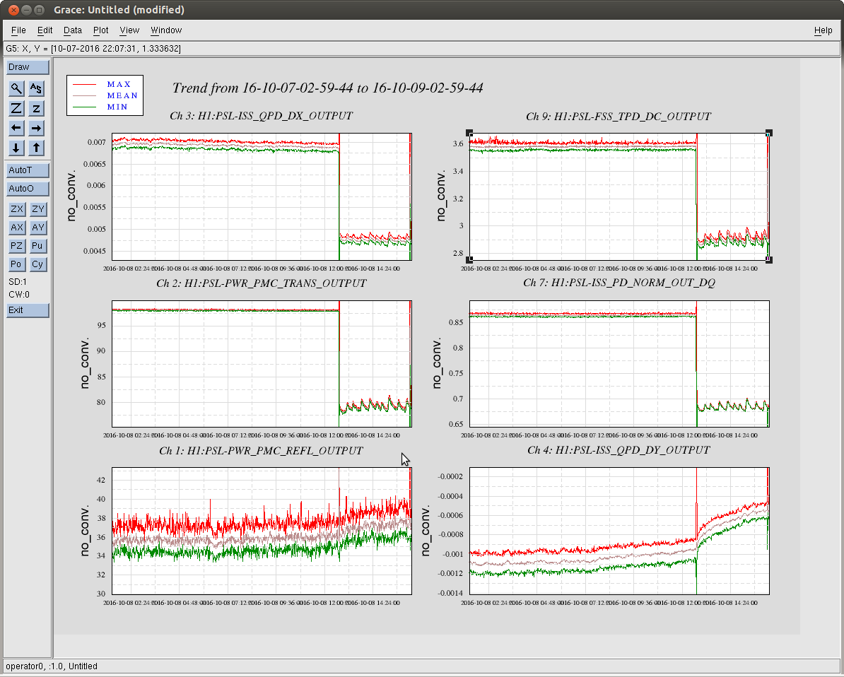
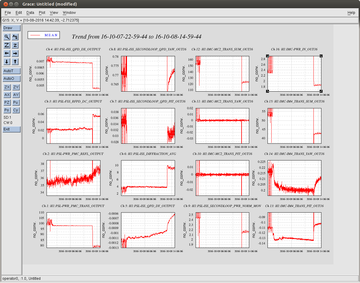
Start of shift: Sitting at DRMI_LOCKED. SRC1 Pitch and Yaw are not converging. EX constantly saturating. Diag message that PSL_ISS diffracted power is high (around 9%).
23:56 UTC H1IOPASC0 has its TIM bit red. Diag Reset cleared it.
00:01 UTC Cleared history for H1ASC-SRC1_P filter to see if it would help SRC1 Pitch converge. It did not.
00:06 UTC Stepped to DRMI_ASC_OFFLOAD. SRC1 Pitch and Yaw converged. EX still saturating.
00:09 UTC Stepped to PREP_TR_CARM. EX still saturating. ISS second loop is on.
00:13 UTC Stepped to CARM_ON_TR. EX still saturating.
00:14 UTC Stepped to REDUCE_CARM_OFFSET. EX still saturating.
00:15 UTC Stepped to SWITCH_TO_QPDS. EX still saturating. AS Air looks unstable.
00:17 UTC Stepped to RF_DARM. EX no longer saturating.
00:24 UTC Stepped to DHARD_WFS.
00:27 UTC Stepped to REDUCE_CARM_OFFSET more.
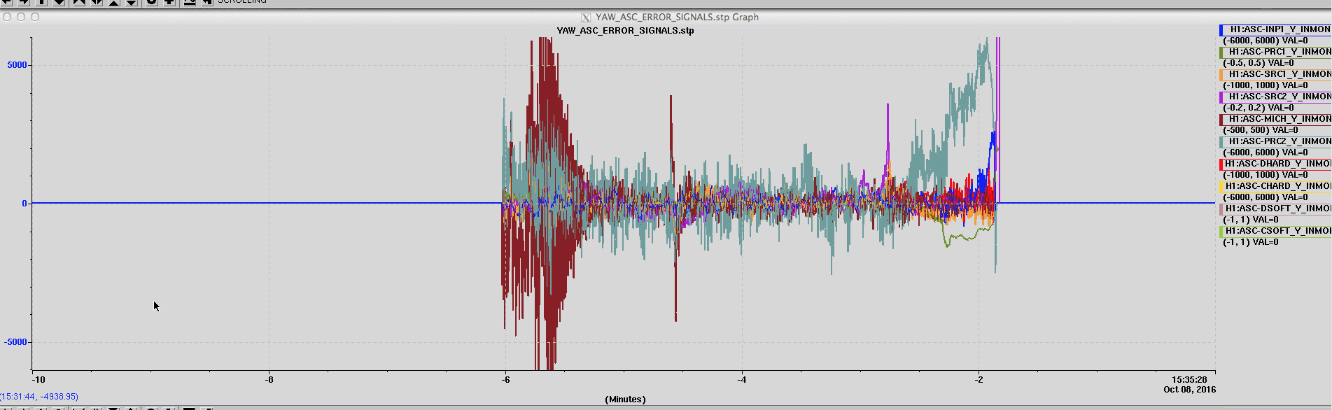
00:30 UTC Stepped to CARM_15PM. PRC2 YAW error signal stepped up.
00:34 UTC Stepped to CARM_10PM. PRC2 YAW error signal stepped up.
00:38 UTC Stepped to CARM_5PM. Almost immediately lost lock.
00:40 UTC Starting initial alignment.
00:47 UTC Video 5 images frozen. Power cycled.
Trouble locking Y arm on green. Loses lock when WFS engage. Set to LOCKED_NO_SLOW_NO_WFS and it remains fairly stable around .5. Brought Y arm to around 0.8 by adjusting ETMY, TMSY and ITMY at LOCKED_NO_SLOW_NO_WFS. Cleared WFS history. Lost the lock on Y. Put ITMY and TMSY back to original values. This time able to lock just by adjusting ETMY. It remained locked and the power increased when I changed the state back to INITIAL_ALIGNMENT.
02:16 UTC Video 4 striptool jittery. Power cycled.
02:31 UTC Initial alignment done.
02:57 UTC Stopping at CARM_10PM to try and diagnose.
03:12 UTC Lost lock sitting at CARM_10PM some time after setting the following in guardian by hand:
ezca.switch('LSC-REFLBIAS', 'FM2', 'ON')
ezca['LSC-TR_CARM_TRAMP'] = 5
ezca['LSC-PD_DOF_MTRX_TRAMP'] = 5
03:23 UTC Back to CARM_10PM. Will wait to see how stable this is.