David McManus, Jenne Driggers, Conor Mow-Lowry
This is a late post for work that was done during the week after the 4th of July.
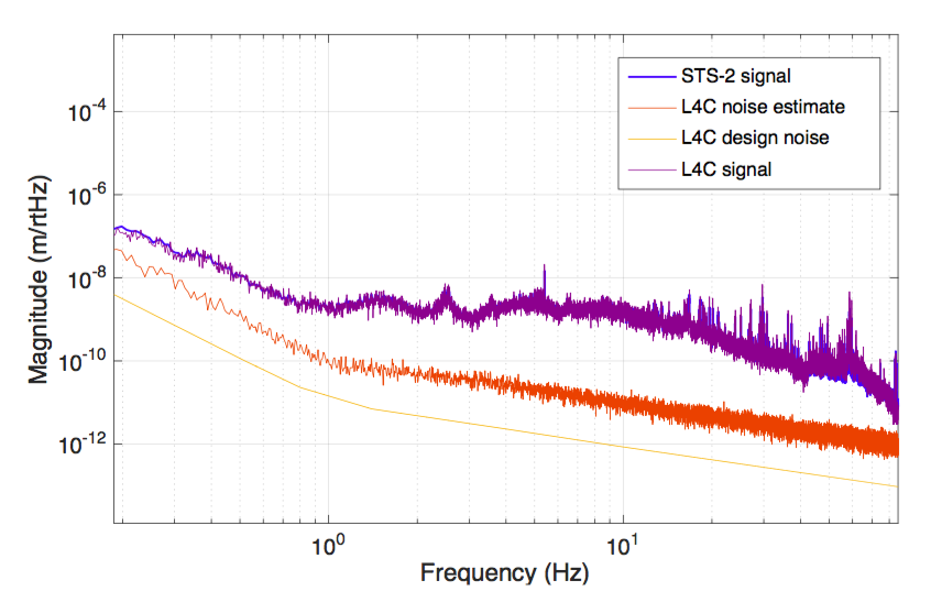
While the L4Cs were being huddled next to the STS-2, I used the mccs2 script to do a coherent subtraction of the signal from each L4C to estimate the noise floor. I plotted this against the L4C design sensor noise for comparison (taken from SEI_sensor_noise.m). We found that the noise floor estimate was still roughly an order of magnitude above the sensor noise floor. We determined that because the signal from our L4Cs is currently quite weak, we are not limited by sensor noise currently and instead are limited by some form of electronics noise (probably ADC noise). We are looking to implement some additional amplification in the L4C electronics prior to the ADC so that our SNR is improved to the sensor noise level.