corey.gray@LIGO.ORG - posted 12:24, Sunday 02 October 2016 - last comment - 12:52, Sunday 02 October 2016(30154)
12:16pm: 15min at NLN, Then PSL Trips.
15min at NLN, here are notes on DARM:
- Broadband 15-80Hz
- Big peak just below 300Hz
- Violin & harmonics (~500Hz was under 10^-15, so did not address)
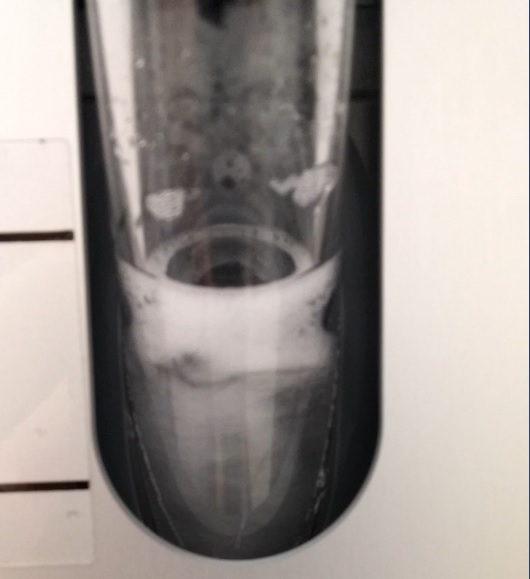
- PSL Trips at 12:16pm. Crystal Chiller cork was popped. Puddle on the floor.
- Calling Jason.
Completed Recovery in ~30min with Jason on the phone. Back to locking at 12:42pm.
NOTE: LRA, stands for Long Range Actuator.