cheryl.vorvick@LIGO.ORG - posted 13:23, Friday 30 September 2016 (30106)
IM1-4 alignment slider gains corrected -
IM alignment slider gains were reversed, and set the urad / slider count to 0.045.
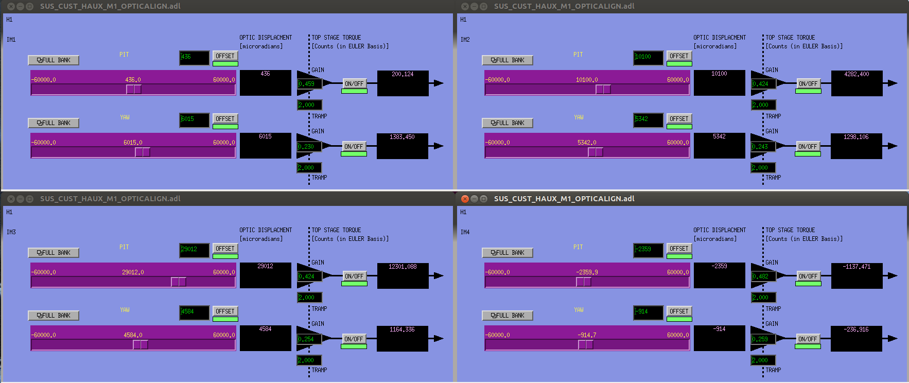
I've corrected the alignment slider gains for all IMs, and used measured values for each optic such that the urad / slider count is 0.05.
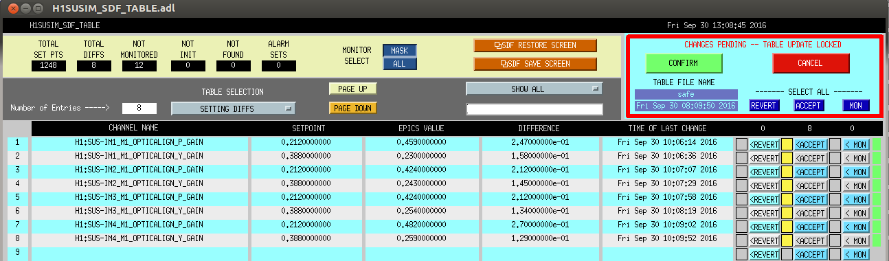
I've attached a snapshot of the new gains, and a snapshot of SDF before I acepted the new gains.
With the gain change, the slider values also change, so any burt restore prior to 30 September 2016 at 20:01UTC (13:01PT) will fail to return the IMs to their correct alignment slider values.
Images attached to this report