betsy.weaver@LIGO.ORG - posted 13:36, Friday 14 October 2016 (30540)
Signs of wind at LHO
You know it's windy when...
Images attached to this report
You know it's windy when...
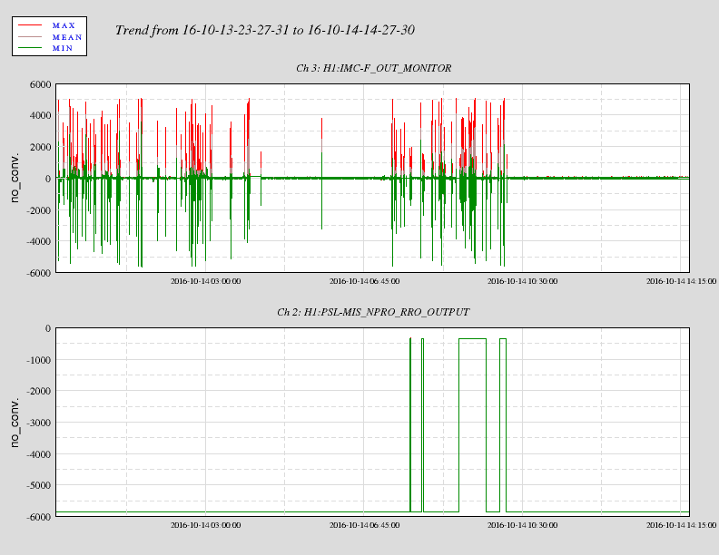
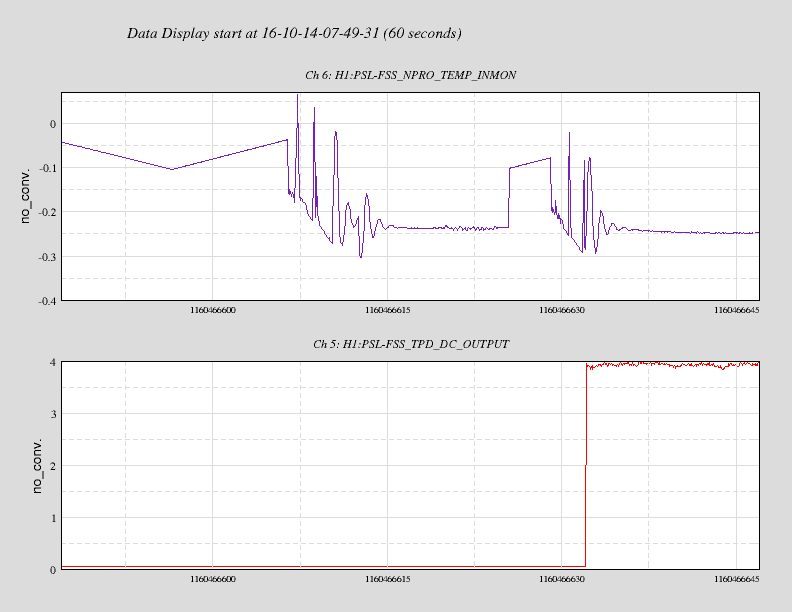
IMC_F.png shows the 4 occasions from last night when the noise eater oscillated. Anecdotally this tends to happen whenever
the IMC is trying to lock. My conjecture is that rapid transients in the FAST actuator cause larger than normal changes in
the stress-induced refractive index change in the NPRO crystal, which in turn steers the beam out of the crystal a little
differently. Since the photodiode used for the noise eater is relatively small, the beam could steer off the photodiode.
The reduction in photodiode signal then causes the noise eater to oscillate. This does not happen all the time however and
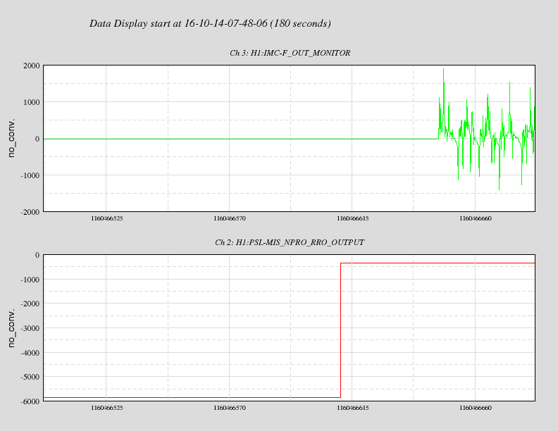
I cannot explain why. Zoomed_IMC_F.png shows that the IMC was not trying to lock at the time.
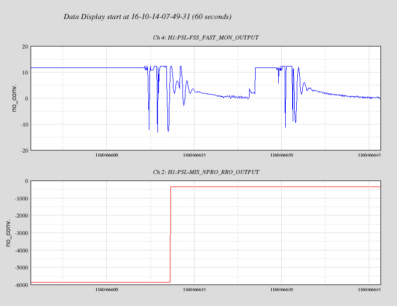
Looking at the first time the noise eater misbehaved. FAST_v_NoiseEater.png indicates that the noise eater oscillation
coincides with the third rapid increase in the FAST actuator output. The long stretch where the FAST actuator is pegged at
~11.7V indicates that the FSS was not locked at the time. SLOW_v_RCTPD.png shows that the FSS did not acquire lock at this
time but acquired lock during the second burst group of activity. Of note is Kiwamu's observation that the FSS acquired lock
at a point outside the range where the SLOW actuator is limited to in software +/- 0.1V. The FSS acquired with a SLOW
voltage of ~-0.25V. The delay in settling down is the time taken for the so-called "temp loop" to be activated, presumably
by the autolocker. Why it acquired outside this range might be due to the noise eater oscillating.
Perhaps since the autolocker did not acquire on two flashes through the reference cavity, Travis disabled the autolocker
and began the hunt for the fringe manually. Not realising that ALS likes having the SLOW voltage between -0.1V and +0.1V,
the crystal temperature kept being adjusted until a fringe was found. The next fringe was found outside this range and the
FSS acquired at -0.25V, at which point the autolocker was re-engaged.
State of H1: in Initial Alignment, struggling to lock arms in green, have only had breif locks of X arm in IR
Details:
Site Activities:
Both BRS seem to be working fine to me, I don't see anything wrong with BRS-Y.
AS of 19:58UTC (12:58PT):
BRSY is rung up - see attached
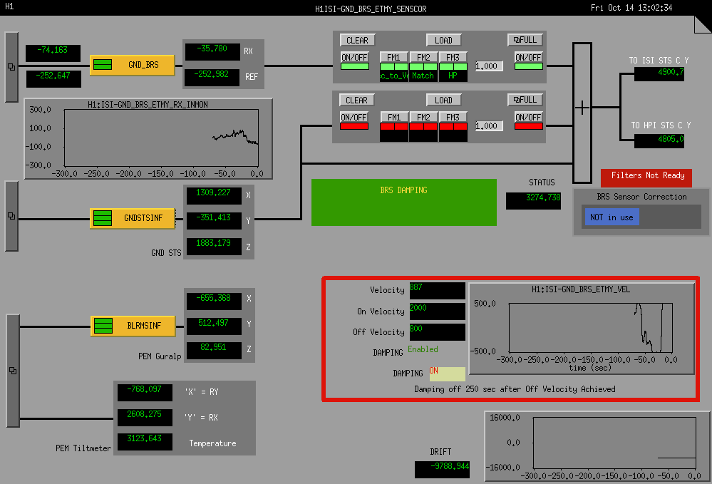
Sorry, the terminology related to BRS is a little confusing, even to me. The large velocity signal is actually caused by the large ground motion and is not a fault of the sensor. The damping will turn ON occasionally but the sensor output should still be useable. I would suggest using the BRS under these conditions.
If you want to prevent the damping from turning ON in these very high winds, the ON/OFF VELOCITY can be set higher temporarily. I think the commands are -
CAPUT H1:ISI-GND_BRS_ETMY_HIGHTHRESHOLD 5000
CAPUT H1:ISI-GND_BRS_ETMY_LOWTHRESHOLD 2000
Or you can disable the damping with:
caput H1:ISI-GND_BRS_ETMY_USER Off
Old : H1:ISI-GND_BRS_ETMY_USER On
New : H1:ISI-GND_BRS_ETMY_USER Off
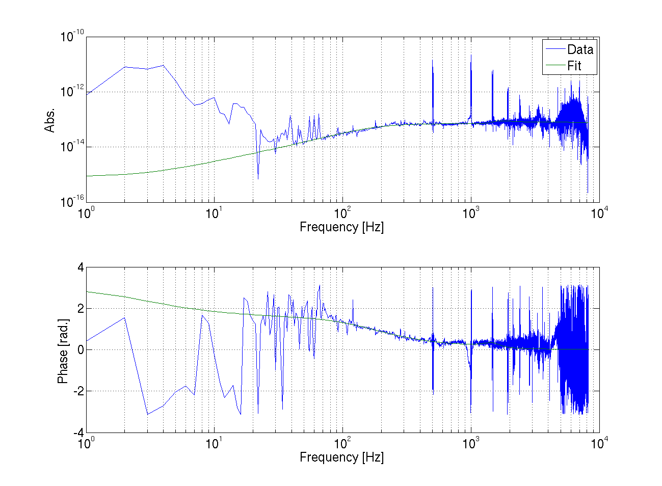
Summary:
The hardware injection inverse actuation filter has the correct amplitude and sign. This is tested using a known sinusoidal waveform and comparing the Pcal RXPD readback with the input to the inverse actuation filter. See attached figure.

Details:
Similar to my investigation of the sign of the inverse actuation filter (LHO aLOG 29072), I injected a 100 Hz signal, 1e-23 in strain amplitude, 0 phase using awgstream into H1:CAL-PINJX_TRANSIENT_EXC.

To verify the injection has the right amplitude and sign, I read out H1:CAL-PINJX_TRANSIENT_IN2 and H1:CAL-PCALX_RX_PD_OUT_DQ. The time-series data for both channels is bandpassed with a filter centered around 100 Hz. In this measurement, I did not turn on the [:1,1] filter (FM7) for the PCAL readback channel. Instead, I scaled the readback signal by -1e-4 (=-100^2). Also, I had to make an offset since there is a DC component to the Pcal signal. The TRANSIENT_IN2 has its time-series scaled by 4000 to convert between strain and meters.

The attached figure shows that the amplitude is nearly spot on, the sign is correct, and the known phase offset (~240 usec) is understood from the inverse actuation filter for the TRANSIENT injection path.

Thus, the inverse actuation filter for hardware injections is correct in amplitude and sign.
In case you need to retune the filter used for subtracting the HPO jitter (DBB QPD) from DARM, here are the steps
Notes:
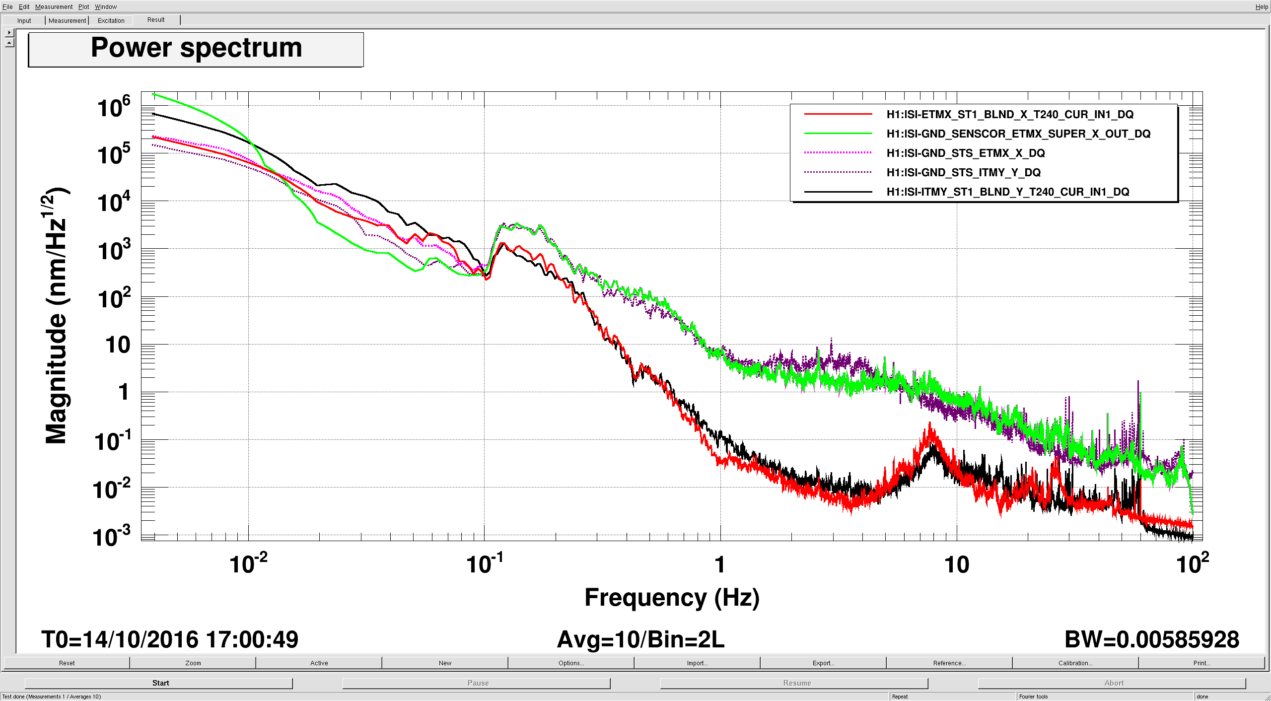
Last week KrishnaV and I found that there was a high pass filter in the tilt subtracted sensor correction path that was limiting the endstation ISI performance at the microseism. ConorM-L suggest we try just turning these filters off, as the sensor correction filter is already rolled off pretty well at 8mhz. Cheryl had the endstation sensor correction turned off for a while this morning so I took the opportunity to try this out. So far it seems to be running okay. Attached plot is the EX ISI and ITMY for comparison. Green and pink are the EX ground supersensor and STS, red is the ST1 T240. Black is the ITMY STS, purple is the ITMY ST1 T240. Before the ETMs were getting very little suppression at .1-.2 hz, and now both ETMs are generally doing as well as the corner ISIs. We'll keep an eye on this for the time being, but I think we should run like this.
J. Oberling, B. Weaver
I checked on the TCS chiller this morning and added 350mL of water to bring the level from 5.0 to 8.9. I then noticed that the mesh filter seemed to by pushing up out of the reservoir by a good bit. I reseated the filter and noticed the level had dropped to 6.3. There was still 50mL of water in the cup, so I added that to the chiller and observed the mesh filter. Sure enough, the filter puffed up. There is a large air gap between the top of the water in the reservoir and the spot that the filter seats into. What I think is happening is when we fill the chiller, that air between the water and the filter has no where to escape quickly (probably due to the amount of water moving through the filter). This creates an air bubble between the water and the filter that then influences the fill reading on the front of the chiller (hence why the reading went down when I simply reseated the filter). I have a suspicion that the chiller has not been losing water, we just haven't added enough since the system flush to completely fill it, and when we do top it off we're creating an air bubble that influences the fill level reading. We then think we've topped the chiller off when in actuality we haven't; as that air bubble slowly works its way out the level reading "drops," thereby making us think we're losing water.
I ran this by Betsy and found she was starting to suspect something similar. We went out and removed the mesh filter and then topped the chiller off, then replaced the filter. It took 600mL of water to move the indicator from 6.3 to 8.3, which is much less than we've seen in the past; if you look at the log on top of the chiller it can be seen that there are instances where we fill w/ 250mL of water and move the indicator from 5.0 to ~9.0, which is much less than the 600mL is took to go from 6.3 to 8.3. This suggests that what I wrote above is correct, we haven't been fully topping off the chiller but have been fooled into thinking we have by an air bubble of our own creation influencing the reading of the chiller fill level. One of us will check the chiller at the end of the day to check the chiller water level and see if we still need to add water (water has been added every morning and evening for every day this week).
Total water added this morning was 1000mL, and this moved the indicator from 5.0 to 8.3.
At 2:30pm PDT the water level in the TCSy CO2 chiller was reading between 7.9 and 8.0. This is a much slower decline in water level then we have been seeing this week.
Checked water tonight. Level is still up; did not add any.
I copied Gabriele's JITTERFF MEDM screen, replaced H1 with $(IFO), and saved it as $(userapps)/lsc/common/medm/LSC_CUST_JITTERFF.adl.
I added a link to that screen in the LSC overview.
9:30am local

13 sec. to overfill with 1/2 turn open on bypass LLCV. Note LLCV is still set to 16% open. Exhaust piping is completely defrosted. Left bypass exhaust valve open. Next fill due Monday.
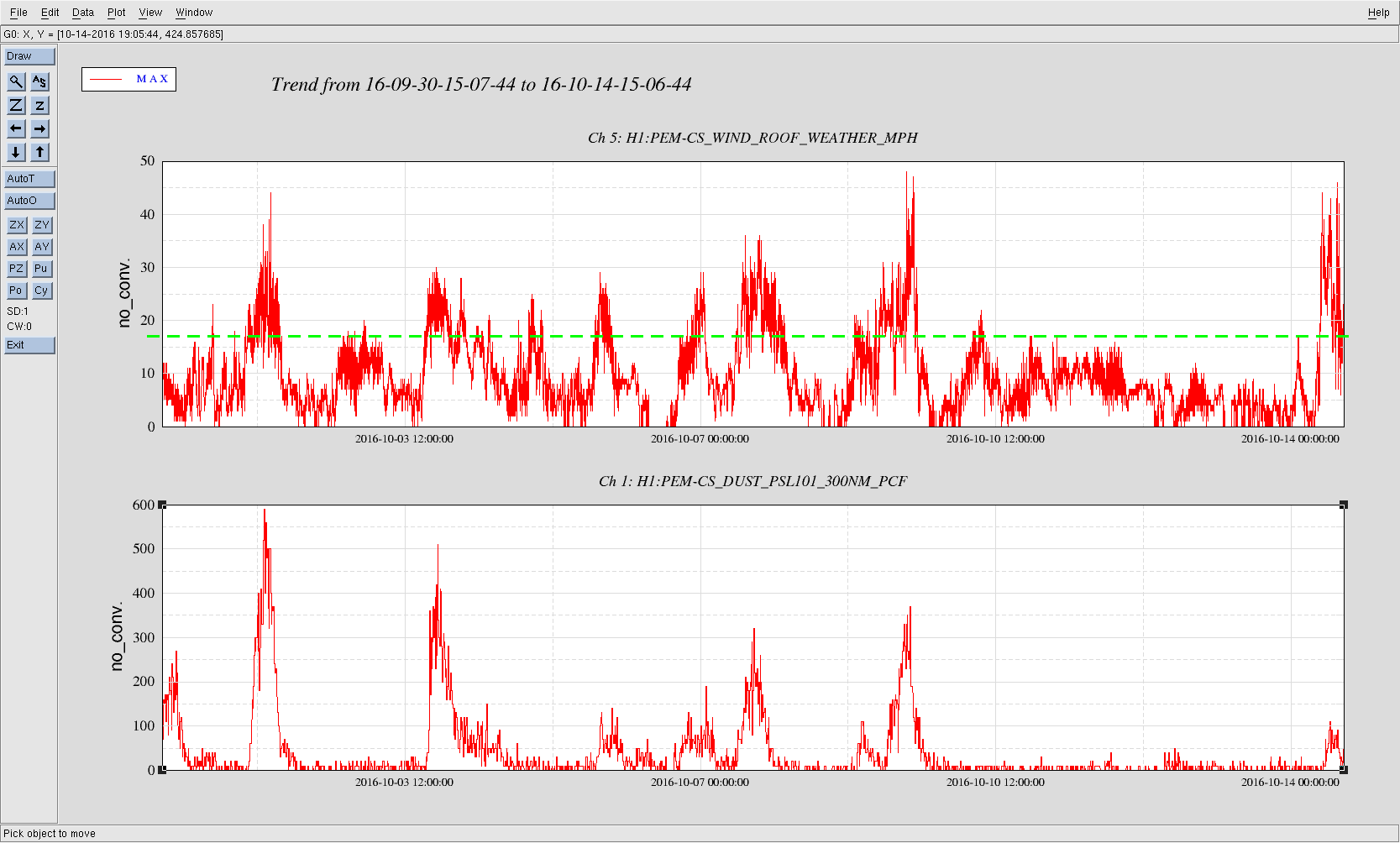
14 day plot, upper plot is corner station winds, lower plot is from the PSL, and at about 17mph the peaks in wind match peaks in the PSL dust monitor.
TITLE: 10/14 Owl Shift: 07:00-15:00 UTC (00:00-08:00 PST), all times posted in UTC
STATE of H1: Commissioning
INCOMING OPERATOR: Travis
SHIFT SUMMARY: Very windy (gusts to over 60mph) since near the beginning of my shift with high microseism (~1 um/s). Not great conditions for locking regardless of other issues we ran into. Several dust alarms in the PSL and end stations.
LOG:
9:50 DIAG_MAIN notification that the Noise Eater was out of range. Went to LVEA and reset Noise Eater. Seemed to fix the issue
10:05 Another notification that Noise Eater is out of range. Also, both ALS nodes went into fault with the same 'Beat note strengh' error (typo is in Guardian, not my log) that we saw earlier when Kiwamu found the FSS locked on the wrong fringe, aLog 30524. I again went to the LVEA and reset the Noise Eater, then attempted to toggle the Autolock off/on per Kiwamu's aLog. This did not fix the FSS issue. I don't know what else to do here.
10:23 Put Guardian into DOWN. WIll require further investigation by PSL crew/commissioners before locking will happen.
Kiwamu, Terra
One thought for tracking PI mode frequency drift over a lock stretch (as seen here) is to utilize the drumhead modes: these are reliable in amplitude/presence and by monitoring their freq drift we could predictively change PI filters, etc. to handle drifting of higher modes.
Eigenfrequencies of the test masses have nominally been defined as proportional to square root of Young's modulus: f ~ E1/2, where E := Young's modulus. The Young's modulus for fused silica has some temperature dependence ( measured to be (dE/dT)/E = 1.52e-4 / K ); as temperature increases, Young's modulus increases, so the mode frequency increases over a lock stretch. In this simple case we would expect all modes in a given test mass to have the same relative drift. Instead we see that del_f has mode dependence as well, i.e. the ~ 15007 Hz differential drumhead mode always drifts more than the ~ 8160 Hz drumhead mode of the same optic (relative to their frequency). I suspect this is due to different modes having more or less torsional versus longitudinal motion and so frequency dependence has both E (Young's) and G (shear) dependence. Peter also suggested nonuniformity of temperature in the test mass volume (as different modal motions interact with certain parts of that volume differently). To this end we define, for an arbitary mode m:
fm = g(T) , where g is some mode-specific temperature dependent function involving E,G
==> fm + del_fm ~= g0 + g1del_T + . . .
==> del_fm / fm = g1del_T / g0 = A * del_T
Similarly, for another mode n: fn + del_fm ~= h0 + h1del_T ==> del_fn / fn = B * del_T where h is some function with some different temp dependence
Then the ratio of the change of frequency over frequency of those specific modes is constant:
(del_fm/fm) / (del_fn/fn) = A / B = constant
I've quickly looked at three longer recent locks, specifically at change of drumhead modes compared to change of 15007 Hz modes of the ETMS. ETMY seems to agree on a constant while ETMX a bit wandery . I'll look more systematically tomorrow to see if I can narrow it up.
ETMY (del_Drumhead / Drumhead) / (del_15007 / 15007) = 1.38, 1.31, 1.31 | ETMX (del_Drumhead / Drumhead) / (del_15007 / 15007) = 1.29, 1.45, 2.45
See attached screenshots of OpLev trends.
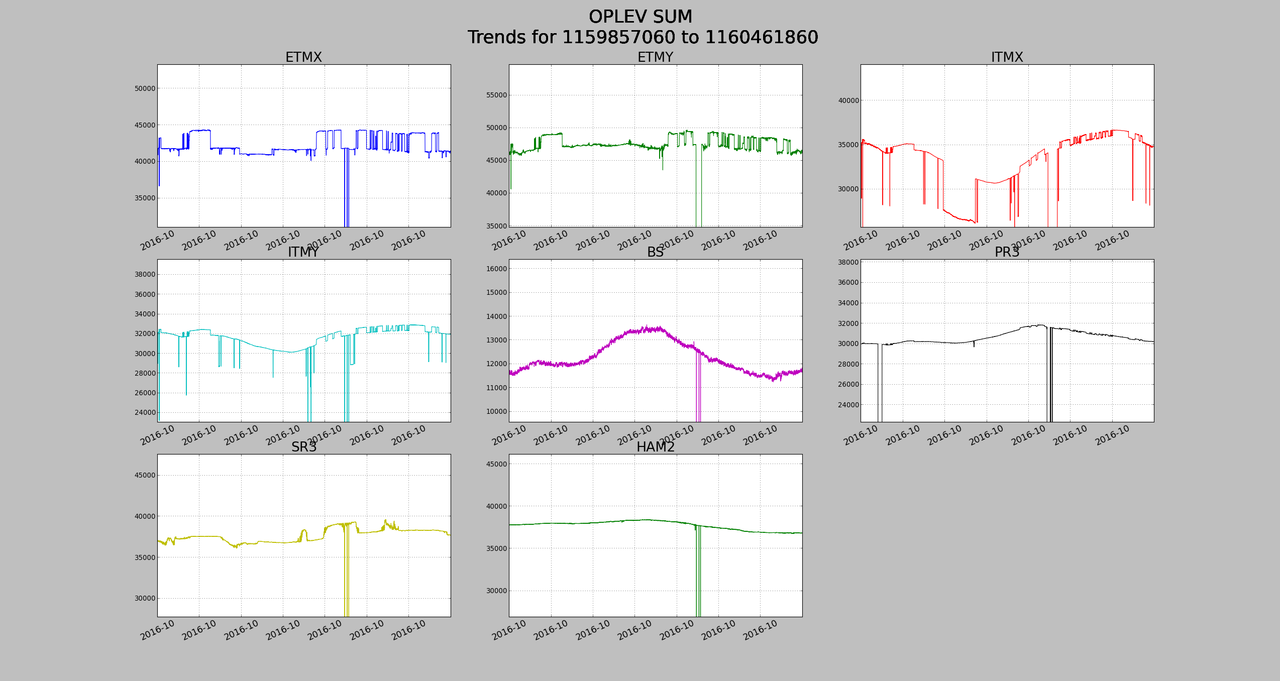
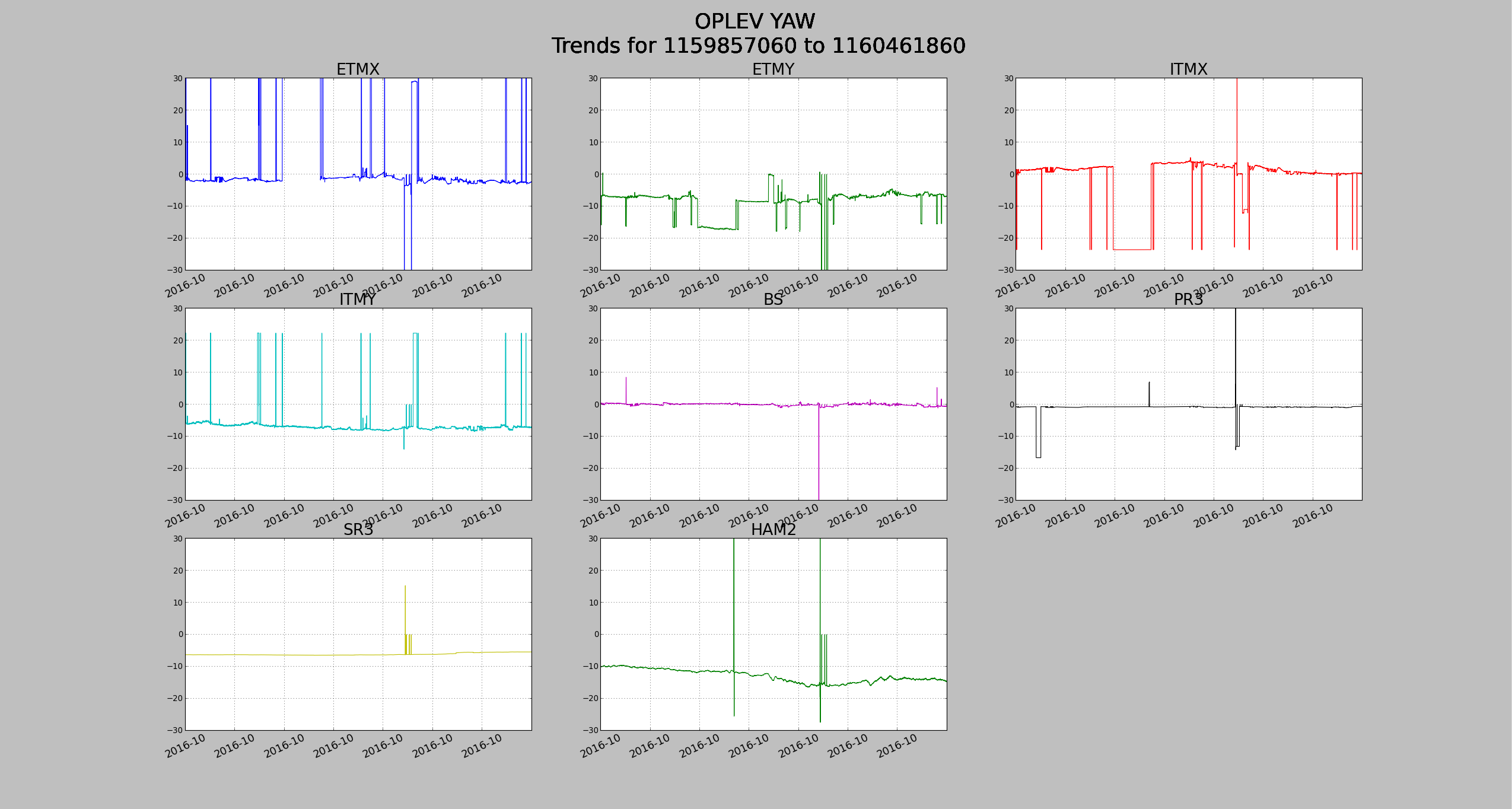
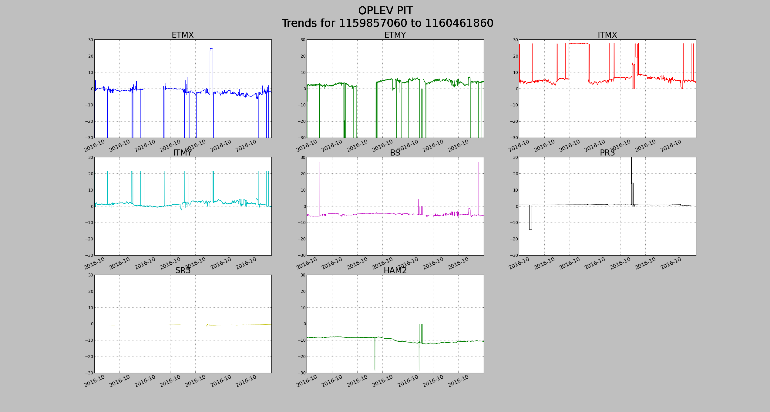
Nothing looks out of the ordinary with these trends. A re-centering should be done before the start of ER10.
Summary: I have moved the POP_A and SOFT offsets to find better recycling gain (31.2ish rather than the 29.5 we had been getting). I was hoping that this would help eliminate the peaks in the 200-900 Hz region, and I think it did a bit, although not as much as I'd hoped. It did help the high frequency noise "tail" though.
History: Some time ago, Sheila and I moved the POP_A offsets to improve the recycling gain from 25ish, and that worked very well and has been very consistent. At the time, we stopped where we did because the POP_X centering PZT was hitting its rail, not because we thought we had found the best possible location. Then, we elected to move on to trying to get to low noise rather than continuing to chase alignment offsets. Now that we're at low noise though, I wanted to see if continuing to move the QPD offsets would help get rid of some of this jitter / frequency noise coupling.
What I did:
In the end, the power recycling gain is about 31.2, whereas it used to be about 29.5 in NomLowNoise before this work. Also, as Jeff points out in alog 30481, it looks like this did good things for the DARM cavity pole and the optical gain.
At about 06:49:15 UTC, I had just about the lowest value for the broad peak at about 440 Hz. Going back to the offsets I had at the time did not reproduce that low of a peak though and the recycling gain wasn't at its maximum, so I ended up sticking with the offsets that maximized the power recycling gain. I may go back and look at the alignment of all the optics at that time to see if there was anything drastically different.
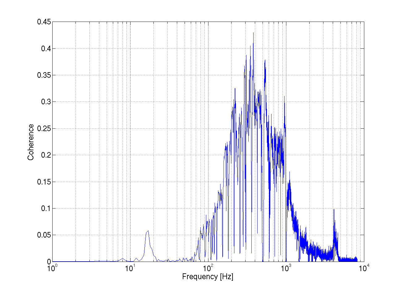
I also turned back on Gabriele's Jitter feedforward with the same gain of -1, and it still seems to be doing quite well. I haven't looked at the coherence, so I don't know if this is quite as good as when he and I were tuning it earlier today, but it still made a significant improvement in the 80 Hz - 250+ Hz region. I have this feedforward turning off in the Down state of the ISC_LOCK guardian, but it must still be turned on by hand. Once we're satisfied that it does good consistently, we can add it to NoiseTunings.
For now, I'm leaving the POP_A offsets in place, but the SOFT offsets will be turned off upon lockloss. I want to make sure that including them during the acquisition sequence isn't harmful to lock acquisition before accepting them permanently. I'm hoping though that they're fine, so that the ASC will handle all the SRM moving and we don't have to do anything by hand. To be checked tomorrow.
Offsets that I like in the end are:
Ideas:
I've now accepted all these offsets in SDF. We have locked at least once with the SOFT input offsets turned on at the same time the SOFT loops are engaged, and the SRM dither servo keeps things under control. So, I trended from the time that I set those offsets, and put those offsets into the transmon QPDs. I don't think we've locked yet with the offsets migrated to the transmon QPDs, so we'll watch for that being okay next acquisition. Attached are the sdfs for before/after values for convenience.

Sheila, Jenne, Kiwamu
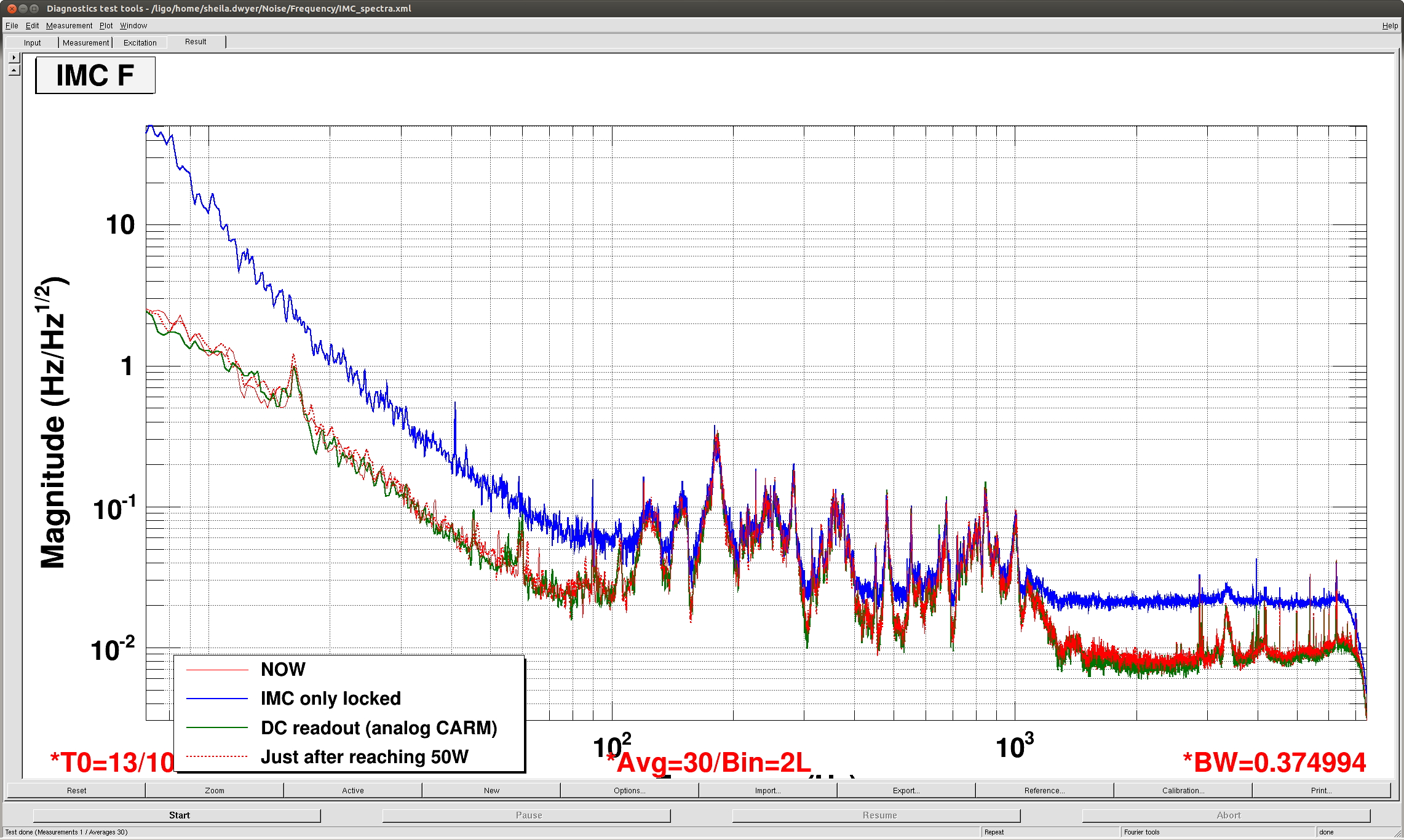
Attached is a spectra of IMC-F in different configurations. (MC locked at different powers, DC readout, low noise) From 100 Hz to about 1 kHZ, the spectrum of IMC F doesn't change much at all in all of these different configurations. So the IMC control signal is not dominated by REFL9 sensing noise in full lock, and probably represents the real frequency noise at the input to the IMC.
We can do a better job later, but if we assume this is really frequency noise we can roughly calibrate this into Watts on REFL 9I:
At 1kHz: 0.1Hz/rt Hz Frquency noise arriving at IMC (which is roughly consistent with measurements in P1100192, Fig 8) Suppresion of IMC loop: 1/200 (alog 22188) Supression of CARM loop (alog 22188, our ugf is now more like 8kHz) roughly a factor of 1/30. We can scale the DC optical gain of 0.017W/Hz used in 22188 by sqrt(2) to account for the factor of 2 increase in input power and the 6dB modulation index decrease since then. Taking into account the coupled cavity pole at 0.5 Hz give another factor of 1/2000:
0.1Hz/rtHz(1/200 Hz/Hz IMC supression )(1/30 Hz/Hz CARM suppression) (0.024*0.5/1000)W/Hz = 2e-10 Watts/rt Hz signal on REFL 9I or 1.7e-5 Hz/rt Hz of residual frequency noise expected.
We can repeat this at 400 Hz:
0.03Hz/rtHz(1/600 Hz/Hz IMC supression )(1/300 Hz/Hz CARM suppression) (0.024*0.5/400)W/Hz = 5e-12 Watts/rt Hz signal on REFL 9I or 1.7e-12 Hz/rt Hz of residual frequency noise expected.
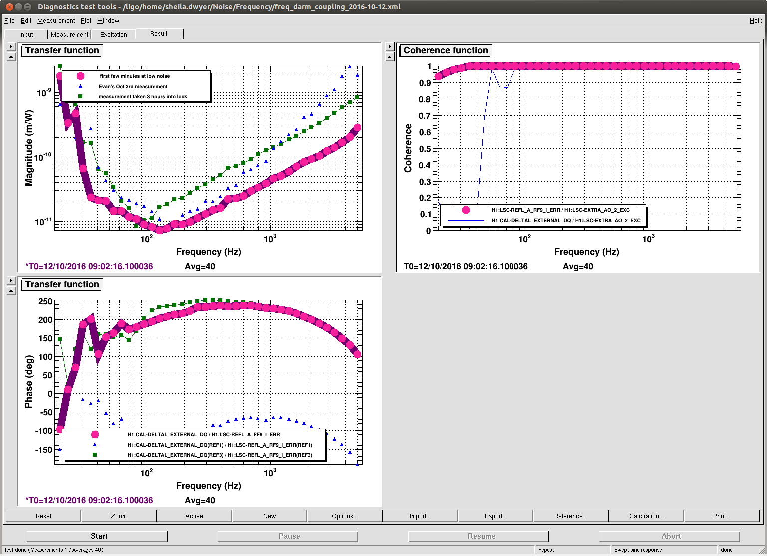
Comparing this to Evan's in loop measurement of the CARM noise using REFL control, (here) it is close at 1 kHz but not at 400 Hz. You can also compare it to the transfer functions from REFL 9I to DARM posted here, and see that at 1 kHz the expected frequency noise is of the order of 5e-20 m/rt Hz at 1 kHz.
The main message: It is probably worth making a projection for frequency noise in DARM using IMC-F to estimate the frequency noise after the ref cav, because a very rough estimate says it could be within a factor of 2 of DARM at 1kHz.
I just quickly tried changing gains on the FSS while watching the IMC F spectrum in full lock. The features from 100 Hz-1kHz do not change in IMC F as the FSS gain at these frequencies changed by 7 dB, so we are not limited by gain in the FSS at these frequencies. The FSS might have been oscillating at both the highest and lowest gain settings here.
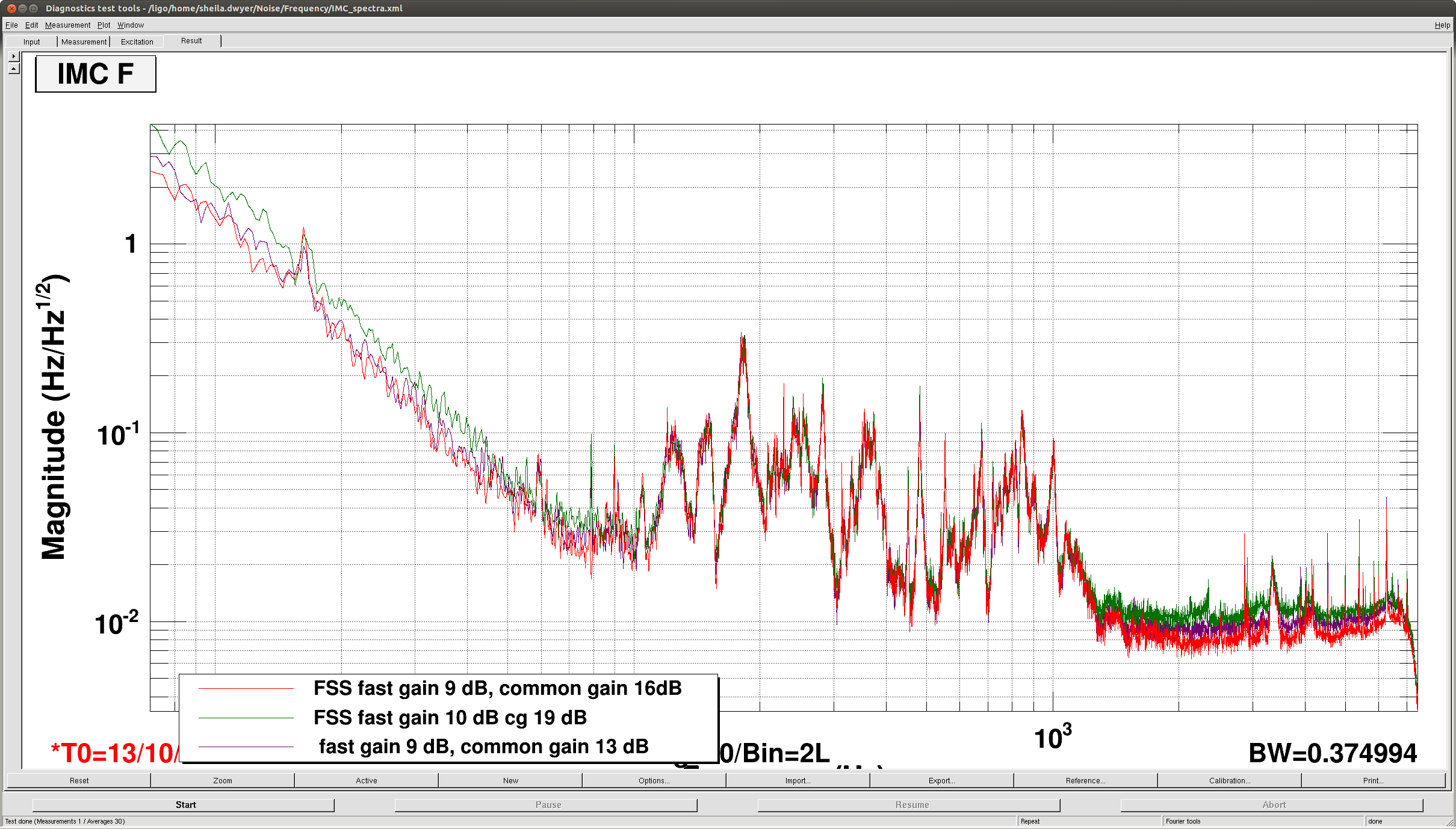
The gain at 1kHz from the IMC should be ~50 (ugf at 50 kHz) * 20 (boost) / 2 (mismatch between filter/cavity pole) ~ 500.
If the IMC gain is near 70 KHz one can probably kick in the second boost.
The noise level at high frequencies is 20 mHz/rtHz. Assuming this is the IMC shot noise at 2W, It would be at 4 mHz/rtHz at 50W. The VCO noise is around 2 mHz/rtHz at 1kHz. What we see is more like 8 mHz/rtHz, about twice higher than expected. Reference cavity?
The noise floor seen in IMCF with only the mode cleaner locked does not seem to be IMC diode shot noise, since it doesn't change as the input power is increased.


