Lisa, Kiwamu,
We think that the calibration has been wrong and therefore it lifted up the noise floor below 300 Hz. We need another set of eyes tomorrow to doublecheck our theory (we are currently too sleepy to do systematic investigation).
In short, we believe that the sign of ETMY L3 stage in CALCS (or somewhere else similar to it) is wrong which is exactly the same situation as what happened in this past July (28396).
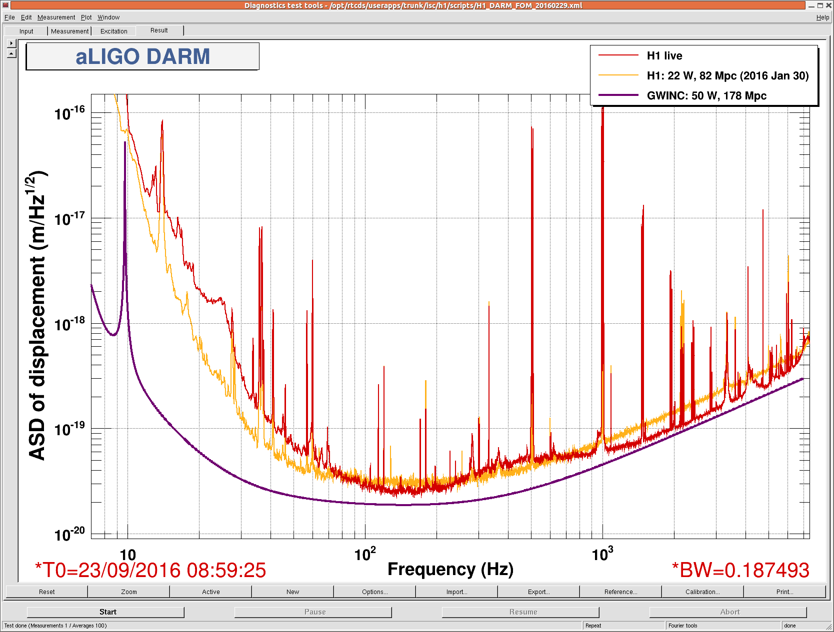
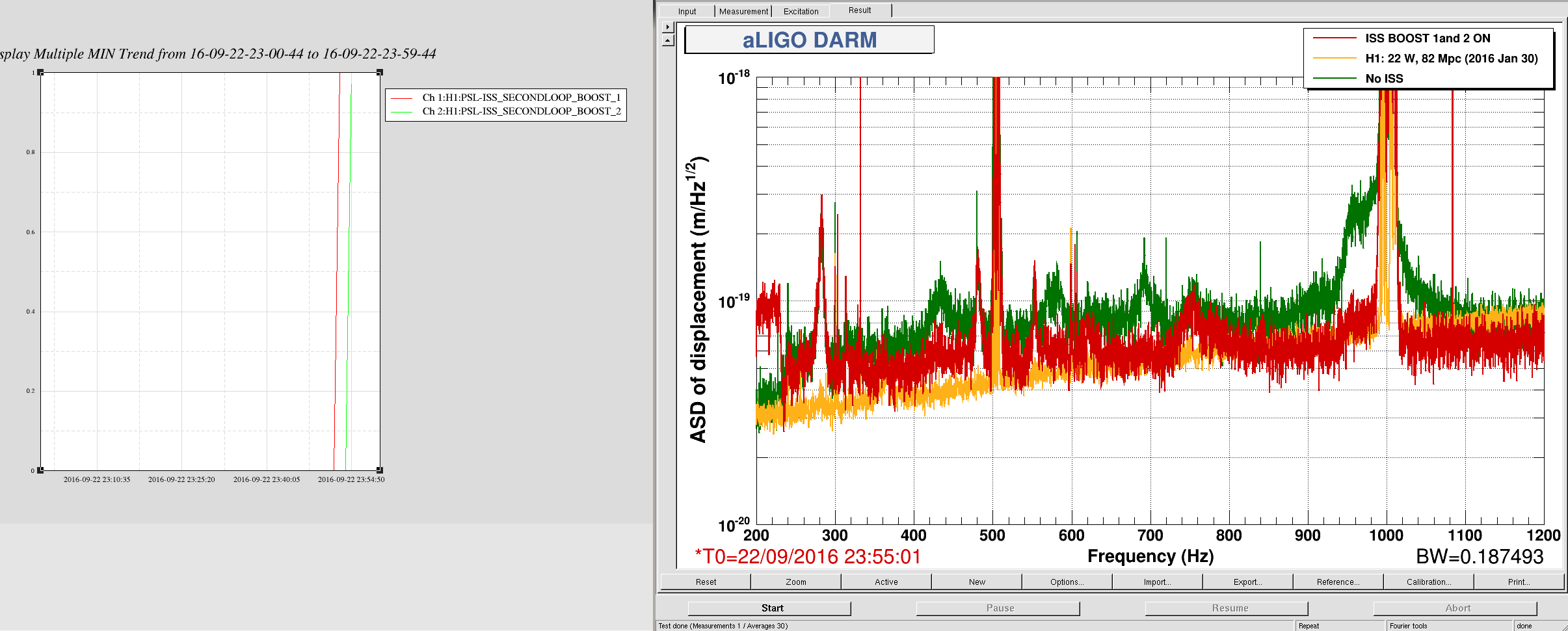
Because I knew that our DARM open loop model is accurate and consistent with the recent measurement (29748), I made a calibration filter for DARM_IN1 which converts DARM_IN1 to DARM displacement as opposed to the use of both DARM_IN1 and DARM_OUT. Here is a comparison of the CALCS spectrum against the spectrum derived from DARM_IN1.
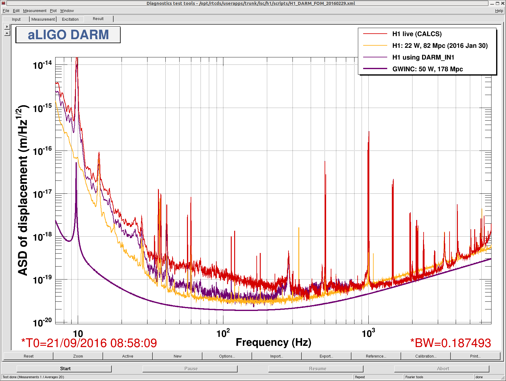
As shown in the plot, the CAL CS spectrum overestimates the noise floor below 300 Hz or so. This is exactly the same behavior as what we have experienced in this past July. In addition, we have noticed that the noise floor of CALCS changed as a function of the DARM control gain which should not happen in the calibration scheme used in CAL CS. Also, when we flipped the sign of the EY L3 stage in CAL CS, the leve of the noise floor became identical to the one derived by DARM_IN1 and also became insensitive to the control gain. This increased our confidence that the L3 sign was wrong in CALCS.
We are leaving the L3 stage gain flipped (DRIVEALIGN_GAIN -30 --> +30) for the night. If our theory is correct, we regain the binary range back to ~60 Mpc with this change.
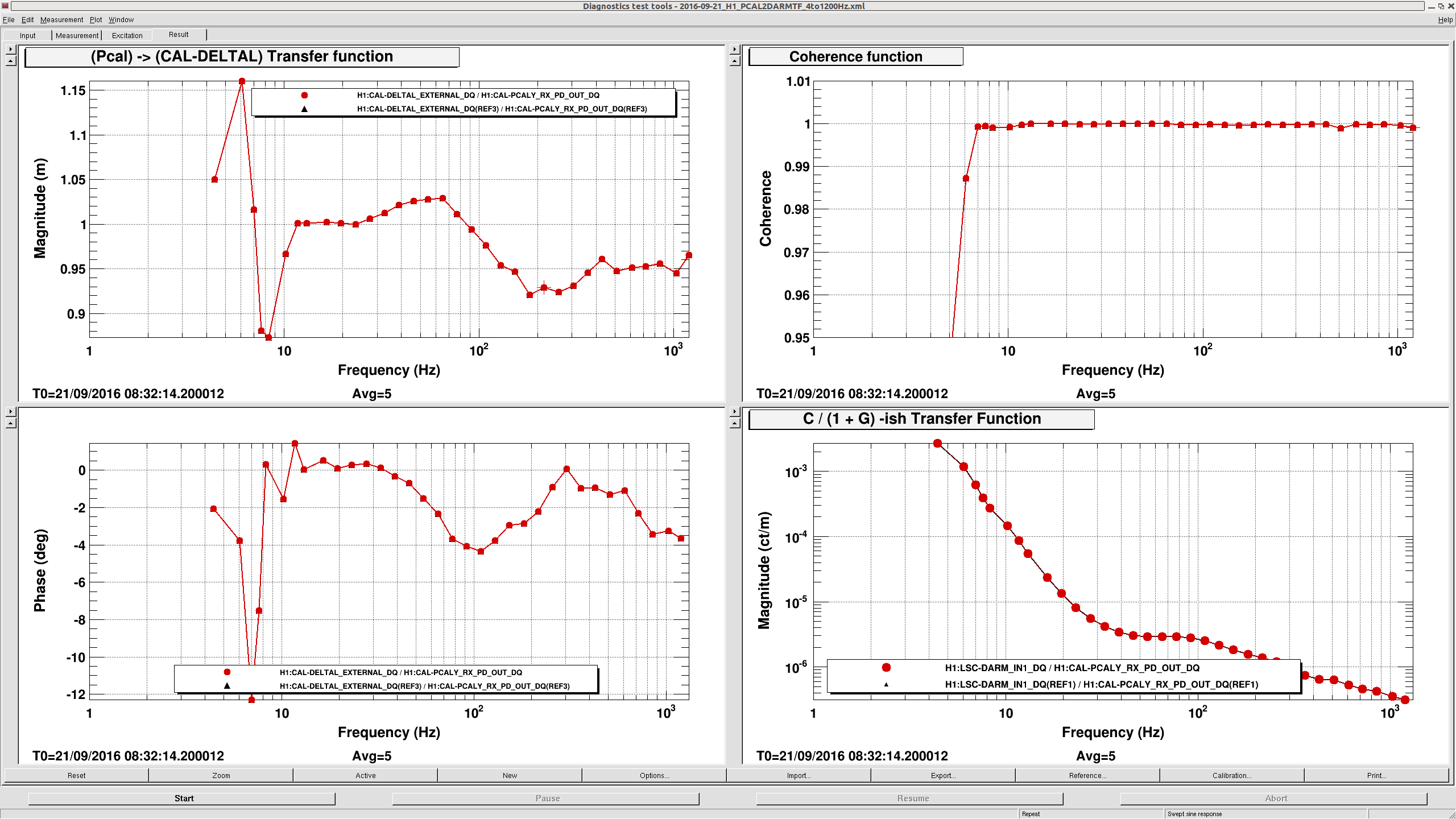
Also, we took a DARM open loop and PCAL sweep measurement within the same lock stretch. We did not analyze them yet, but they are available at:
/ligo/svncommon/CalSVN/aligocalibration/trunk/Runs/PreER10/H1/Measurements/PCAL/2016-09-21_H1_PCAL2DARMTF_4to1200Hz.xml
/ligo/svncommon/CalSVN/aligocalibration/trunk/Runs/PreER10/H1/Measurements/DARMOLGTFs/2016-09-21_H1_DARM_OLGTF_4to1200Hz.xml
Also, my code which generated the calibration filter for DARM_IN1, as well as, the generated filter are available at:
/ligo/svncommon/CalSVN/aligocalibration/trunk/Runs/PreER10/H1/Scripts/ControlRoomCalib/CalibrateH1DARM_IN1.m
/ligo/svncommon/CalSVN/aligocalibration/trunk/Runs/PreER10/H1/Scripts/ControlRoomCalib/DARM_IN1_calib.txt