We now see ETMY PI 18059 Hz (aliased down from 47477 Hz) MODE 28 ring up. It's been successfully damped several locks now with gain +10000, phase +90. These settings have been added to the guardian and SDF.
I believe this is the same pringle mechanical mode as the 18056 Hz which was originally seen back in July; there's no peak at 18056 Hz now and I was able to ring and damp this by driving ETMY ESD equally in opposite quadrants.
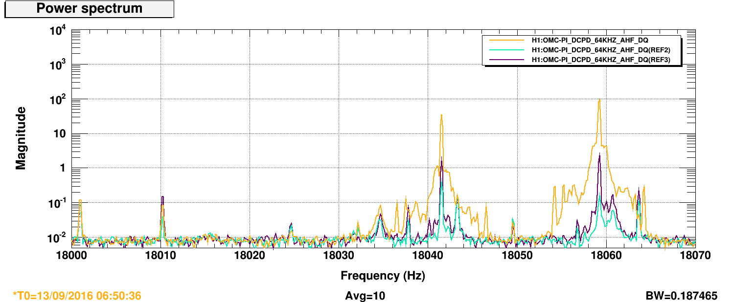
We've also been battling MODE 27 ETMY 18041 Hz (aliased down from 47495 Hz) the past two nights. Wonderfully, Slawomir just posted a study on these modes earlier this evening. Indeed, we do see both modes ringing up essentially simulataneously (attached: spectrum of three snapshots during the ring up last night. 18041 was being actively damped and 18059 had no damping).
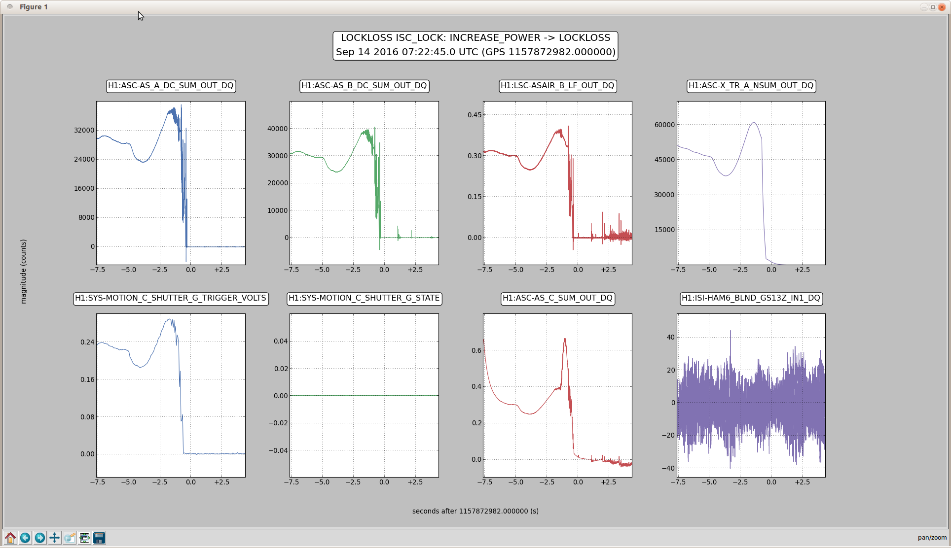
So far we've been unsuccessful at damping MODE 27. MODE 27 ring up very rapidly but for the past few months we've been quickly passing over it during the transient before it had a chance to ring up very much; the recent ring heater changes have shifted the optical mode so that's no longer the case. We had three tries to damp tonight, once with the usual BP + Damping filter set-up, once with PLL, once trying both. All were unsuccessful and we lost lock due to this PI. During this last lock, MODE 27 grew just enough that the drive started to saturate, consequently ringing up MODE 28. I was able to damp the latter by decreasing the gain of the former (and thus not saturating). During this time I tried PLL but it couldn't turn it around. After both seemed damped, MODE 27 rapidly rang up and broke lock. We need to find a smart way to handle stepping the gain to avoid saturation while balancing the need for strong drive. The PLL can do this (we can set a fixed number of counts out so as to avoid saturation) but the PLL doesn't seem to lock onto the modes until too late in the game. Perhaps we consider sending the OMC signal to the PLL for a try?