The most troubling environmental coupling in O1 was the vibration coupling at HAM6. Not only were ambient vibration levels within a factor of as little as 2 of the DARM floor around 1000 Hz, but the coupling was the only highly non-linear environmental coupling (https://alog.ligo-wa.caltech.edu/aLOG/index.php?callRep=23305, see especially summary attached to this log). Sound near 1000 Hz, and higher, could produce features in DARM at both higher and lower frequencies then the injection frequency. The fact that loud sound in the several thousands of Hz regions could down-convert into the detection band (one could imagine a chirp from the startup of a motor with squealing bearings) required special vetting (https://alog.ligo-la.caltech.edu/EVNT/index.php?callRep=11470). The non-linear coupling is due to intermodulation with the 4100 Hz OMC length dither frequency. I think that the most likely explanation is that there are frequencies starting at about 1000 Hz where ISI suspension, OMC suspension, and OMC body resonances all overlap, allowing vibrations from outside to significantly modulate the OMC length and intermodulate with the length dither. The overlap is probably made possible because the many resonances are not quite as high Q, and not as clustered as the optic suspension violin resonances.
We attacked the path in from the outside world by damping ISI blade spring and flexures (analogous to suspension wire) resonances during the June HAM6 intervention. I have previously logged that this damping reduced the desired ISI suspension peaks (https://alog.ligo-wa.caltech.edu/aLOG/index.php?callRep=27135), before we had the interferometer working. Figure 1, below, goes on to show that the damping resulted in a factor of about 3 reduction in vibration coupling to DARM, for a standard amplitude injection, for both linear and non-linear coupling (Figure 1 is for a shaker on the blue cross beams of HAM6; the measurement is for RMS in the band because the peaks moved around somewhat as well).
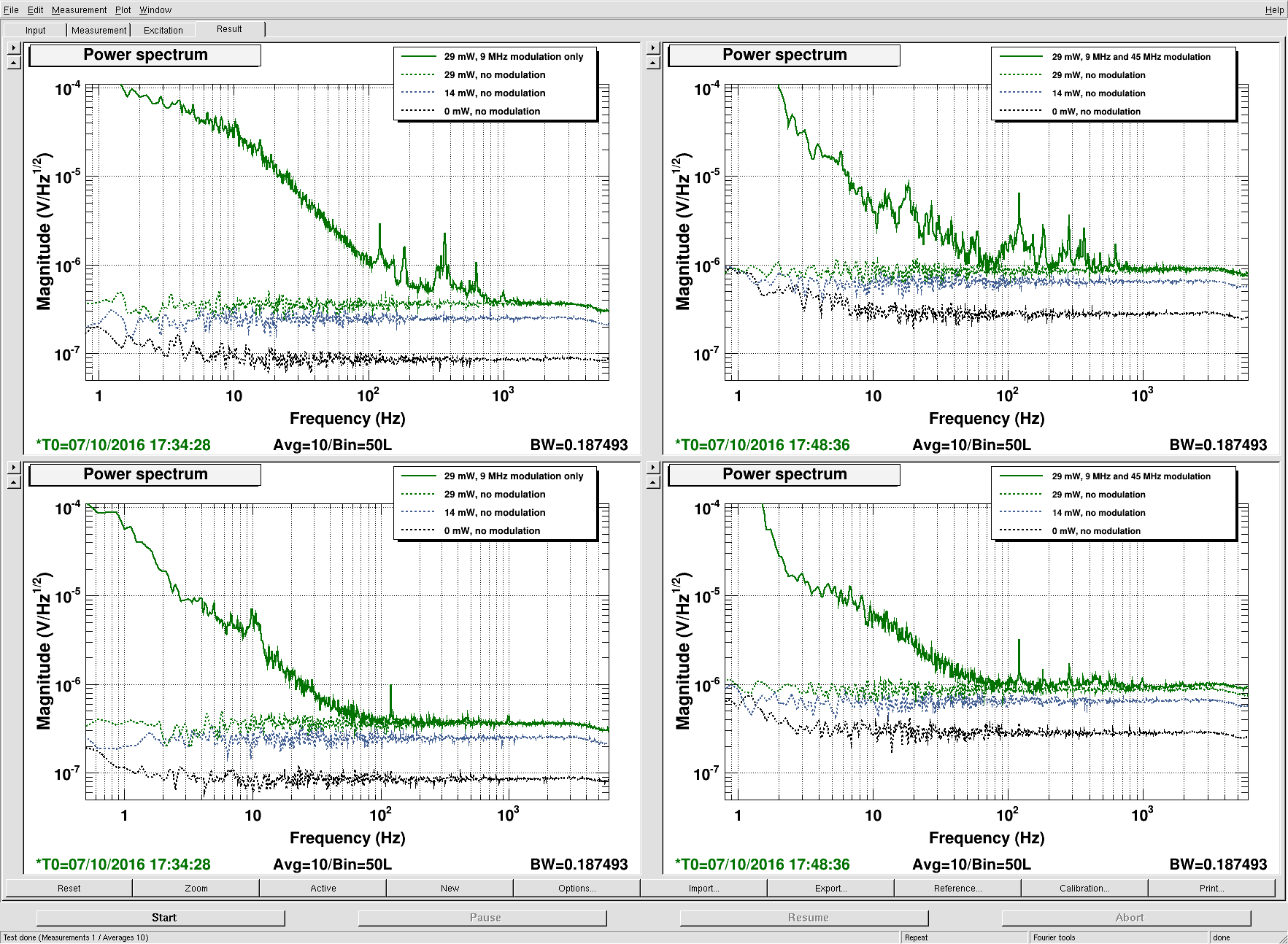
Figure 2 shows that we could further reduce the non-linear part of the coupling by reducing the dither amplitude. A factor of 8 (amplitude reduced from 6000 to 750, gain increased from 3 to 24 to compensate), gave a factor of roughly 8 reduction in non-linear coupling for a total reduction of more than 20. Figure 2 also shows that there was no apparent increase in noise at lower frequencies in DARM, and that the linear vibration coupling stays the same.
The previous figures were for targeted injections at HAM6 (blue cross beam shaking). Figure 3 confirms that dither reduction reduces non-linear coupling for global shaking from an acoustic injection with a speaker at the X-manifold standard location.
I propose that we try running with CLK_GAIN of 750 and SERVO gain of 24. The ISI suspension resonances were also damped at LLO, and I think the dither was reduced in Feb. for other problems associated with non-linearity. The sidebands in DARM at the dither frequency are, at LLO already the size of the sidebands for the proposed LHO settings, so LLO may not need to make further changes. Of course we should check.
Robert, Kiwamu, Anamaria