[Jenne, Terra, Koji, Ed]
Koji suspects that we might have a length offset in PRCL of about 1nm, so we tried giving PRCL an offset to see if that would help the recycling gain. Nope. Using the calibration for the PRCL error signal, Kiwamu told us that 1nm in PRCL is about 1,000 counts of offset. Empirically, about 100 counts of offset breaks the lock, and we don't see any change in the PRC gain. We'd expect a change of about 1 for 0.1nm if that were the true problem, so since we don't, we infer that PRCL length is not the source of all our PRC gain troubles.
After doing math today, I realized that yesterday's moves of about 16urad in IM3 corresponds to only about 50um in spot motion on PRM (IM4 is flat, 1.5889m between IM3 and PRM AR face according to E1200616). That's basically nothing. Tonight I moved much farther, and was able to see changes in the PRC gain, although I couldn't get it above 30. On the other hand, this was done without optimizing the soft offsets, so maybe we can get some more out of that.
I also tried moving the spot on PR2, but that didn't do anything for my recycling gain.
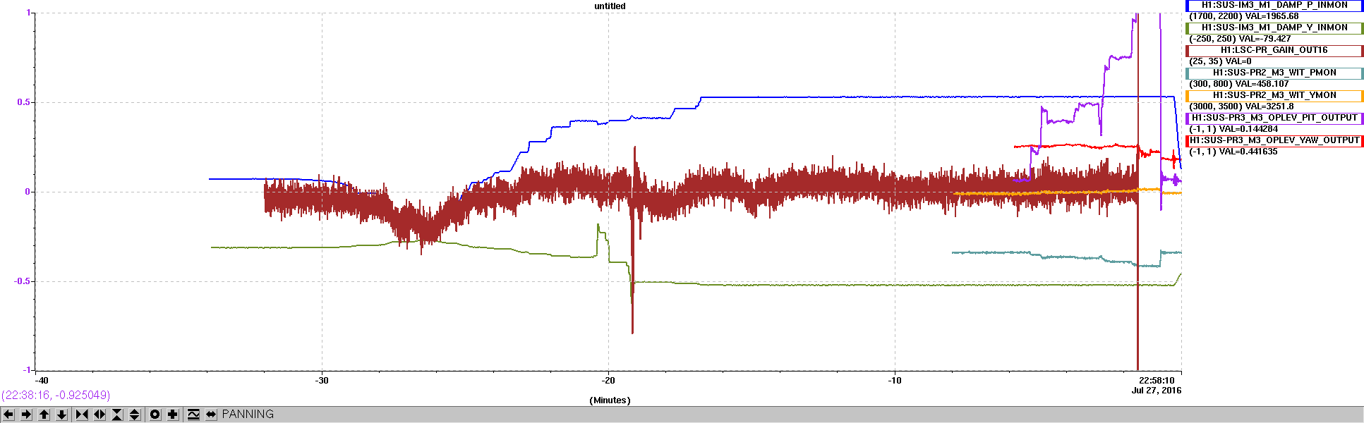
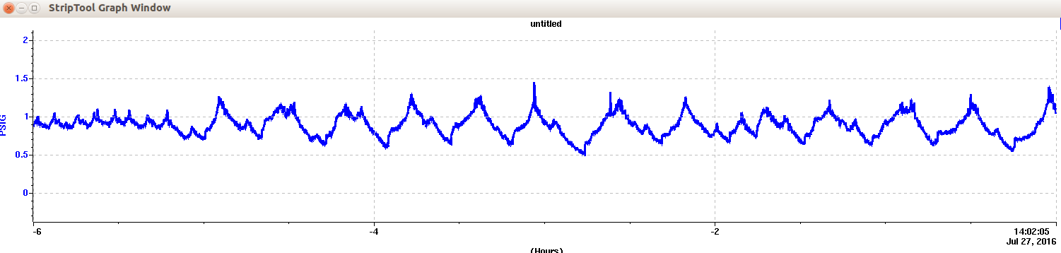
Also of note is that I was able to get more PRC gain out of PRC1 offsets by also including a yaw offset. In the end, I was happiest with +0.5 pitch offset, and +0.4 yaw offset. This is the starting PRC gain in the striptool plot below, before I got even more PRC gain from moving the PRM spot.
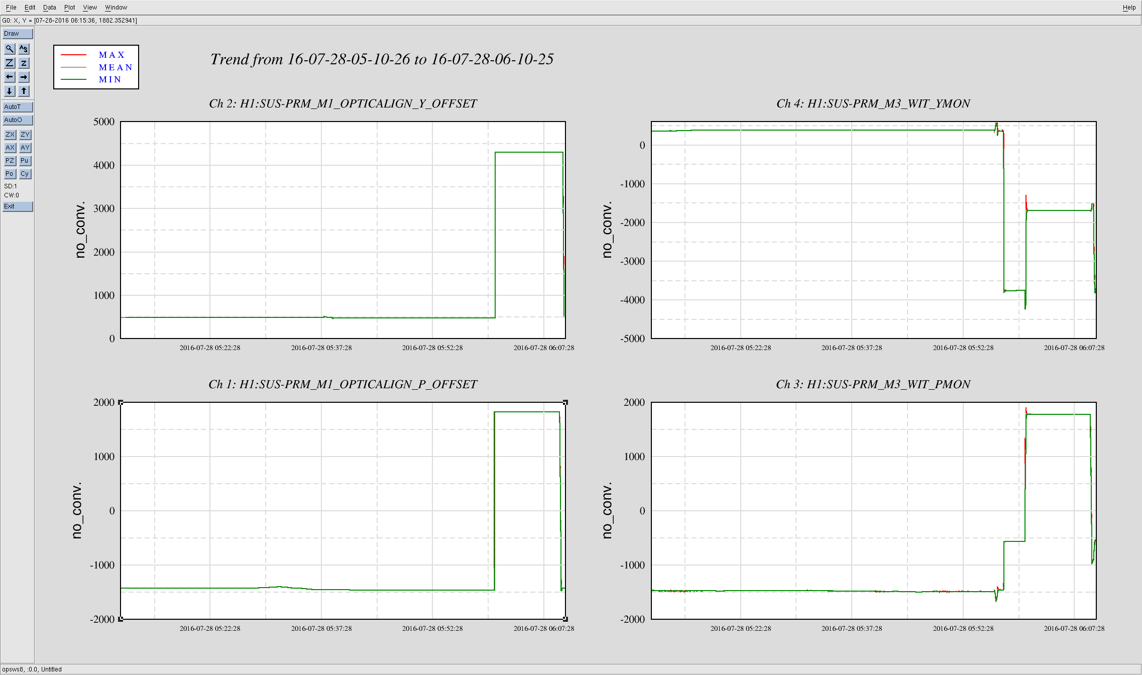
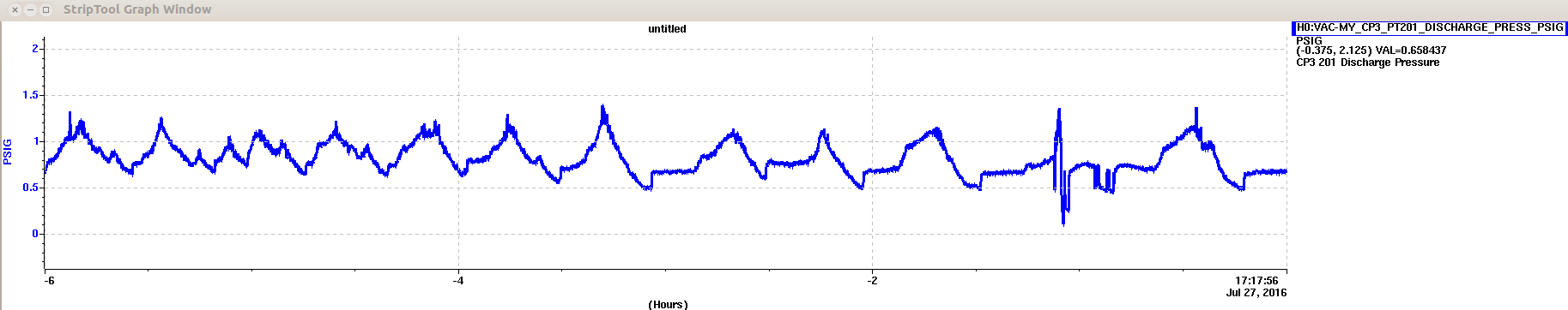
When we lost lock, the alignment was terrible, which is perhaps not too surprising. What is surprising is that somehow the PRM sliders got changed by more than 1,000 urad after the lockloss. In the PRM plot below, you can see that the OSEM readbacks start aligned, and the sliders are at some value. Then, at lockloss, the PRM is misaligned, so the sliders stay the same but the OSEMs read different values. Then, the sliders get moved. This should never happen, and isn't called for in any guardian that I (a) can find now or (b) have ever seen. Unclear what that was.
Just finished initial alignment, so the IFO is ready to go for the morning operator to start locking. With the OMC situation and my guardian "hack" (see alog 28686), you should be able to select IncreasePower basically any time after DRMI has locked, and everything else will run through smoothly and get you to 50W.