vernon.sandberg@LIGO.ORG - posted 07:58, Wednesday 05 October 2016 (30229)
Work Permit Summary for 2016 October 4
| Work Permit | Date | Description | alog |
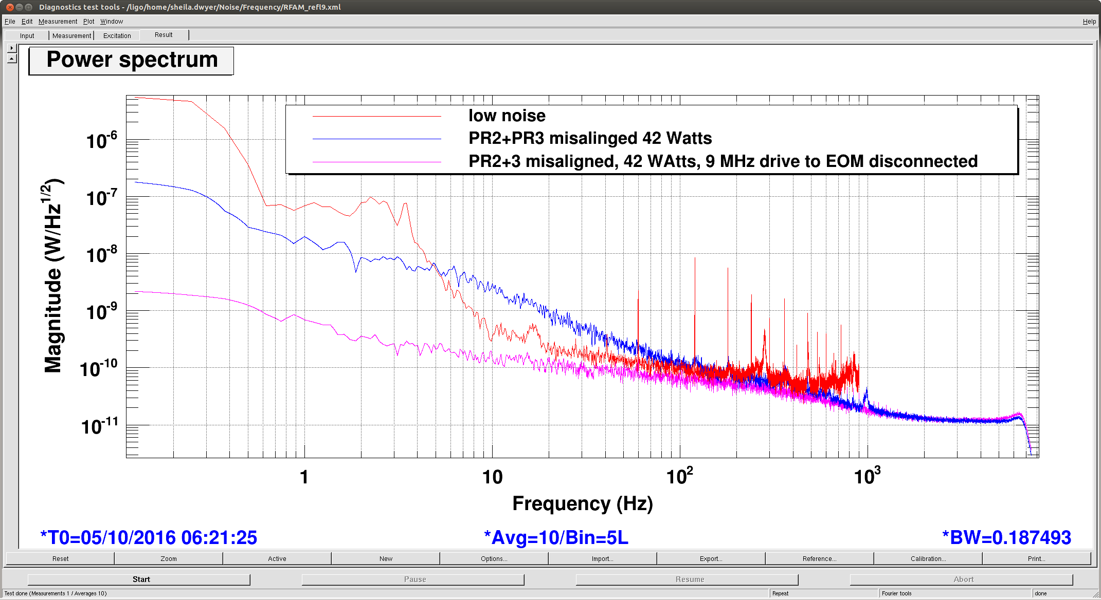
| 6215.html | 2016-10-04 15:43 | Activity: Replace QPD library block parts with the newer version that is already in use for the Transmon QPDs. This will allow proper lowpassing of our normalization signals. | 30214 |
| 6214.html | 2016-10-04 10:11 | Activity: add more memory to h1nds0. co-ordinate with Guardian reboot. | 30205 |
| 6213.html | 2016-10-04 09:03 | Activity: Look at Fast I monitors for ETMY to see why we have 4000ct offset. May be missing one leg of differential input. Per FRS 6114 | |
| 6212.html | 2016-10-04 08:32 | Activity: Replace HV Kepco power supplies with new ME Industries high voltage power supply for the ITM ESD LN Driver. | |
| 6211.html | 2016-10-03 14:46 | Activity: Replace binary card in SEIEY IO chassis. This is to address STS-2 remote centering not functioning. Front end and IO chassis will need to be restarted (FRS 4683). | 30207 |
| 6210.html | 2016-10-03 11:01 | Activity: Remote access (ssh) to the Seismon computer in order to investigate on some issues with the Seismon code (missing EQs). | |
| 6209.html | 2016-10-03 10:41 | Activity: Give tour to several professors from Beijing Normal University. | completed on Tuesday, Oct. 4, 2016 |
| 6208.html | 2016-10-03 10:33 | Activity: Minor guardian bugfix upgrade | 30180 |
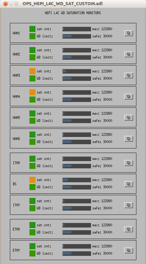
| 6207.html | 2016-10-03 08:54 | Activity: Investigate elevated noise on various CPSs: Cycle ISI state, power cycle satellite racks, unplug/replug cards, etc to reduce noise in sensors, ITMX, BS, ETMY | 30174 |
| 6206.html | 2016-10-03 08:41 | Activity: Update the calibration code on the DMT to gstlal-calibration-1.0.3-1 and restart hoft generation. | 30202 |
| 6205.html | 2016-10-03 08:22 | Activity: Crane scissor lift out of trapped corner near BSC 4 and meat locker and LTS containers. The scissor lift will be placed near the 3 IFO storage racks in the west bay. This exercise will require a laser safe condition in the LVEA. | |
| 6204.html | 2016-10-03 07:49 | Activity: Remove the socks and HEPA filters from the BSC cleanrooms over HAM1/2, HAM3, HAM4, and between the arms near the 3IFO storage area for cleaning. Vacuum and/or wipe roofs of the cleanrooms. | |
| 6203.html | 2016-09-30 13:56 | Activity: Drive photographer for Science magazine down x-arm to site for photo oportunities | done |
| 6202.html | 2016-09-30 11:50 | Activity: Install a new build of the daqd fw on h1fw2. This is continued testing on the build of daqd that will be in the next tagged release. We want to test on h1fw2 as it receives the full data stream, but does not write its results out to ldas, so is a low risk site for testing on the production system. | |
| 6201.html | 2016-09-30 11:26 | Activity: Remove Symantec Antivirus on Beckhoff computers h1ecatc1 & h1ecaty1 | |
| 6200.html | 2016-09-30 10:46 | Activity: Science Magazine photographer Bill Douthitt will be on site Friday Sep 30 to scout the site for locations to shoot for an end-of-year article on GWs and LIGO. He will shoot at dawn and dusk, potentially Sat Oct 1 - Mon Oct 3. Amber will chaperon on Friday, but Douthitt will potentially shoot dusk/dawn on the weekend from outside, without accompaniment, if we are satisfied he understands our constraints. | |
| 6199.html | 2016-09-29 13:40 | Activity: increase h1nds0 memory to 48GB to be the same as h1nds1. | 30071 |
| 6198.html | 2016-09-29 08:52 | Activity: Re-terminate bad pin on DB37 binary connector for the AS-C QPD whitening Chassis. | |
| 6197.html | 2016-09-29 08:51 | Activity: Replace faulty power switch on h1lsc0 IO chassis. Front end and IO chassis will need to be powered down. | |
| 6196.html | 2016-09-28 15:31 | Activity: Pcal beam localization work. Access to ENDX and ENDY | |
| Older WPs | |||
| 6195.html | 2016-09-27 15:22 | Activity: add task Work Permit field to the reservation system. This is an additional argument to make_reservation and an additional column in display_reservation. Area of Activity: Reservation system | 30056 |
| 6179.html | 2016-09-22 11:23 | Activity: to fix fw instability, power cycle fw and solaris ldas-gw systems. Sequential restarts to preserve data. | 30167 |
| 6053.html | 2016-08-04 07:38 | Activity: Add capacitor from HV stage to LV stage per ECR E1600230. This is to allow PI signals to work in both HV and LV states. This will take each end ESD down for hour or so each. Area of Activity: ETMx Low Voltage ESD driver | 28939 |


[Jenne, JeffK, Terra, JeffB, Cheryl]
A consequence of this degredation of HPO ouput power is that we have less power incident on the rotation stage's HWP, so the maximum amount of power that we can inject into the vacuum is lower than it has been.
We can and should address this by recalibrating the rotation stage such that we are getting the power we request (after other fixes listed below). But, right now the max power we have available is 48.5W, even if we request more. (Normally one could "cheat" and request some power higher than 50W to get actually 50W, but we can't do that here).
I see 2 possible solutions to this:
I leave it to persons more expert than myself to determine which of these is better. I know that Peter already increased the diode currents this morning (top entry in this thread), so maybe we don't want to do that anymore. But, adjusting the HWP requires a PSL incursion.