Evan H., Jenne, Matt, Kiwamu,
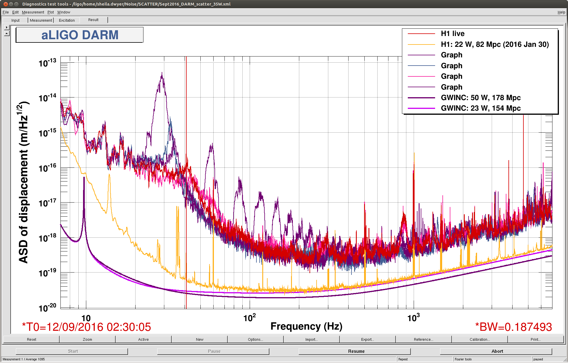
We locked the interferometer at 50 W with the latest ring heater setting (RHX = 0.5 W, RHY = 2.5 W, 29588). So far the interferometer has been locked at 50 W for roughly 1 hour.
P.S. we have now having difficulty damping a PI mode (mode2, 15520 ITMX) and decreased the PSL power back to 30 W.
[DRMI lock on POP sensors]
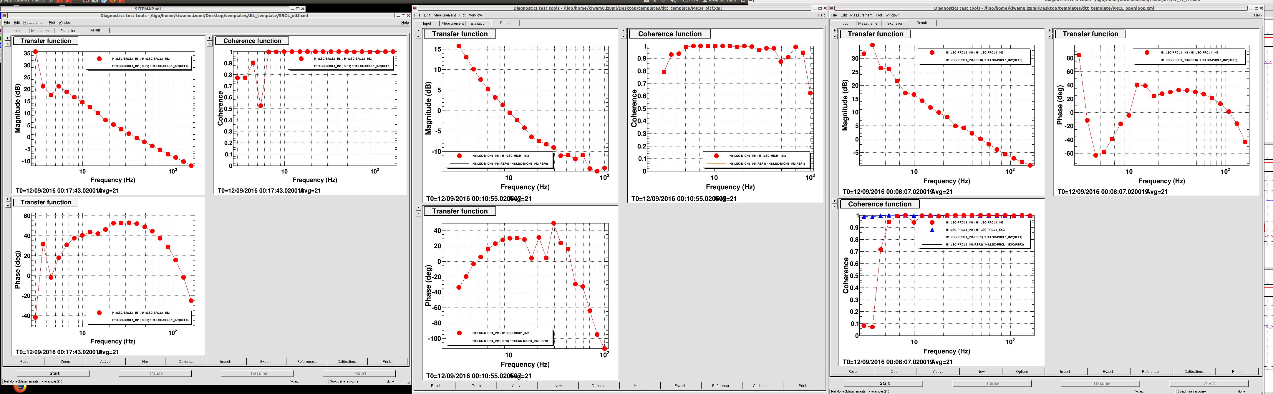
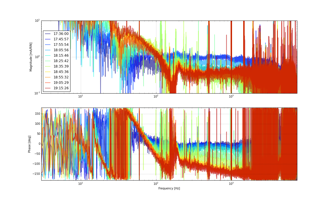
As reported yesterday (29601), we had a difficulty in switcing the sensors from the 3fs to 1fs earlier today (29603). In the end, I manually executed the sensor switch process one by one and for some reasons this was successful. I then measured the open loop transfer functions of the DRMI LSC degrees of freedom, but they looked OK. See the first attachjment. This may be due to that we did not wait for long enough time to let the new CO2 setting settle (29603) for lock acquisition ([CO2X, CO2Y] = [500 mW, 1000 mW]). Not sure.
Also, in lock acquisition, I manually kept aligning PR3 when the interferometer was at ANALOG_CARM in order to maintain the lock.
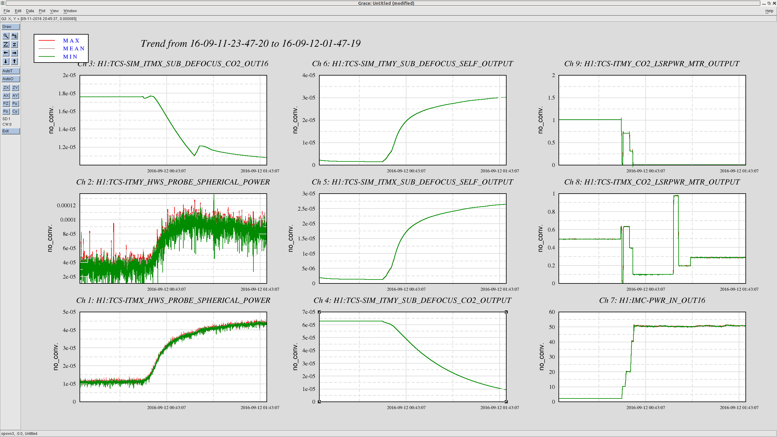
[CO2 tuning at 50 W]
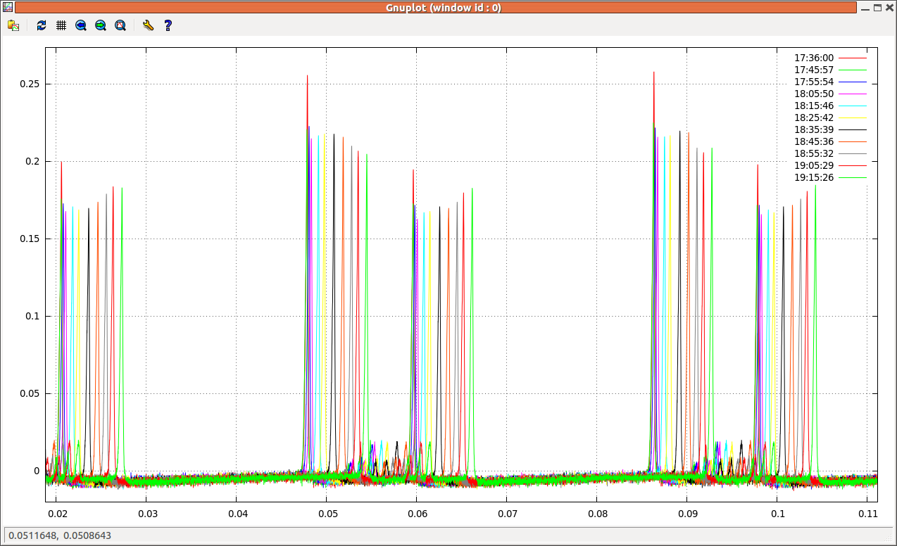
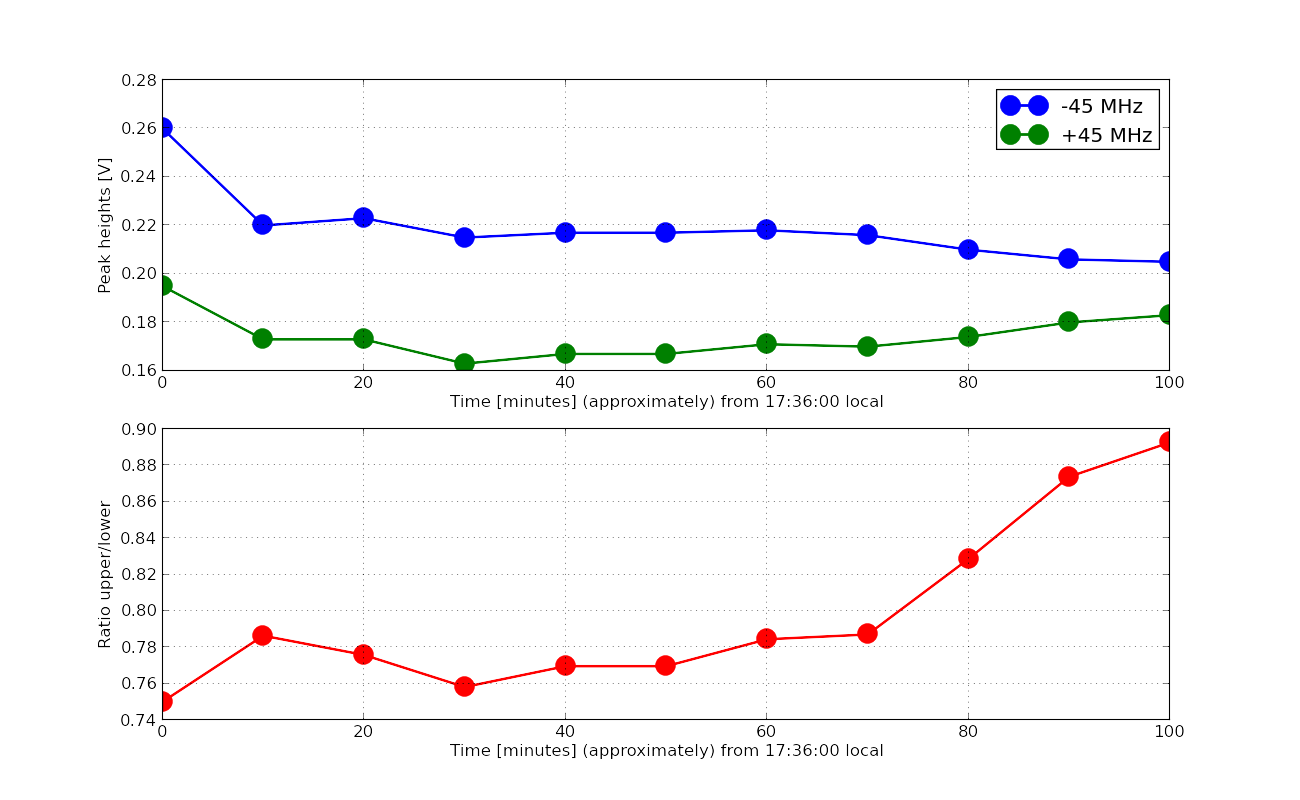
This is not well tuned, but the below is an OK CO2 tuning for 50 W which gave us a 30% imbalance at the AS port OSA.
[CO2X, CO2Y ] = [300 -400 mW, 0W]
This time I did not spend time for tuning the dCO2 at 20 W or 40 W. Maybe I should have done that to collect more data points.
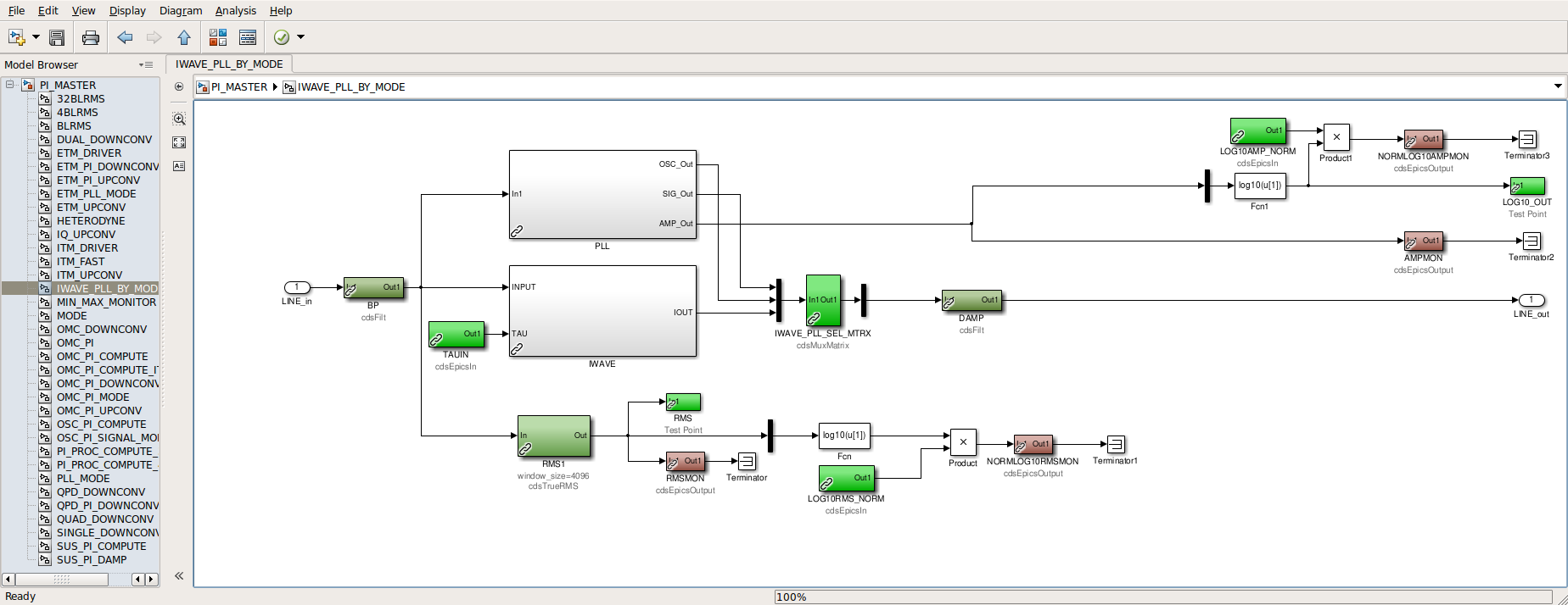
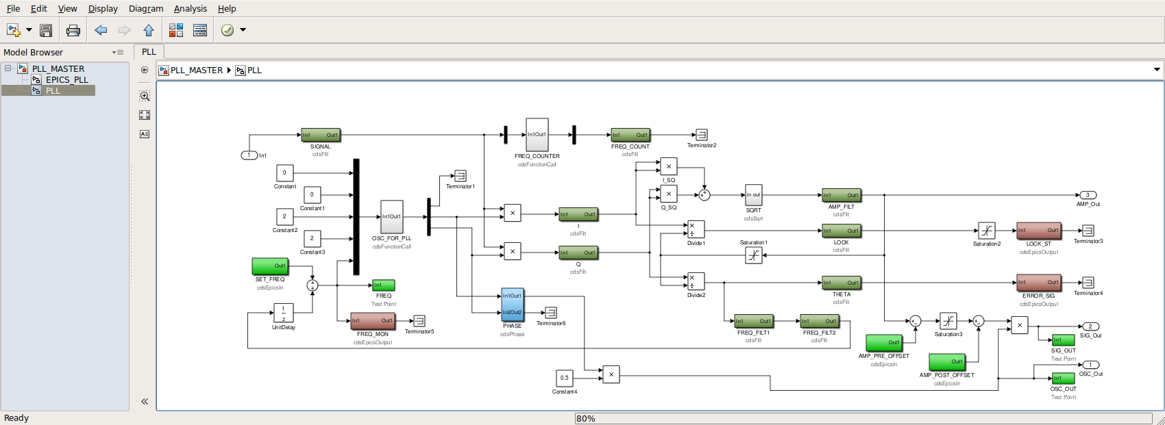
[PIs]
MODEs 17 and 27 needed a sign flip. Mode 27 seems tricky -- every time when it rang up we needed to flip the control sign.