Jenne, Stefan
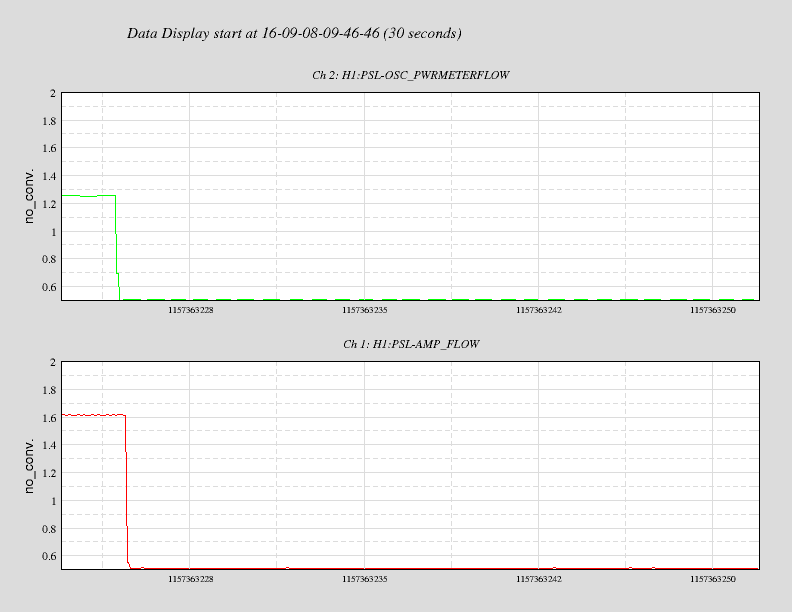
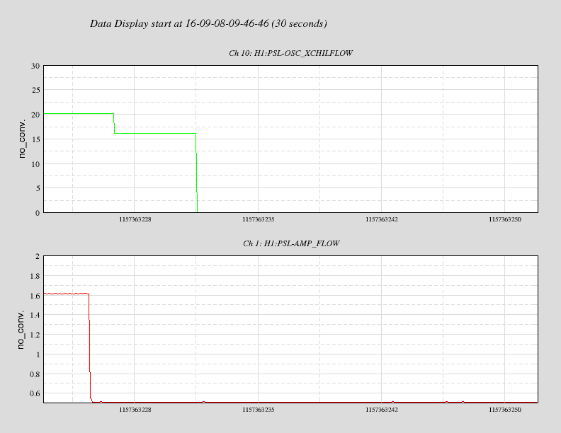
- lowered CFSOF gain from 0.5 to 0.2. This avoids an instability due to gain peaking and possible radiation pressure feed-back at 2.15Hz.
- With that the coil driver switching was no longer an issue. In fact we reduced the ramp times all to 1 sec - it worked fine.
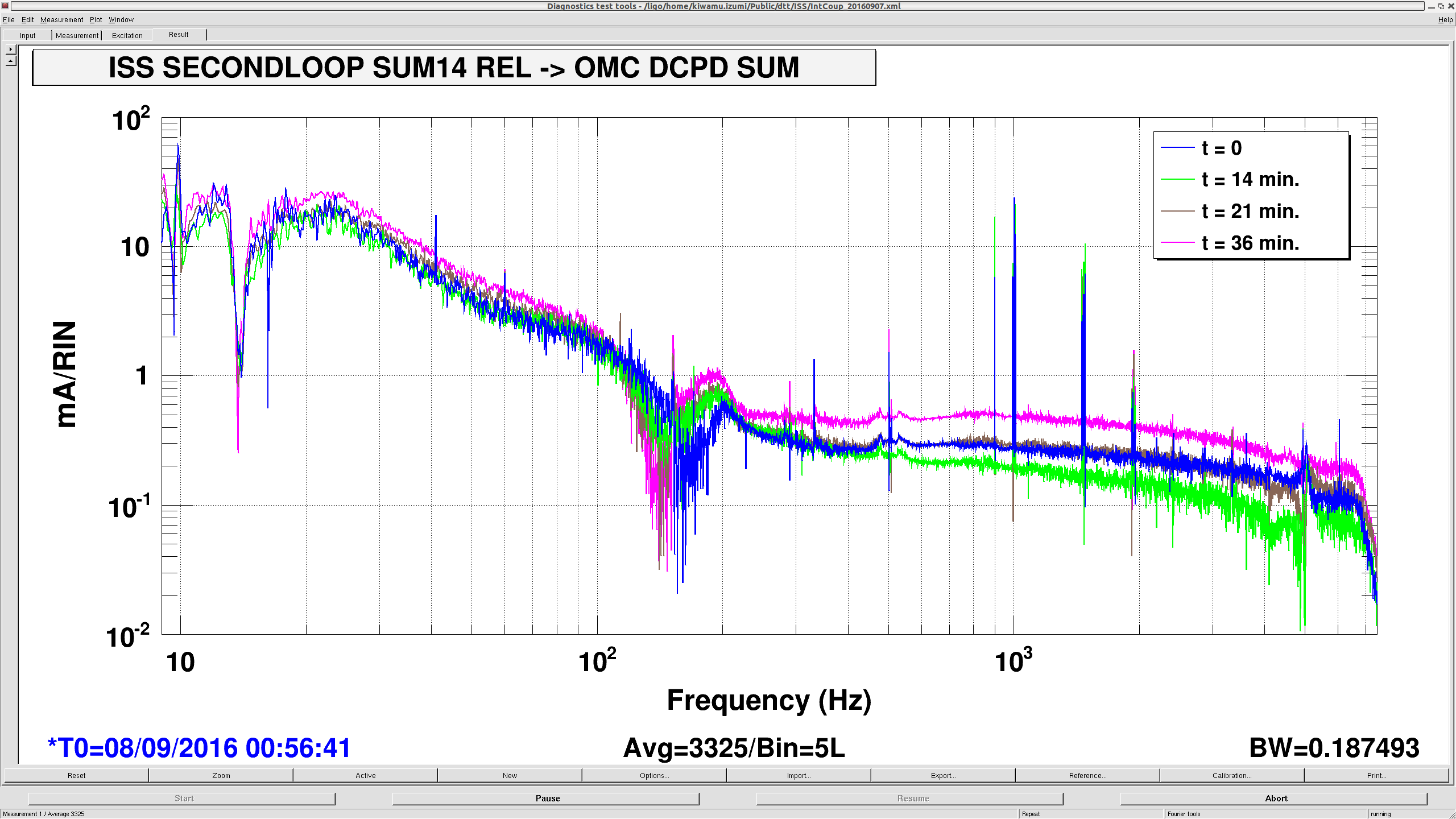
- We still keep dropping the sideband recycling gain and lost lock after ~36min. THus we decided to do some loop gain tracking.
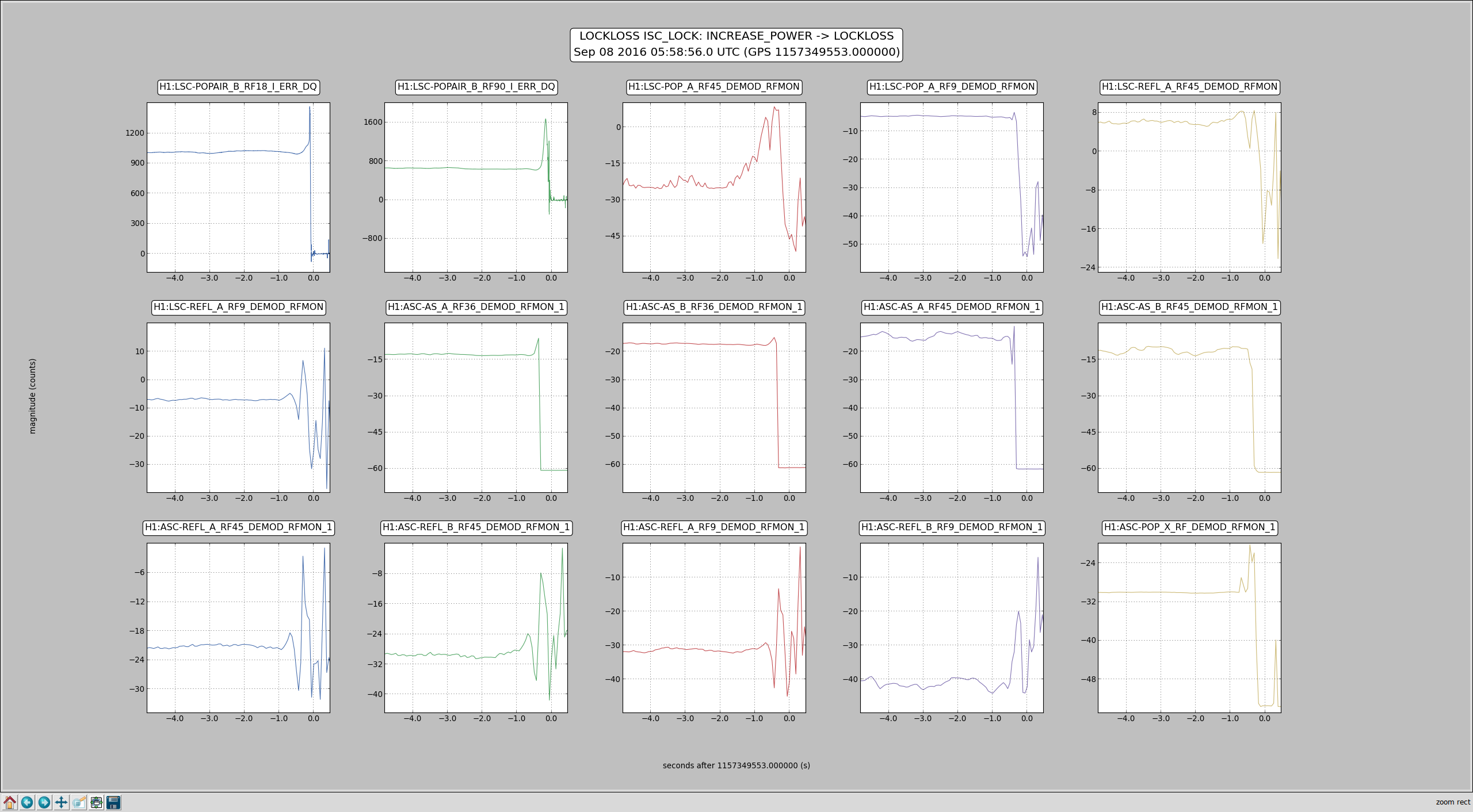
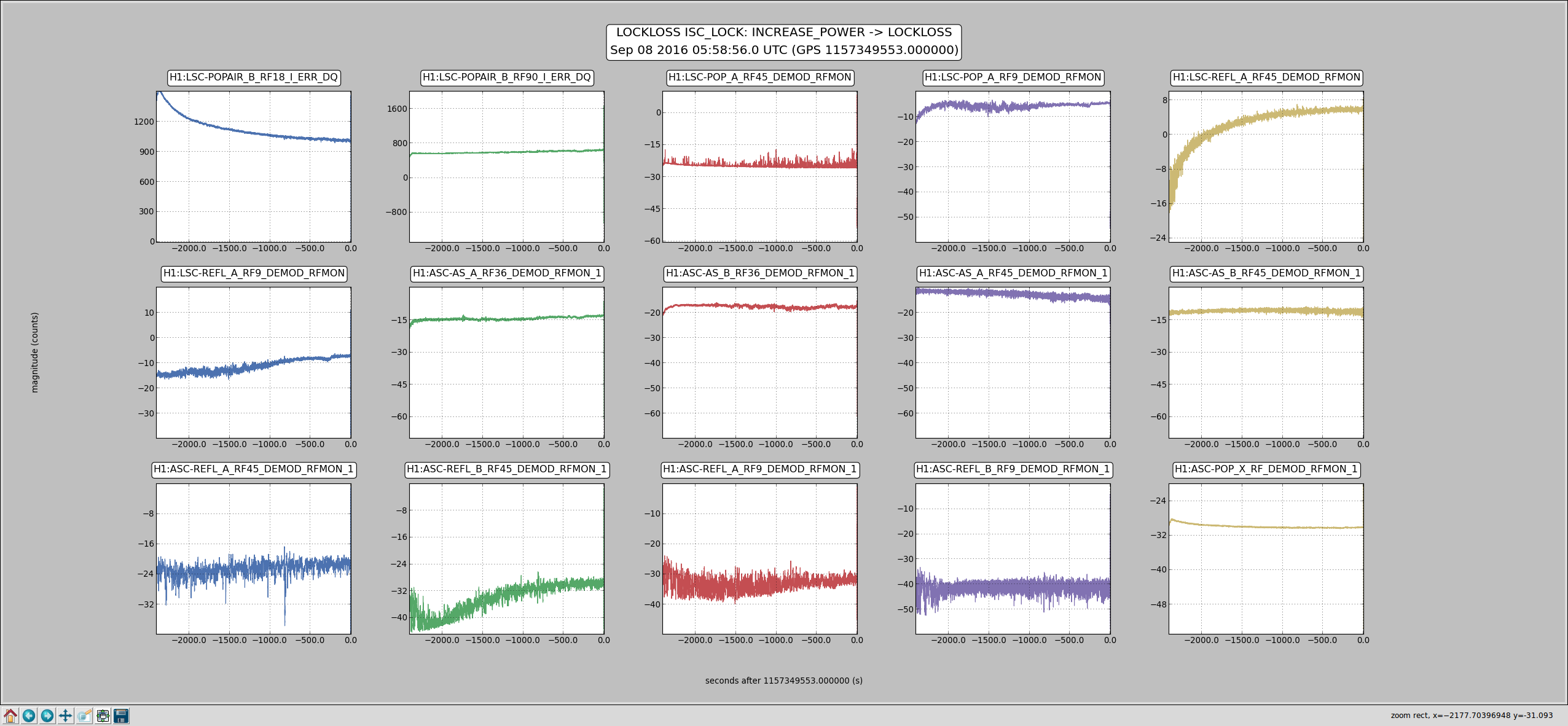
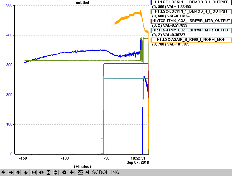
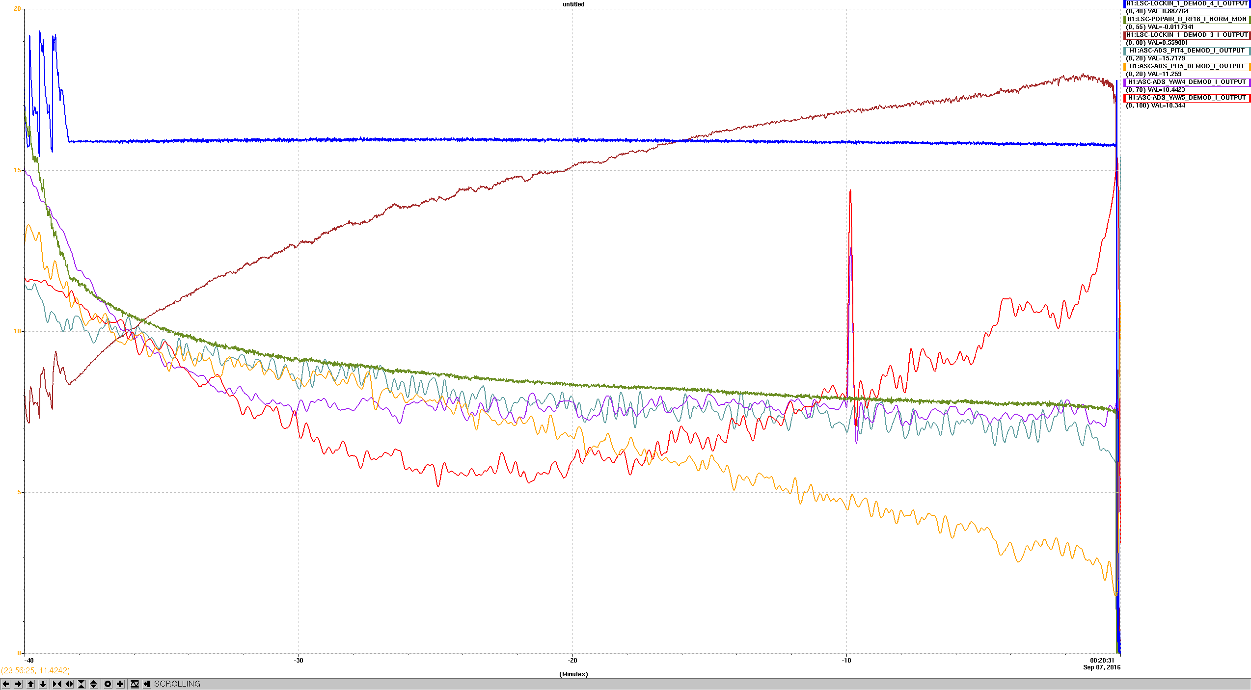
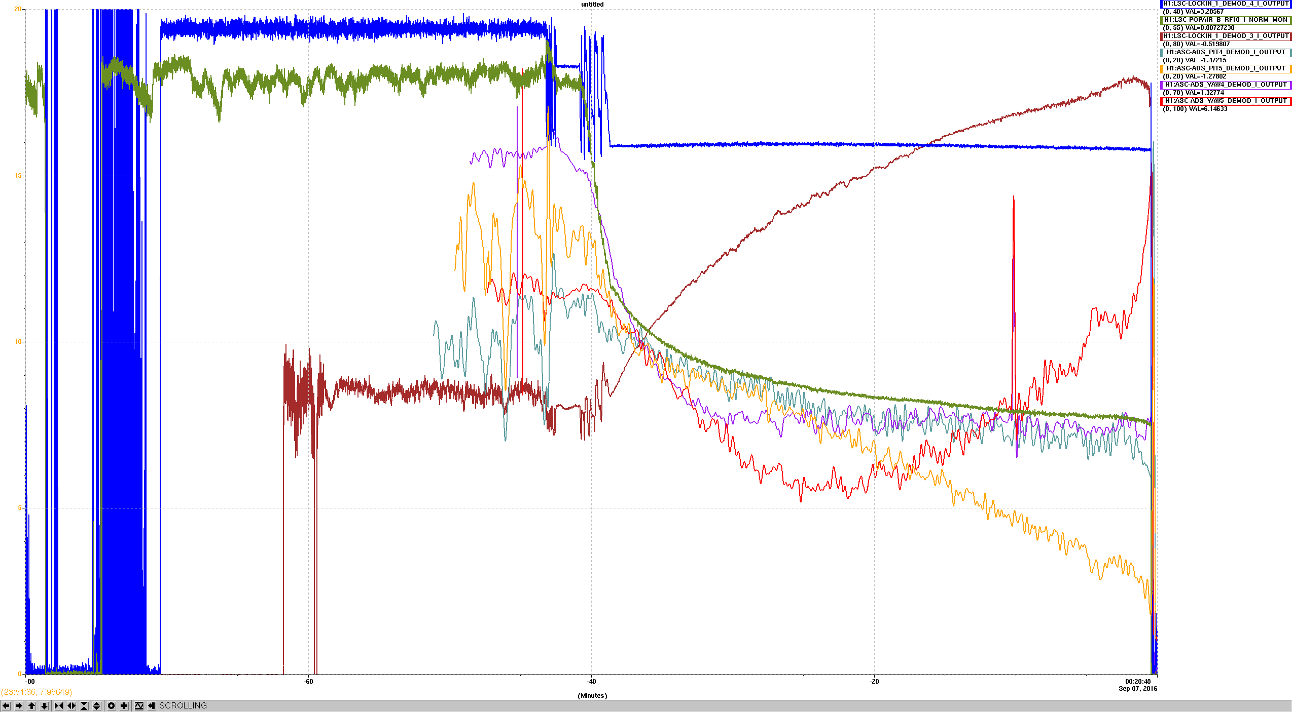
- We added a laser frequency modulation line at 900Hz, and demodulated it in REFL_9_I (blue - LSC-LOCKINM_1_DEMOD_4_I) and REFL_45_I (brown - LSC-LOCKINM_1_DEMOD_3_I in the attached plot).
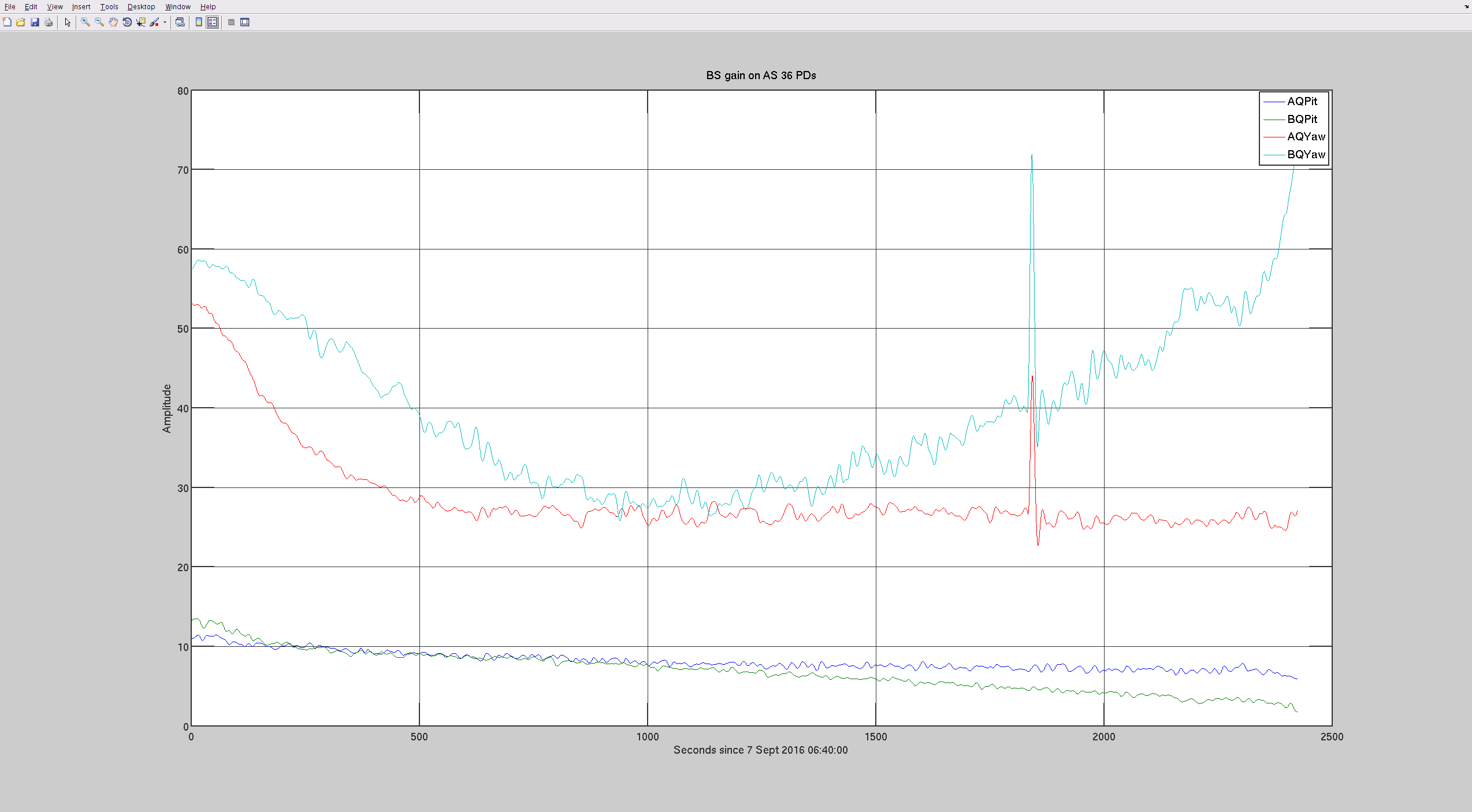
- Additionally we suspected that the BS ASC controls are going wacko. So we but pitch and yaw dither lines on the BS, and demodulated everything.
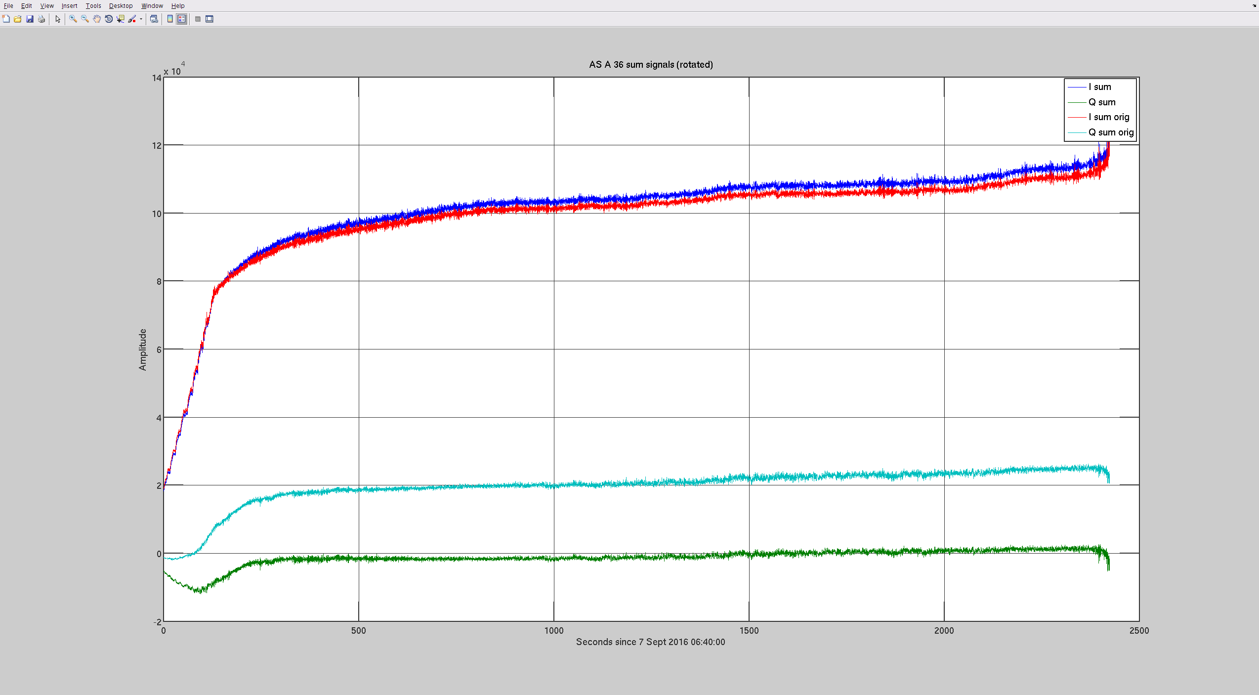
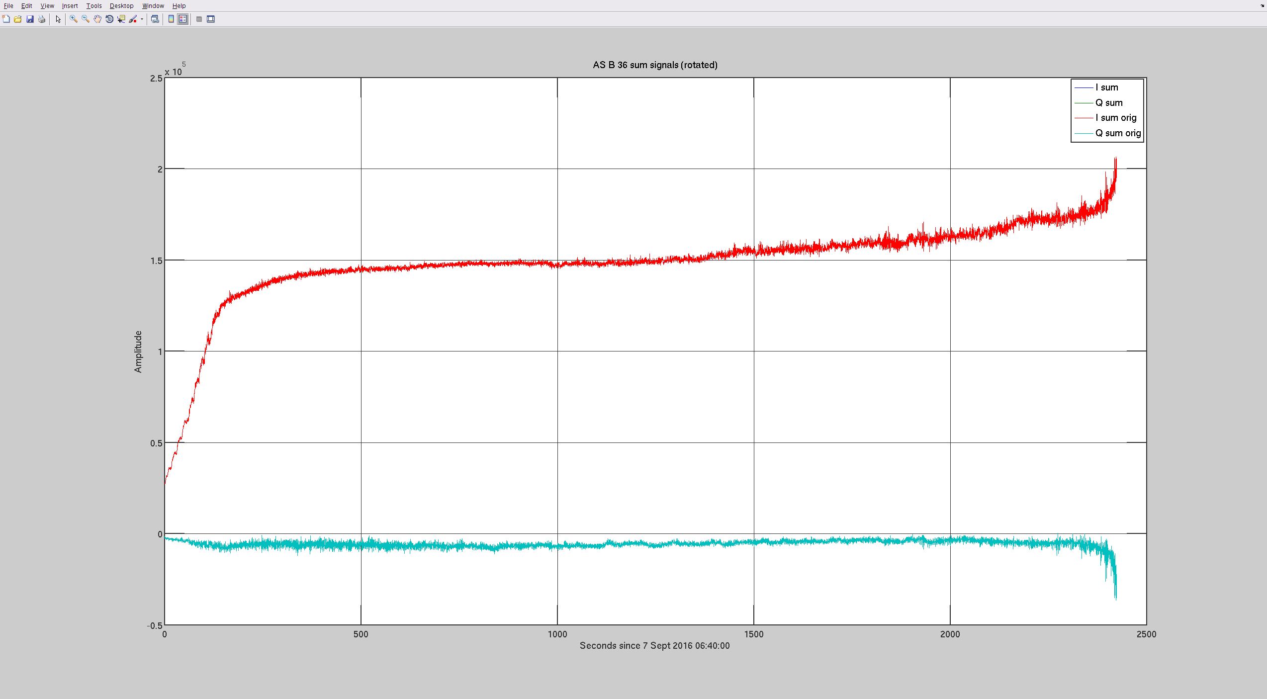
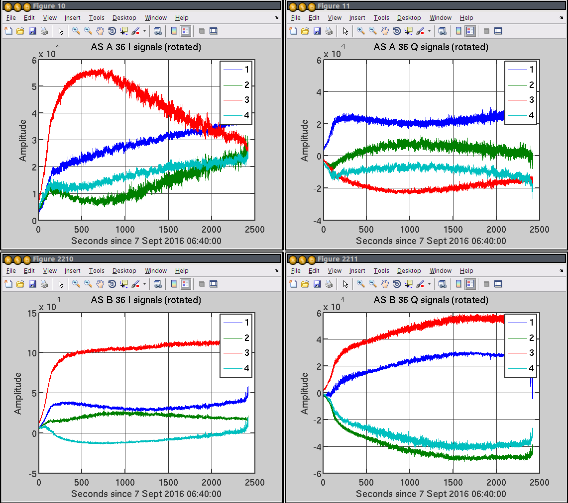
- Attached are two plots (with different time axis) of the result during a 50W lock.
Remarks:
- The REFL45 gain INCREASED by more than a factor of 2! This is consistent with less 45 sideband going into the cavity, and thus more being available as reference in REFL.
- The AS36_A gains seem to reflect that - i.e. a slight gain drop due to less 45MHz being available.
- The AS36_B gains initally agree, but then go completely nuts: AS36_B_Q_P (orange) keeps dropping, while AS36_B_Q_Y (red) turns around.
- Additionally, the AS36_B_Q_Y- Q dither demoduilation is growing significantly (not plotted). Not sure what to make of that. (the Q dither demodulation of all other signals remaind reasonable.)
Conclusion:
- We suspect that our lock losses might be due to the BS ASC signal becoming unsable. In addition, we have to carefully look at loop gains of all WFS that use 45MHz in REFL - their gain is expected to shoot way up.
- At lest for REFL ASC, it might be time to use the dynamic power normalization.
LEGEND for plot:
H1:LSC-LOCKIN_1_DEMOD_4_I_OUTPUT LSC: laser frequency to REFL_9_I (blue)
H1:LSC-POPAIR_B_RF18_I_NORM_MON 9MHz 2-f in PRC (green)
H1:LSC-LOCKIN_1_DEMOD_3_I_OUTPUT LSC: laser frequency to REFL_45_I (brown)
H1:ASC-ADS_PIT4_DEMOD_I_OUTPUT ASC: BS pit to AS36_A_Q_P (cyan)
H1:ASC-ADS_PIT5_DEMOD_I_OUTPUT ASC: BS pit to AS36_B_Q_P (orange)
H1:ASC-ADS_YAW4_DEMOD_I_OUTPUT ASC: BS yaw to AS36_A_Q_Y (purple)
H1:ASC-ADS_YAW5_DEMOD_I_OUTPUT ASC: BS yaw to AS36_B_Q_Y (red)