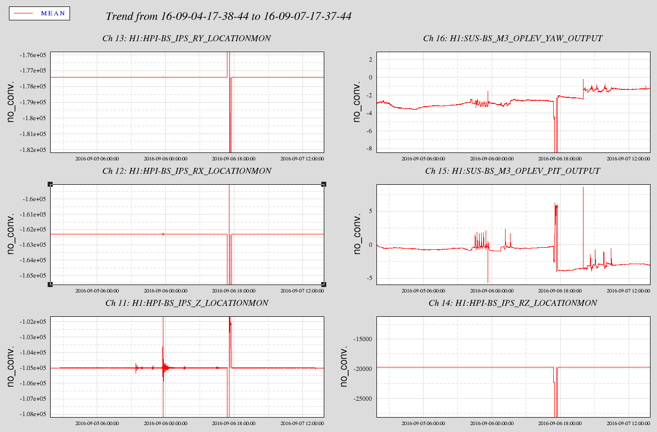
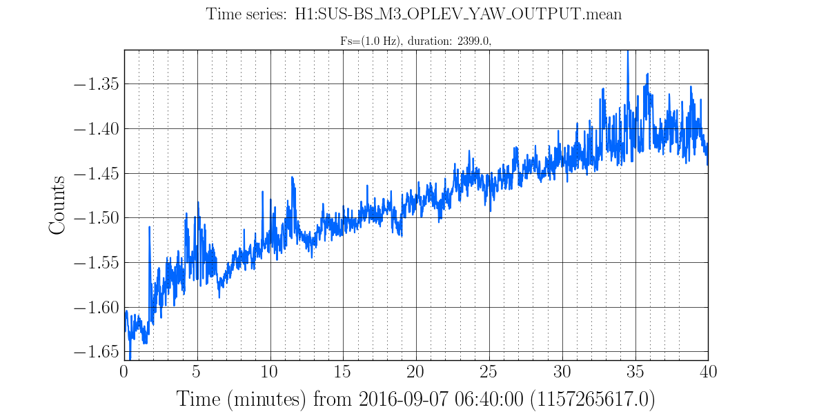
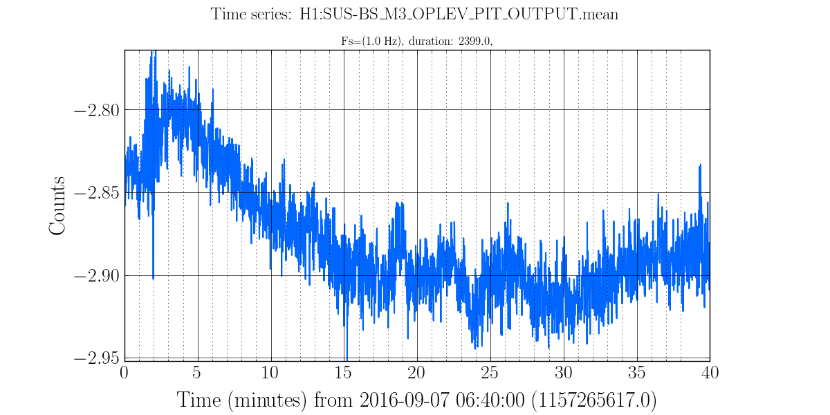
RobertS suggested a look at the BS OpLevs for position drifting. I would say there isn't a lot of drifting looking at three days--First Attachment.
But--HEPI moved BS Optic pitch 3 or 4 urads based on Optical Lever
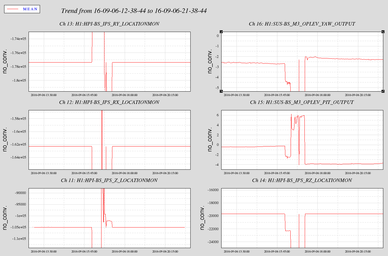
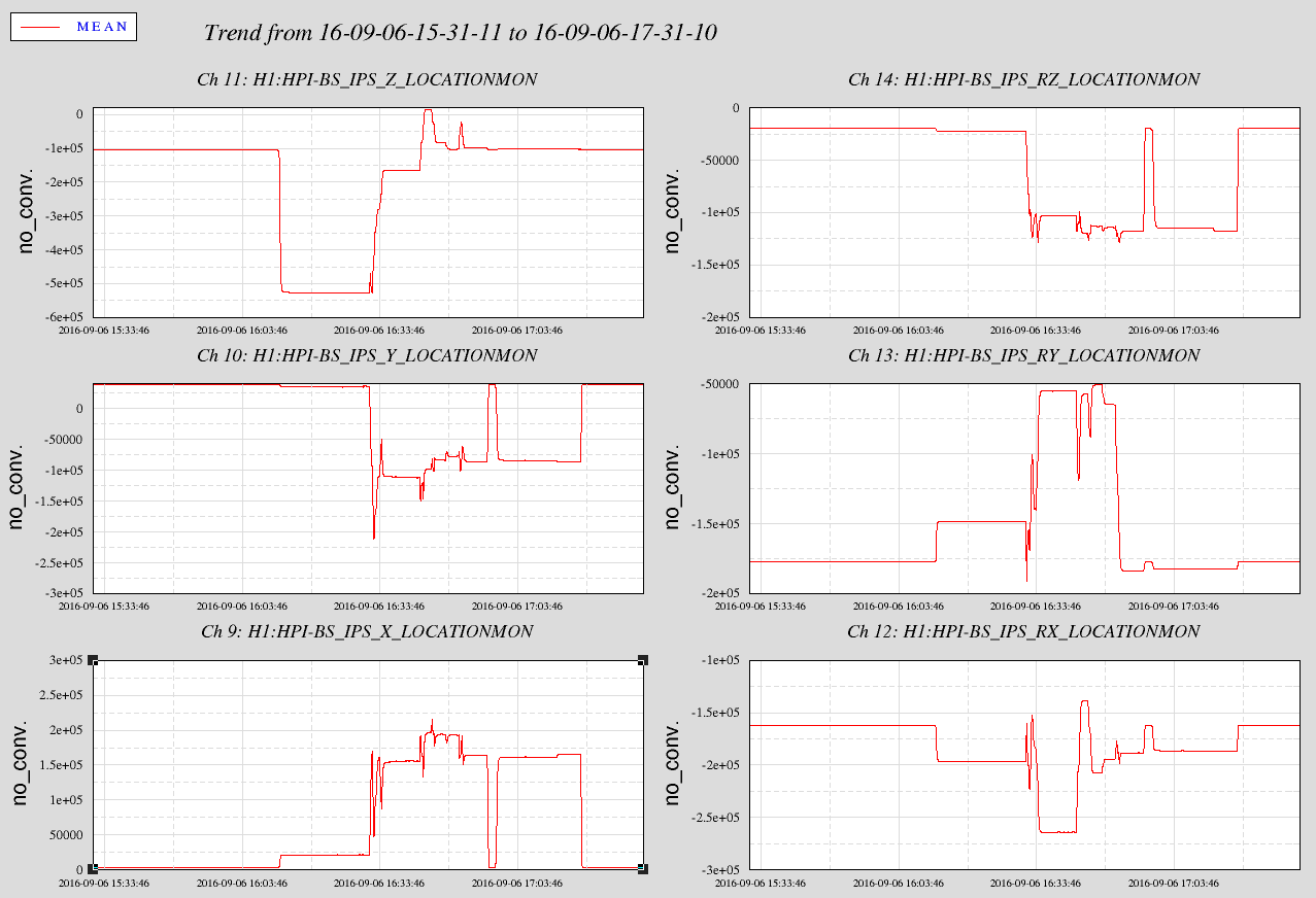
The first attachment is a 3 days showing the BS HEPI work done yesterday 29495 based on the HEPI Catesian location monitors. You can see that the HEPI Cartesian positionas are exactly the same as before the work but the YAW and moreso the Pitch are shifted immediately following the work on HEPI. The second attachment zooms into 9 hours and OpLev change is pretty much immediate with the reisolation of the SEI. I did a quick scan of a few months of this and see most of the time, the OpLev Pitch and Yaw don't change drastically after a de/re-isolation of HEPI. So I think the amount of change seen here yesterday is not the norm.
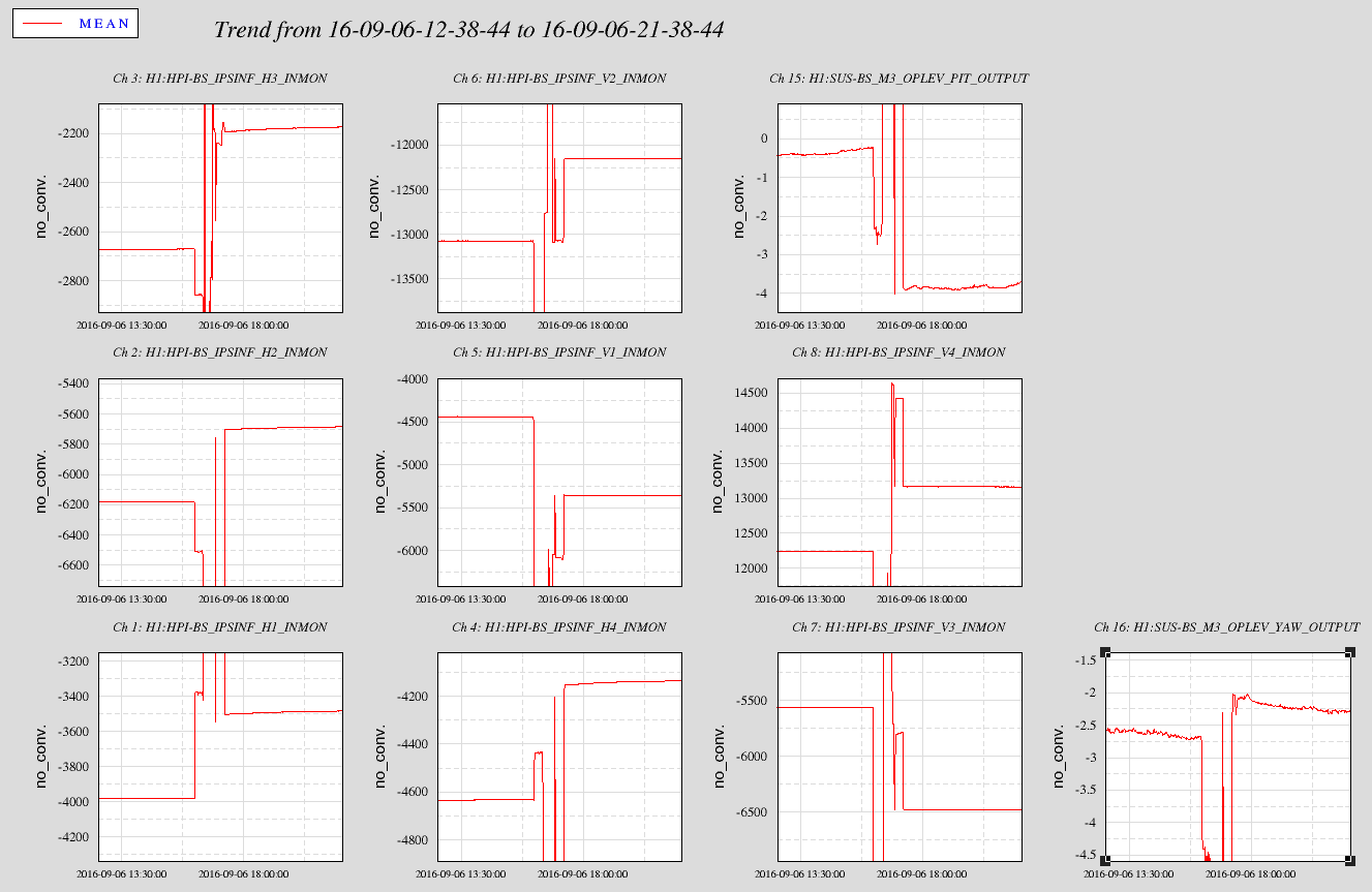
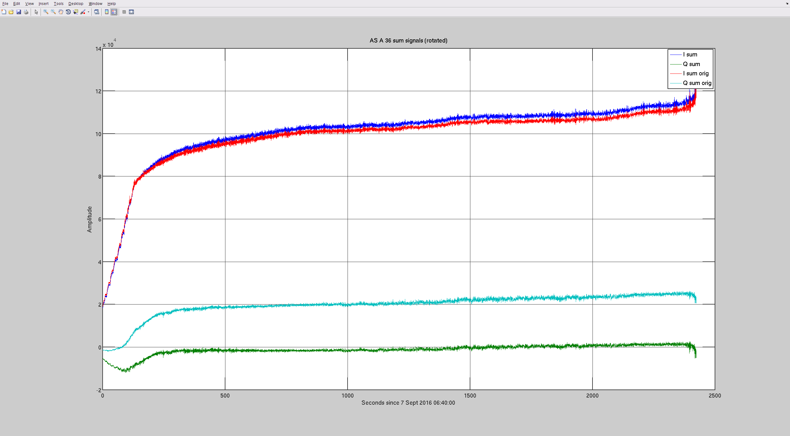
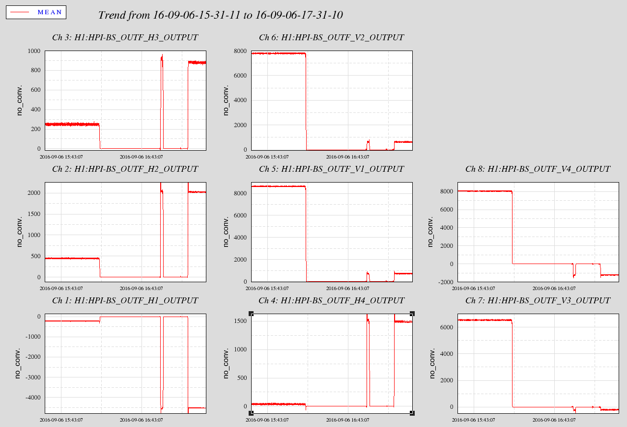
On the third attachment we see the actual change with the local Sesnors. For the four Horizontal sensors you can see that all shift about positive 4 - 500 counts. These actuators face opposite directions so these shifts essentially cancel and no YAW or Translation should occur. For the verticals, with different Actuator positions, it is hard to imagine not actually shifting the tilt of the table even with the same resolved cartesian position. Certainly the platform strain (in the actuator psoitions) as quantified by the Pringles is different. This is what we have though with AC couple pringle loops. I recommend we study the isolation sequence and maybe we can achieve better repeatability.
It is hard to imagine how this can affect the Optic Pitch but...