[Jenne, Terra]
We've been pretty frustratingly plagued by the CSOFT / dPdTheta instability today. Earlier today with Sheila, we were able to use the offsets from yesterday, but then later in the evening those offsets make things unstable when we go up in power. I'm starting to wonder if an initial alignment needs to be done, since the green arm powers (measured at LockingArmsGreen, or anything early in the sequence) have been decreasing with each lock. Maybe that will help?
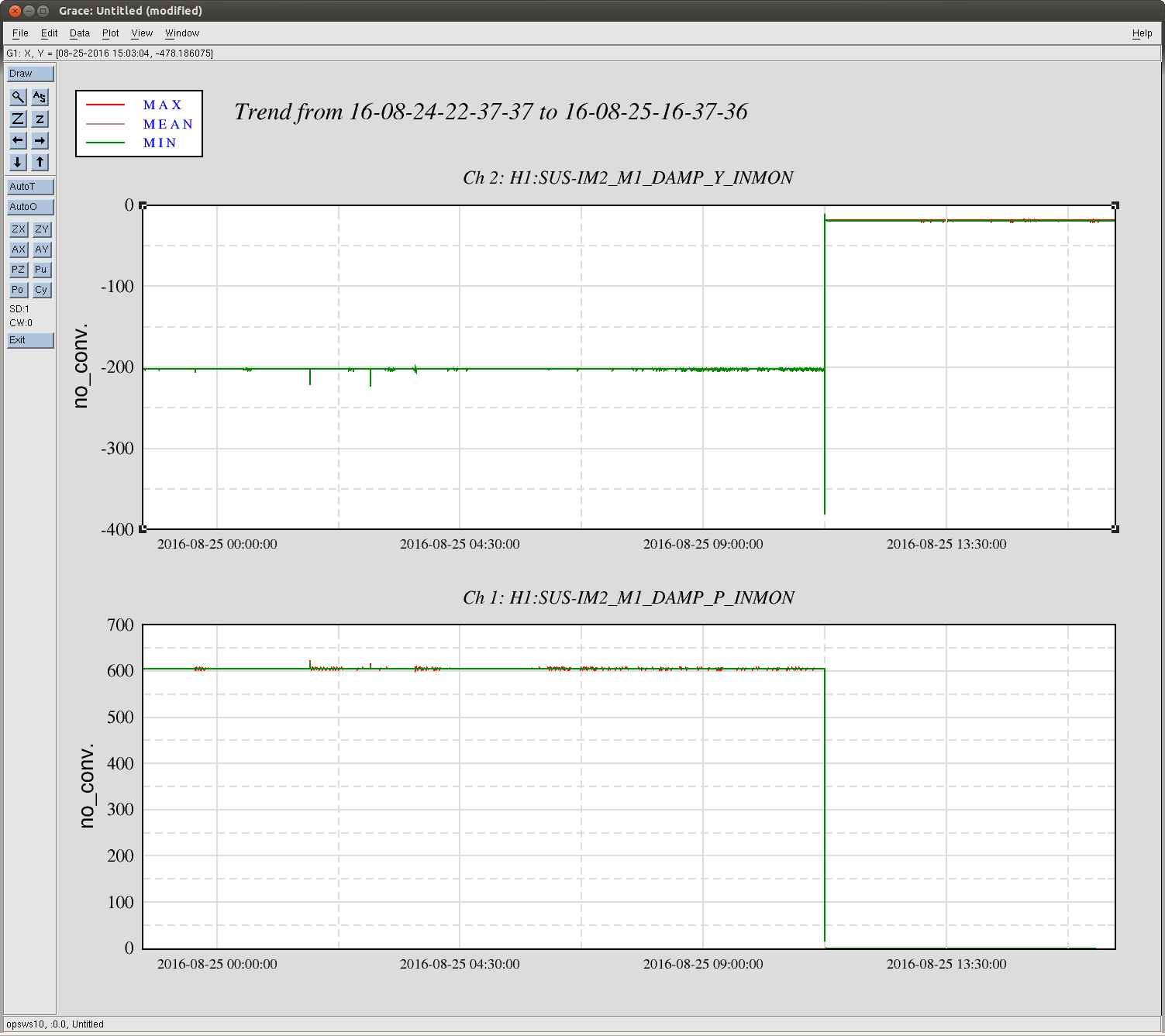
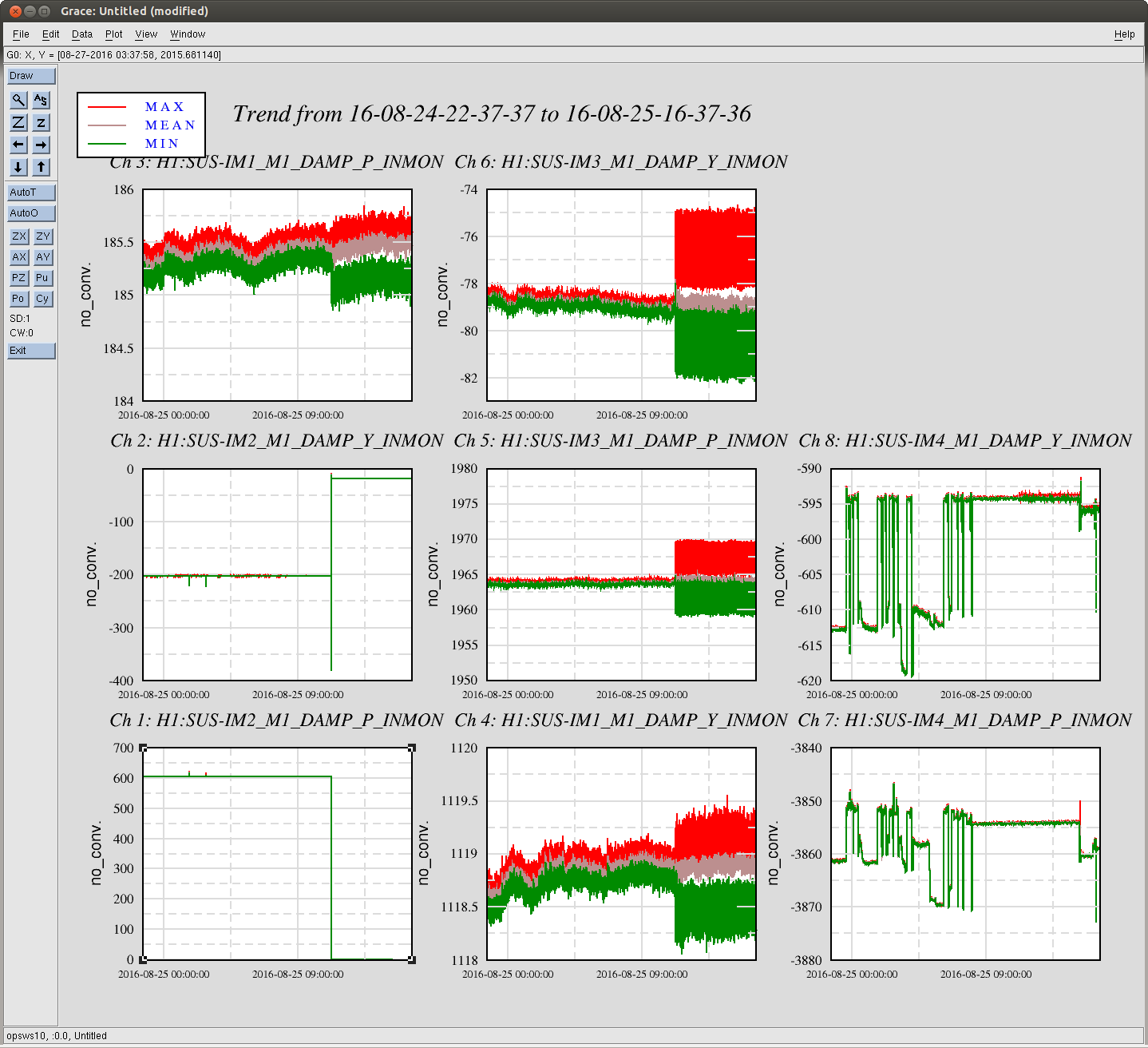
Sheila migrated the Soft offsets into the trans QPDs, so the IFO now aligns to that placewhen the soft loops come on. Also, the POPA offsets are engaged during ASC_Part2, so the IFO is aligned to yesterday's place. However, with this alignment at 2W, we cannot engage the roll mode damping. The last few hours we've been skipping over EngageRollModeDamping, and I've commented out the final roll mode gain setting that used to happen in DC readout. We don't seem to usually have much of a problem just leaving the damping off, but we can turn it on once we're at at least a semi-high power (maybe 20+ W?).
Since we kept being troubled by the CSOFT instability, we went back to trying new offsets. We think there's a little more that could be done, but we have a place where the recycling gain stays fairly constant as we power up. The recycling gain looks terrible at 2W (30ish), but then only decays to 28ish. This is in comparison with the usual decay to 22ish. Also with this alignment, when we're at high power, the green arm transmissions are both high. This seems like something that we want, since we think that the green and red beams are pretty well co-aligned after the Soft loops come on, so hopefully this means that we're closer to finding a place that maintains the alignment of the IFO from 2W to 50W.
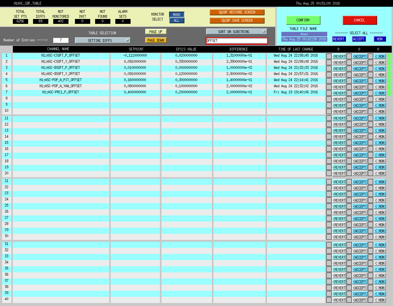
In the SDF screenshot, the POP_A offsets in the setpoint are what Sheila and Terra found last night, while the current values are the place that we like best so far tonight. The setpoint offsets for the soft loops aren't meaningful, but the current values are the ones that we like from tonight, which are on top of last night's offsets (which have already been put into the QPDs and accepted in SDF).
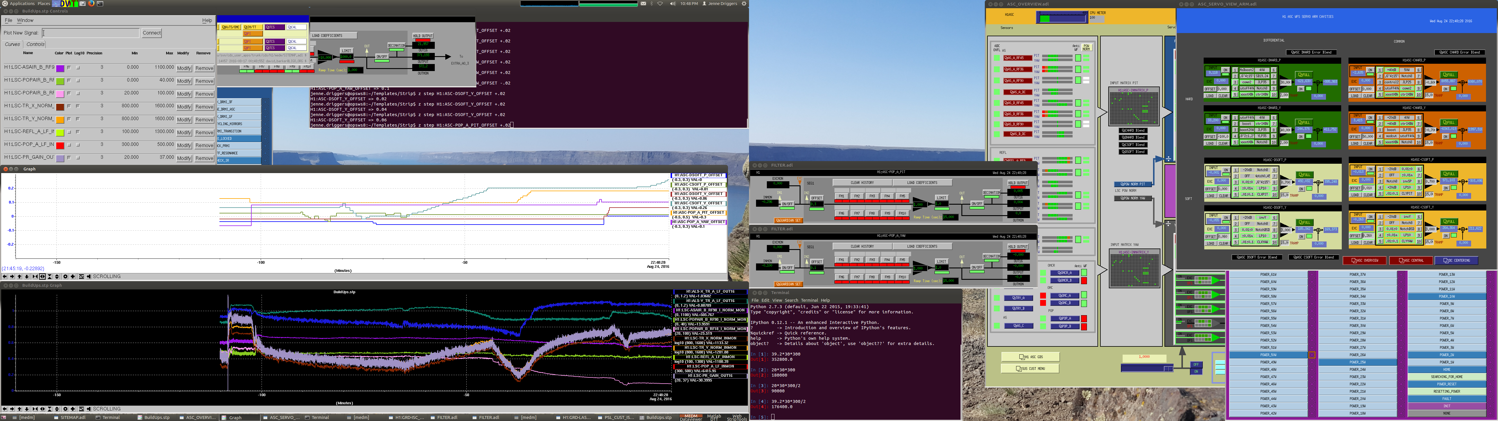
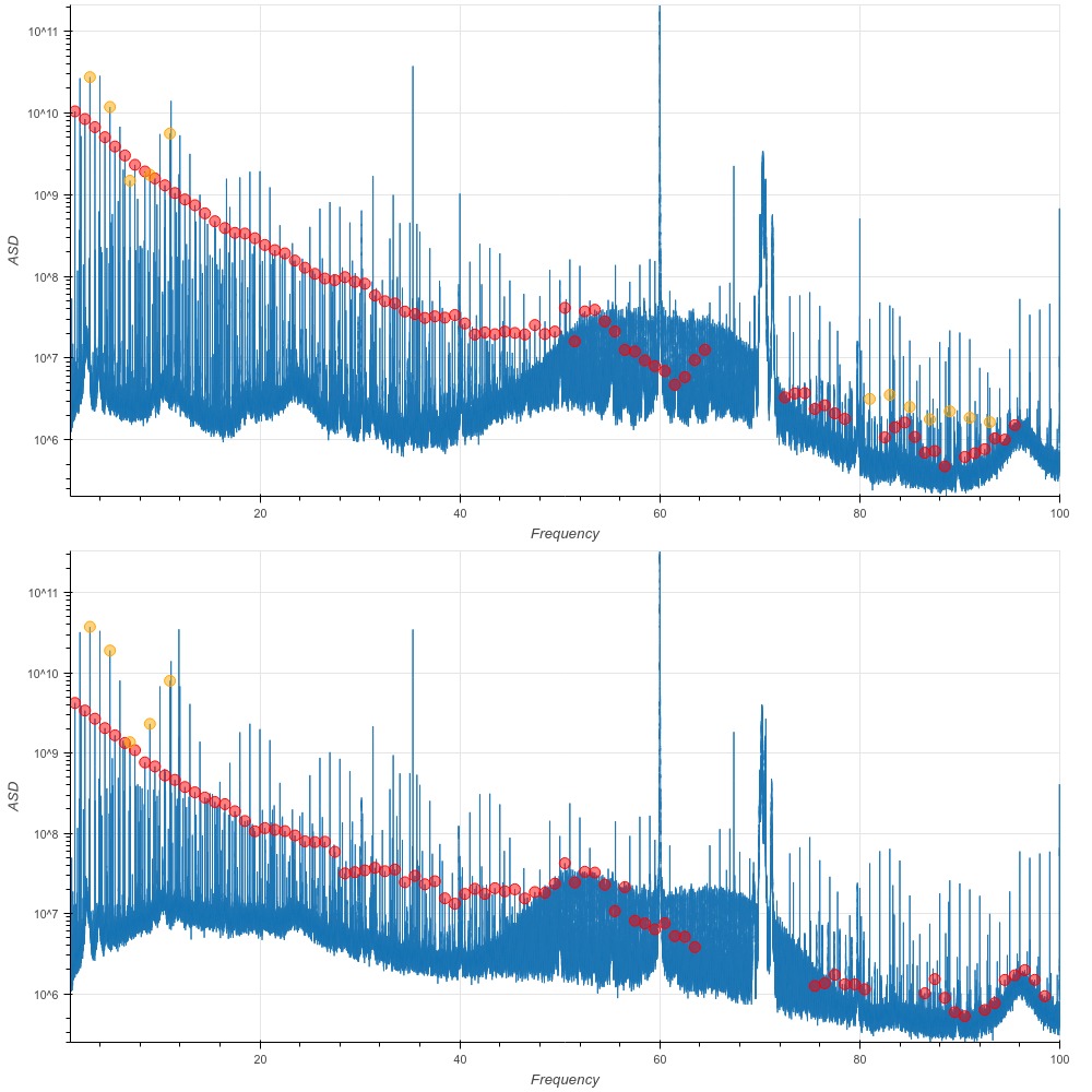
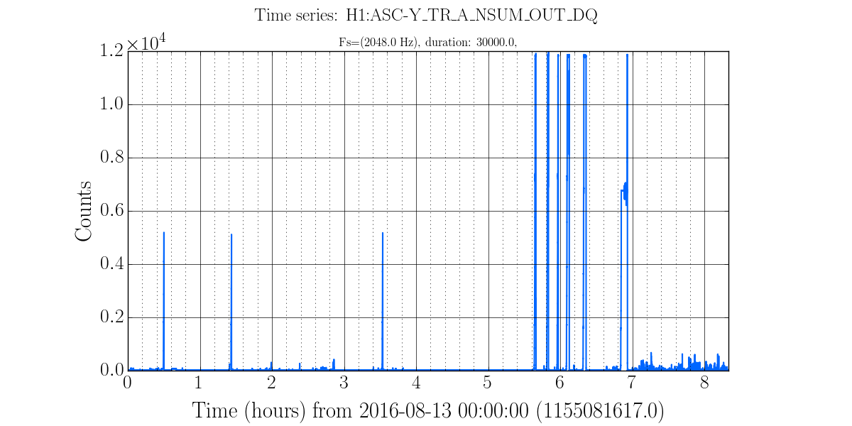
Attached also is a screenshot showing two striptools (and a bunch of other stuff that's basically ignorable). Right around -100 minutes is the inital power-up and corresponding power recycling gain drop. You can see that as we move offsets around, we're obviously changing the red and green arm powers, as well as the recycling gain. Note though the time around -15 min where both green arm transmissions (blue and teal) are high, and the PRC gain is high. Xarm green seems most strongly affected by Pop_A_pit, while Yarm green seems most strongly affected by DSOFT.
To help maintain these locks, we were increasing the ISS 3rd loop gain from -1 to -10. Also, we increased the SOFT Yaw gains from 3 to 7, and the Soft Pit gains from 0.5 to 0.7. This seemed to ameliorate most instabilities, although we still are sometimes struggling to hold the lock - I think it's perhaps an indicator of needing an initial alignment.