|
|
Name |
WP Date |
Description |
alogs |
|
1 |
6026 |
2016-07-28 |
Activity: Shutdown h1conlog1-master and h1conlog1-replica. Give the disks to LDAS to archive. |
https://alog.ligo-wa.caltech.edu/aLOG/index.php?callRep=28707 |
|
2 |
6027 |
2016-07-28 |
Activity: Start and run chilled water booster pump and Kobelco |
https://alog.ligo-wa.caltech.edu/aLOG/index.php?callRep=28713 |
|
3 |
6028 |
2016-07-28 |
Activity: Run signal cable for new Inficon BPG402 vacuum gauge to be installed on HAM6. Cabling will be routed from HAM6 to rack SUS-R5 (BSC3). |
|
|
4 |
6029 |
2016-07-28 |
Activity: Position 3 cleanrooms at the North & South doors of HAM6 for vent. |
https://alog.ligo-wa.caltech.edu/aLOG/index.php?callRep=28743 |
|
5 |
6030 |
2016-07-28 |
Activity: MONDAY -verify purge air dew point (testing Kobelco 7/28) -soft close GV 5 & 7 -vent HAM6 up to air -pull north and south doors (in chamber work Tues, Wed) WEDNESDAY -replace CC/pirani gauge with full range ion gauge on an all-metal valve THURSDAY -install doors -pump down HAM6 (~ 3 hrs until turbo can be turned on) FRIDAY -open GV 5 & 7 NOTE: most likely the week of Aug. 14th is when we can transition from turbo to IP only. This work will require crane and fork lift use. |
https://alog.ligo-wa.caltech.edu/aLOG/index.php?callRep=28821 |
|
6 |
6031 |
2016-07-28 |
Activity: Lock HEPI at HAM6 for duration of Vent unless intermittent unlocking is desired by commissioners/troubleshooters |
|
|
7 |
6032 |
2016-07-29 |
Activity: Tweak/calibrate servos, ISS especially. Check out the TTFSS field box functionality (or lack thereof). |
|
|
8 |
6033 |
2016-07-29 |
Activity: Collect video footage for LIGO article. Will have tour group and video activities on Saturday. Vern Sandberg and Rich Abbott to supervise activity for safety and compliance |
|
|
9 |
6034 |
2016-08-01 |
Activity: Connect output of Inficon guage (BSC7) to a safety interlock in the CER Mezzanine. Interlock enables/disables the high voltage power supplies to the ITM ESD. Will coordinate with vacuum team when connecting/disconnecting to vacuum gauge. A safety interface relay chassis D1400047 will be installed on top of rack in CER. |
|
|
10 |
6035 |
2016-08-01 |
Activity: investigate why epics values changed during the last two timing code upgrades. All EY computer systems will be restarted. No DAQ restart required. |
|
|
11 |
6036 |
2016-08-01 |
Activity: DetChar tour of LVEA |
|
|
12 |
6037 |
2016-08-01 |
Activity: In prep for ISS upgrades, install a binary IO card in h1psl0's IO Chassis and move one ADC card to make room. |
|
|
13 |
6038 |
2016-08-01 |
Activity: Move ISCT6 Take pictures of all cables connected to ISCT6 and document. Disconnect all cables from ISCT6. Insert lexan window to the viewports, remove bellows. Land ISCT6 and move it out of the way so we can remove the HAM6 door the first thing in the morning. Put yellow viewport protectors on HAM6 viewports. |
|
|
14 |
6039 |
2016-08-01 |
Activity: We would like to make a measurement while leaving CO2 on at high power overnight. There will be a script to turn the laser on/off automatically. |
|
|
15 |
6040 |
2016-08-01 |
Activity: Remove excess property from LVEA per Property Services. |
|
|
16 |
6041 |
2016-08-02 |
Activity: Routine (semi-annual) maintenance - measure powers, tweak alignments, calibrate, etc. Area of Activity: Yend Pca |
|
|
17 |
6042 |
2016-08-02 |
Activity: Installation and commissioning of the instrument in the bier garten, power and data cable pulling, Area of Activity: LVEA Newtonian Noise Array -- Compact BRS Addition |
https://alog.ligo-wa.caltech.edu/aLOG/index.php?callRep=28829 |
|
18 |
6043 |
2016-08-02 |
Activity: Swap out CO2Y RF driver. Area of Activity: TCS |
|
|
19 |
6044 |
2016-08-02 |
Activity: Conducting a brief tour of two in LVEA. This is a potential applicant for the LLO operator position, who has contacted me via a public tour. Undergrad in Physics, specializing in optics and lasers. |
|
|
20 |
6045 |
2016-08-02 |
Activity: Conduct a tour of visitors from the Bejing Normal University, China. |
|
|
21 |
6046 |
2016-08-02 |
Activity: Tour for candidate. |
|
|
22 |
6047 |
2016-08-02 |
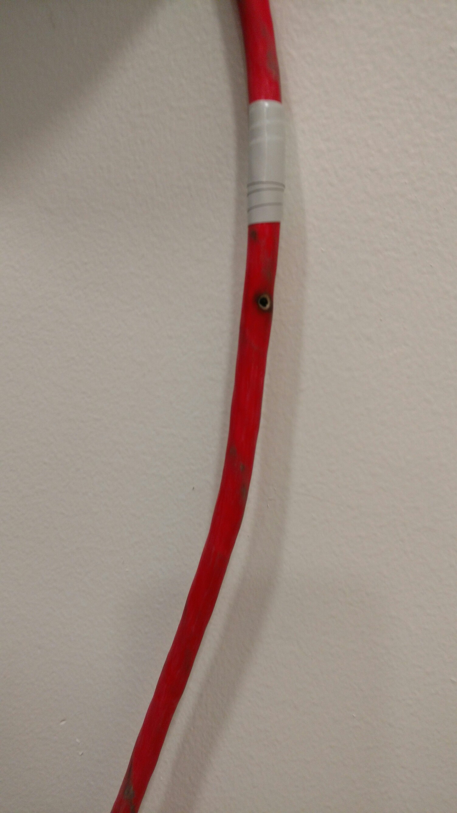
Activity: Unplug and test HV cable for ion pump at the Y-End station, and remove and replace broken component(s). Area of Activity: Vacuum, Y2-8 Ion Pump Cable at Y-End and at Y2-8. |
https://alog.ligo-wa.caltech.edu/aLOG/index.php?callRep=28847 |
|
23 |
6048 |
2016-08-02 |
Activity: Survey all viewport covers to confirm the lexan assemblies have all hardware in tact. |
|
|
24 |
6049 |
2016-08-02 |
Activity: Survey all viewport covers to confirm the lexan assemblies have all hardware in tact. |
|
|
25 |
6050 |
2016-08-03 |
Activity: Candidate tours of LVEA, Wed am, Wed pm, Thu pm |
|
|
26 |
6051 |
2016-08-03 |
Activity: Convert QUAD PUM/L2 output matrix to ramp matrix for independent channel switching of coil driver analog filtering. Approved ECR is E1500045. |
|
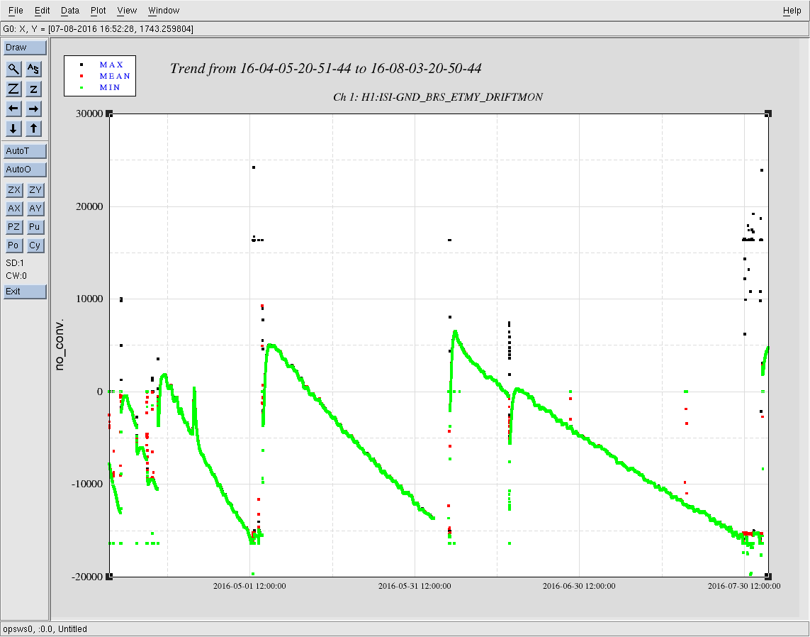

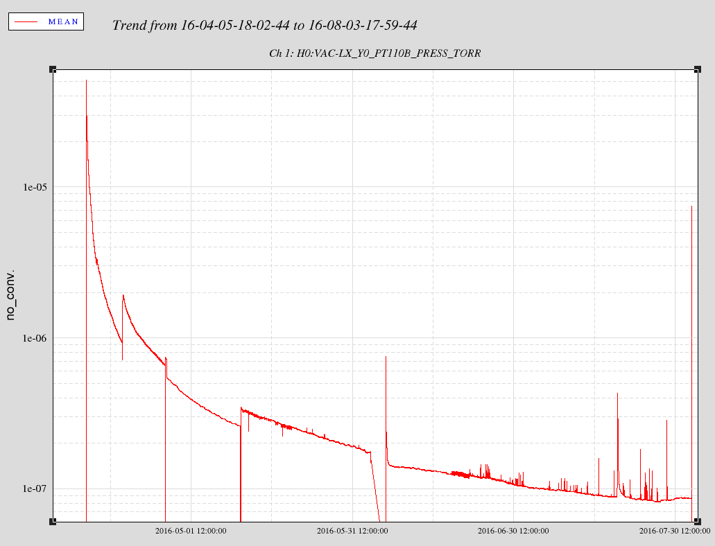
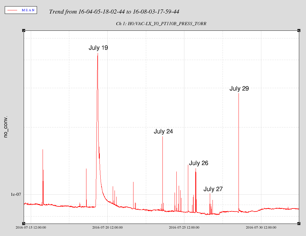
Connected cable to controller and turned ion pump on. Pump is pumping now, see attached for 3 hour trend data.
Work done under WP #6047 and FRS ticket 5992 closed