Evan G., Jeff K., Evan H.
Summary:
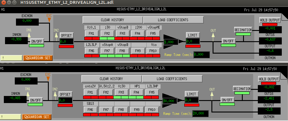
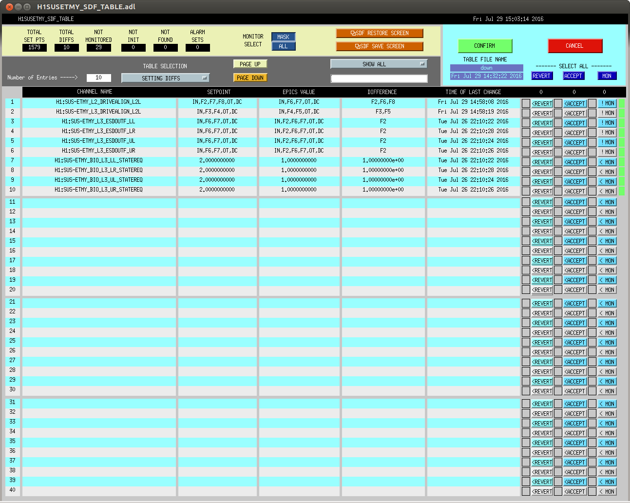
We have updated the L2-L3 crossover filters to reduce the effect of the L2 actuation on the superactuator at frequencies above the L2-L3 crossover. In addition we have turned off the vStopB filter in the L2 drivealign bank. The old filters remain in the filter bank, but are turned off in case we need to revert. The SDF has been updated to reflect these changes.
Details:
The old lowpass [ :30], and highpass [0:30] filters were allowing too much interaction of the L2 stage on the frequencies above the crossover. We needed more aggresive rolloff of the L2 stage. A new design was used to develop prototype lowpass and highpass filters that were then normalized to produce complementary filters. The trick was to add some additional filtering in addition to the single pole or single-zero/pole design.
The Matlab zpk prototype lowpass is:
    29.804 (s^2 + 792s + 4.077e06)

	  ----------------------------------

	  (s+94.25) (s^2 + 1192s + 1.304e06)
and the prototype highpass is:
  0.68377 s (s+0.4816) (s+40.81)

	  -------------------------------

	  (s+125.7) (s^2 + 35.75s + 1174)
The resulting complementary filters are the lowpass:
      43.587 (s+125.7) (s^2 + 35.75s + 1174) (s^2 + 792s + 4.077e06)

	  ----------------------------------------------------------------------

	  (s^2 + 27.96s + 1124) (s^2 + 256s + 1.986e04) (s^2 + 1087s + 1.175e06)
and the complementary highpass:
        s (s+94.25) (s+40.81) (s+0.4816) (s^2 + 1192s + 1.304e06)

	  ----------------------------------------------------------------------

	  (s^2 + 27.96s + 1124) (s^2 + 256s + 1.986e04) (s^2 + 1087s + 1.175e06)
Putting this into Foton yields the lowpass design:
zpk([63.027+i*315.14;63.027-i*315.14;2.8446+i*4.6522;2.8446-i*4.6522;20], [20.375+i*9.3751;20.375-i*9.3751;2.2252+i*4.8498;2.2252-i*4.8498;86.475+i*149.24; 86.475-i*149.24],1,"n")
and the highpass design (properly normalized to 1 at high frequency):
zpk([94.821+i*155.07;94.821-i*155.07;0;0.076645;6.4948;15], [20.375+i*9.3751;20.375-i*9.3751;2.2252+i*4.8498;2.2252-i*4.8498;86.475+i*149.24; 86.475-i*149.24],1,"n")gain(0.000578996)
These are installed in the L2 and L3 drivealign banks as L2L3LP and L2L3HP, respectively.
We have compared the old and new design and the effect on the DARM actuation and DARM open loop gain and closed loop suppression, and we are satisfied with the improved filter design. Attached is a series of figures to illustrate the new design (see the plots.pdf file)
Figure 1: actuation plant transfer function (left plots) and the PUM/TST ratio (right plots)
Figure 2: current state of the distribution filters (before any modification)
Figure 3: current state of the actuation authority (before any modification) -- note the black curve has ripples in the 100-900 Hz band
Figure 4: new crossover filter design -- prototype and final design
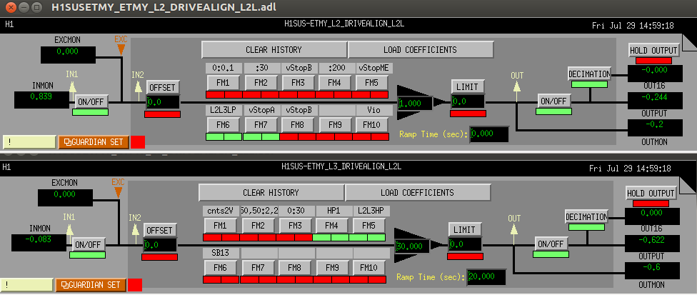
Figure 5: new distribution filter design from Matlab continuous filters -- note that we turn off the vStopB filter module in the L2 drivealign bank
Figure 6: new actuation authority from the Matlab filters -- note the improvement in the black curve with much less ripple than before
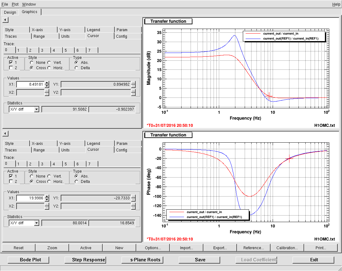
Figure 7: using new design, L2 and L3 actuation transfer functions: drive at input to L3 lock bank and look at L3 response for both L2 and L3 paths and taking the sum
Figure 8: using new design, the ratio of the two single curves in figure 7 -- note the transfer function is unity at 23.3 Hz and with a phase margin of 67 degrees
Figure 9: new distribution filter design as implemented in Foton -- note that these are the same as the Matlab design
Figure 10: new actuation authority from the Foton filters -- again, same as before
Figure 11: compare the DARM open loop gain and closed loop suppression from the current state (old) and using the new filter design and also when there is no SRC detuning -- note there was a lingering 400 Hz notch filter in the ER9 run that shouldn't have been there (Evan H to make sure this is off) and this model takes into account the increase of the digital DARM gain to 1400. The blue curves have little ripple above 100 Hz, and the phase margin is actually a little larger than before, about 48 degrees. The gain peaking is roughly the same as before ~4 dB.
Figure 12: A final acutation authority plot showing the new total is much improved over the old total, especially in the range of 100-900 Hz (see zoom on right hand plots).
For the record, also attached are screen shots of the L2/L3 drivealign filter banks before and after the changes as well as a screenshot of the SDF.